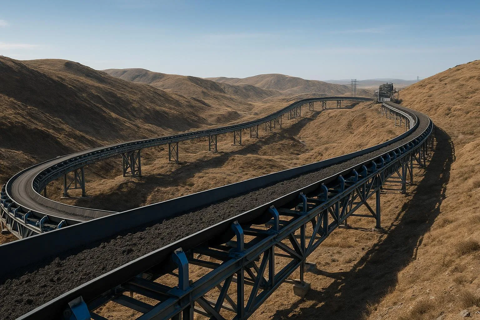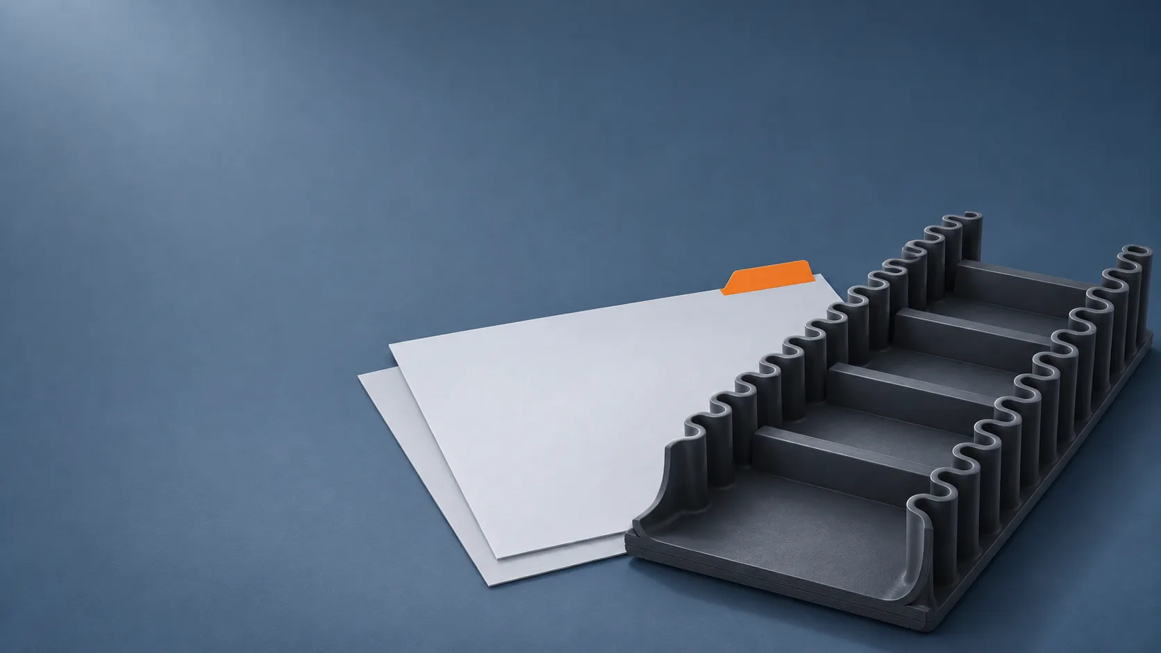
A sidewall conveyor belt specification needs to describe the base belt, corrugated sidewalls, transverse cleats and the conveyor interfaces as one assembly. Overall belt width and sidewall height are useful starting points, but they leave carrying space, cleat layout, bending limits and delivery length unresolved. Use a common drawing revision, ask suppliers to identify deviations, and keep a preliminary quotation separate from an approved construction.
This guide helps industrial bulk-material buyers prepare that information for a new assembly or a replacement. The sidewall belt product scope provides a destination for the inquiry; a particular construction, material grade and supply arrangement still need confirmation. The workflow below prepares an RFQ, not a capacity calculation, manufacturing procedure or installation instruction.
1. Start the sidewall conveyor belt specification with duty and route
Collect the material record and conveyor layout before choosing attachments from a catalogue. The assembly must fit both the material pockets and the route that those pockets travel. A taller sidewall does not, by itself, establish that a system can move the required tonnage or negotiate its bends.
Public product descriptions, such as Metso’s sidewall conveyor belt overview, identify a cross-rigid base belt, corrugated sidewalls and cleats as interacting components. For an RFQ, turn that description into a duty record that the proposed assembly can be assessed against.
| Input | What to record | Why an abbreviated value is insufficient |
|---|---|---|
| Material | Identity, bulk density, size distribution and maximum lumps | A material name alone does not define pocket loading |
| Flow | Required normal and peak mass flow, with units and duration | A peak requirement should not be mistaken for continuous duty |
| Condition | Moisture, stickiness, abrasion, oils or other relevant exposure | The cover, sidewalls and cleats all need an appropriate proposal |
| Temperature | Material and ambient conditions, including peaks and contact duration | A general “heat resistant” label does not resolve the duty |
| Conveyor | Speed, incline, lift, horizontal sections and loading/discharge arrangement | One inclination angle does not describe the complete route |
Provide a route drawing showing carrying and return runs, transitions, direction changes and take-up arrangement. For a replacement, identify the conveyor and existing assembly reference, and record any difference between the current layout and the original drawing. Keep material observations, drawings and operator reports distinguishable from confirmed design inputs.
If the belt family itself remains undecided, check the material and incline constraints first. A sidewall belt is a system option to evaluate against the duty, rather than an automatic solution for every steep incline.
Mark missing information explicitly. An offer based on assumed density, speed or lump size should list those assumptions so the technical owner can resolve them before approval.
2. Describe the base belt independently of the attachments
Give the base belt its own specification block. Include overall width, carcass type, nominal full-belt tensile rating and units, construction reference, top and bottom covers, overall thickness and the proposed compound. Where values are not yet selected, request a documented proposal rather than inserting an unverified catalogue value.
Longitudinal strength and transverse stiffness answer different questions. The carcass must address the belt’s tensile duty, while the required lateral support and stability need their own construction assessment. Two belts with the same nominal tensile rating need not behave the same way across their width.
For example, Fenner Dunlop’s Rigitra description identifies cross-stabilized construction for the transverse rigidity needed with sidewalls or cleats. That is a product-specific example of why the base belt needs attention. It does not establish that another belt with a similar strength marking has the same reinforcement or compatibility.
Ask the supplier to explain the proposed cross-rigid base belt construction and its suitability for the documented supports and route. Do not assume that adding walls and cleats to an ordinary flat belt produces an equivalent assembly.
Keep strength notation unambiguous. A nominal full-belt rating is different from a single-ply fabric designation, and neither is a purchase-approved operating tension. The project’s responsible designer must confirm the tension and joint criteria for the selected construction; procurement should not substitute a universal safety factor.
Finally, distinguish the base width from the space available to carry material and from the clear edges needed for support or guidance. An overall width can be correct while the attachment positions leave insufficient room for the existing return arrangement. That relationship belongs on the assembly drawing.
3. Put sidewall and cleat dimensions on one drawing
Use an assembly drawing with a plan view, a transverse section and the profile details needed to interpret the attachments. State the units and height datums. A dimension measured from the top cover should not be silently compared with one measured from the underside of the base belt.
Identify the sidewall type and profile reference, height, foot or attachment width, reinforcement where proposed, and position relative to each belt edge. Corrugation geometry also needs a defined reference. A straight line drawn between two walls cannot describe every local opening along a corrugated profile.
For the transverse cleats, record profile type, height, length across the belt, orientation and longitudinal pitch. Show how their ends meet or approach the walls, including any proposed fastening or sealing details. The supplier should define the required construction; the RFQ should not invent a corner arrangement from a photograph.
| Dimension | Direction and reference to define | Question for the supplier |
|---|---|---|
| Overall base width | Across the belt, edge to edge | Does the quoted width refer to the base belt? |
| Clear carrying span | Between identified internal wall surfaces | Where is the span measured within the corrugation? |
| Sidewall and cleat heights | From the stated assembly datum | Are both values referenced to the same surface? |
| Cleat pitch | Along belt travel, for example between corresponding cleat centre lines | Is the value a repeat pitch or the clear gap between faces? |
| Cleat end clearance | Across the belt, from the cleat end to the identified wall surface | Is this a nominal, minimum or locally varying gap? |
| Corrugation pitch | Along the sidewall between repeating profile features | Which profile features define the repeat? |
The phrase sidewall belt cleat spacing can refer to different dimensions in different documents. Write “longitudinal cleat pitch” and “transverse cleat end clearance” as separate fields, with their reference surfaces shown. Do not treat a component code or the word “spacing” as a substitute for the drawing.
Likewise, define “effective width.” It might be used for a clear internal span or a supplier’s calculation parameter. Obtain its meaning before using it to compare capacity proposals. Pocket volume and usable filling depend on more than a rectangular width-times-height envelope, so this drawing exercise is not a capacity approval.
The output of this step is a shared geometry record. It should let the buyer point to a dimension and let every supplier understand the same location, direction and datum.
4. Check the complete assembly against bends and return supports
Send the attachment drawing and route drawing together for compatibility review. Provide the pulley schedule, pulley functions and diameters, operating tension information, bend directions, transition geometry and carrying and return support details. Identify which parts are existing constraints and which may be redesigned.
A base-belt minimum pulley diameter is only one part of the review. The walls and cleats must also pass through the specified bending conditions, and the complete assembly must have the necessary clearances. A profile that fits on a straight drawing may behave differently around a pulley or a reverse bend.
Siban’s sidewall guidance explicitly identifies sidewall, cleat, base-belt and tension criteria when assessing the controlling drum diameter, and calls for project-specific assessment. Its published reference rules belong to its products and conditions; they should not become a universal multiplier for another assembly.
Use the construction-specific pulley selection guide to organize the information for that review. Ask the actual assembly supplier to confirm limits for the offered components, compound and joint arrangement against each relevant position.
Check return supports and available edge zones, guide arrangements, adjacent structure and any contact with the attachments. Also review loading and discharge interfaces, cleaning access and the proposed means of accommodating the profiled belt. Keep these as supplier and project-engineering questions, rather than prescribing support spacing or field alterations in the RFQ.
A change in wall height, foot width, cleat shape or attachment position may affect several interfaces at once. Require the response to identify those effects. Approval of one component’s catalogue size does not close the complete assembly review.
5. Declare length, splice and delivery scope
State what length is being purchased and how it is defined. A finished endless circumference, an open supply length and a length that includes a joint preparation allowance are different order descriptions. The supplier should state the proposed measurement basis and applicable tolerances for the delivery form.
| Scope item | Declaration needed before comparison | Responsibility to identify |
|---|---|---|
| Belt length | Open sections or finished endless loop; measurement basis | Who confirms the required installed geometry? |
| Joint | Proposed joint type, allowance and construction-specific documentation | Who designs, executes and accepts it? |
| Attachment layout at the joint | Interruption, termination and reinstatement arrangement, if applicable | Who supplies and completes each part? |
| Packing | Proposed support, protection, package dimensions and handling conditions | Who checks transport and site-receiving constraints? |
| Documentation | Drawing revision, material identification and agreed inspection records | Who issues the records and links them to the supplied assembly? |
Ask for a plan for the joint region that addresses the base belt and the attachments. Do not infer from “splice included” that sidewall and cleat work, joint materials, field labor and commissioning are all priced. No bonding or splicing method should be selected from this article; the procedure belongs to the chosen construction and qualified personnel.
When you agree the delivery lengths and packing, request a proposal specifically suited to the assembled sidewalls and cleats. A plain-belt rolling arrangement is not automatically appropriate for a profiled assembly. Confirm package handling and storage requirements with the supplier and receiving site.
Also agree the evidence needed at order and delivery stages. Component references, an approved assembly drawing and the agreed inspection plan serve different purposes from a company certificate. Where adhesion or other performance evidence is required, define the method, specimen, acceptance basis and relationship to the offered construction with the technical owner. This article sets no universal test threshold or certification requirement.
6. Issue one RFQ and retain the supplier’s deviations
Put the duty record, drawings and delivery requirements under one RFQ revision. Require a response against that revision, with proposed changes visible. A revised price without a revised technical response can leave an earlier assumption unnoticed.
Consider this hypothetical quotation comparison, not a customer case or a recommended construction. Two offers both list a 1,000 mm base width, 160 mm sidewalls and 250 mm cleat pitch. Those numbers still leave several decisions open:
| Review point | Offer A states | Offer B states | Required clarification |
|---|---|---|---|
| Cleat pitch | Corresponding cleat centre lines | “Spacing 250 mm” | Define B’s direction and reference surfaces |
| Internal opening | Dimensioned on an assembly section | Not shown | Obtain the clear-span definition and drawing |
| Conveyor interfaces | Listed pulley and return positions reviewed | “Suitable for steep conveying” | Obtain a position-specific compatibility response |
| Delivered length | Open sections with joint scope identified | “Complete belt” | Resolve length basis, joint work and exclusions |
There is no supplier recommendation in this table. Offer A is more explicit in those fields, but still needs the same technical and commercial approval as any proposal. Offer B may become comparable after clarification. Missing information is a reason to ask, not proof of a defective product.
A practical RFQ response request can read:
Identify the duty record and drawing revision used for your offer.
Confirm the proposed base-belt construction and cover specification.
Return the sidewall/cleat assembly drawing with dimension datums.
State longitudinal cleat pitch separately from transverse end clearance.
List pulley, bend, return-support and transfer-interface assumptions.
Declare open or endless length, joint allowance and attachment work.
Identify packing, documentation and delivery-scope inclusions.
For each requirement, mark conforms, deviates or pending clarification.
Give the proposed alternative and affected documents for each deviation.
Identify decisions needed before manufacture and the approving parties.
Keep the supplier’s technical deviation register with the final quotation. Distinguish permission to provide a budget price from drawing approval and manufacturing release. If an input changes, identify which component, interface or acceptance decision needs review again; approval should follow the revised documents.
BisonConvey operates as a trading company coordinating with multiple partner factories. To request an order-specific supply review, submit the drawing and duty record with the geometry, route, quantity and open questions. Available construction, technical compatibility, evidence, delivery terms and each party’s responsibilities require confirmation for that inquiry.