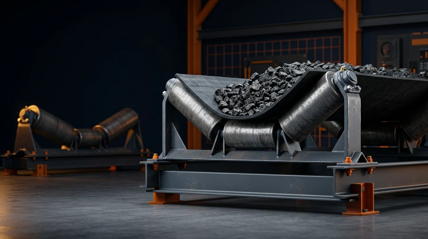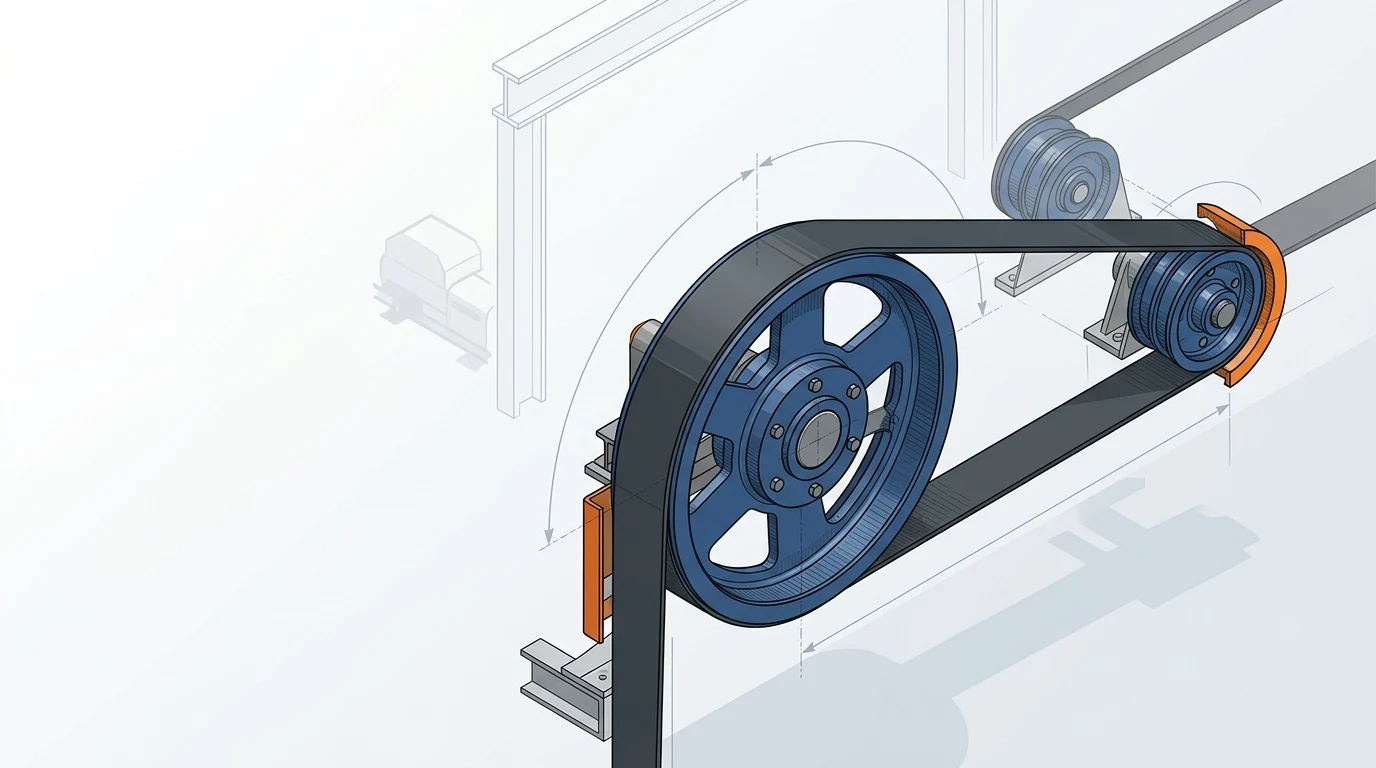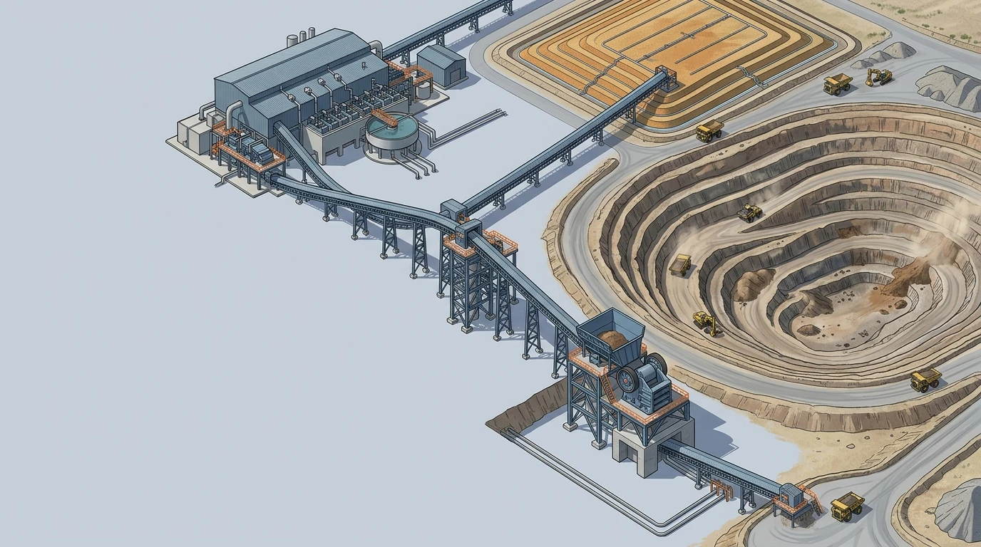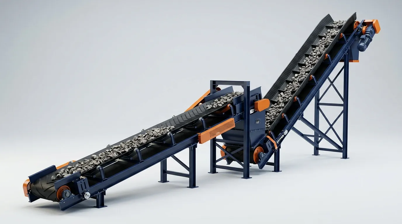
A belt conveyor has no universal maximum incline angle. For a conventional smooth belt, the usable angle is set by the conveyed material and operating conditions—not just the belt cover. Chevron or cleated belts add mechanical retention when a layout slightly exceeds the proven smooth-belt limit; corrugated sidewall belts create pockets for steep and even vertical conveying. Start with the material at its worst credible condition, calculate the layout angle, then validate the complete belt-and-loading system before you release an RFQ.
1. Treat angle as a material-and-system limit, not a belt catalogue number
The question “what is the maximum conveyor angle?” sounds as though one number should settle the specification. It cannot. The useful question is: at this angle, will this material remain stable on this moving belt through loading, acceleration, and discharge?
Material can roll, slide, tumble, segregate, or be carried backward at the return transition long before a nominal belt-type limit is reached. A dry, angular crushed product may sit more securely than rounded or lubricated particles. A material that is stable in a slow, evenly fed trial can behave differently after belt speed, feed trajectory, moisture, or tonnage changes.
The CEMA Belt Conveyors for Bulk Materials reference is a design resource for belt selection, capacity, and general applications; use the applicable tables and the project design basis rather than copying a generic angle from a blog post. CEMA's current Belt Book listing also makes clear that this is a detailed engineering reference, not a one-number rule.
For an early feasibility check, calculate the geometric angle, then compare it with material-specific data. The Incline Angle Calculator is useful for this first screen because it separates the layout calculation from the choice of smooth, profiled, or sidewall construction. It is not a substitute for testing or manufacturer approval.
Decision rule: if a quoted maximum angle does not state the material condition, belt surface, speed, and loading basis, treat it as a marketing reference—not a design limit.
2. Calculate the layout angle before deciding which belt type to compare
For a straight inclined conveyor, calculate the belt-path angle from the vertical lift and the inclined belt length:
α = arcsin(H / L)
Where H is vertical lift and L is the belt-path length. If you only have horizontal run R, use α = arctan(H / R) instead. Record which geometry was used; mixing belt length and horizontal run produces a misleading answer.
The calculation tells you the required angle. It does not tell you whether the material will stay put. That second question depends on the interface between product and belt, plus the disturbances introduced by the operating conveyor.
For example, a conveyor that must rise 8 m over a 20 m belt path has a geometric angle of about 23.6°. That result should not immediately become “specify a 24° chevron belt.” First establish the material's normal and worst-case conditions, determine the maximum smooth-belt angle for those conditions, and review the loading zone. If the material is damp in one season and free-flowing in another, the lower-retention case should govern unless the process prevents it.
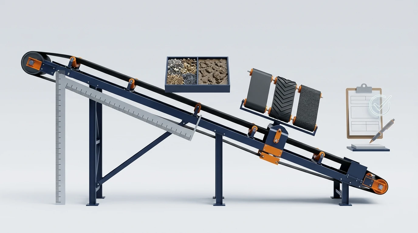
The distinction matters because static friction alone is optimistic. A running belt has feed impact, vibration, belt sag, starts and stops, and a changing material profile. In a published coal application, Continental distinguishes conventional troughed inclines usually at 20° or less from a closed-trough pipe conveyor used up to 30°; that project example is a reminder not to transfer a specialized-system result to a conventional belt.
3. Check the variables that can lower the workable angle
Use a material-and-duty sheet before you compare constructions. “Limestone,” “coal,” or “sand” alone is not enough because particles from the same material family can behave very differently.
| Input to confirm | Why it changes the incline decision | What to record |
|---|---|---|
| Particle size, shape and fines | Rounded material can roll; fines can either bind or behave like a lubricating layer. | Lump range, percentage fines, angular/rounded description |
| Moisture range | A small amount of moisture can change cohesion; free water can reduce traction or create build-up. | Normal, wet-weather and upset-condition moisture |
| Bulk density and feed rate | Affect the material bed, loading energy and the force needed to stabilize the stream. | Design and maximum throughput |
| Belt speed and start/stop profile | Faster loading, vibration and transient acceleration reduce the margin available at a steep angle. | Normal speed, starts per hour, VFD/ramp details |
| Loading geometry | A poorly directed stream may tumble downhill before it settles. | Chute direction, drop height, skirt length |
| Belt support and sag | Local sag changes the material profile and can destabilize a bed near its limit. | Carrying-idler pitch, trough angle, target sag |
| Cleaning and discharge | Cleats and pockets change how cleaners, plows, transfer points and discharge geometry work. | Cleaner arrangement, carryback limit, discharge requirement |
Do not use the angle of repose glossary definition as the conveyor limit. Repose describes a pile of material against itself. An inclined belt adds a moving cover surface, loading energy, and dynamic disturbances. It can help you understand material behavior, but it cannot approve a conveyor angle on its own.
At the same time, do not assume that changing from fabric to steel cord fixes slide-back. Carcass selection addresses tensile strength, elongation, distance and dynamic duty. Surface geometry and retention solve a different problem. Keep those decisions separate until the engineering inputs show they are linked.
4. Compare smooth, chevron and sidewall systems by the retention mechanism
The table below is a preliminary decision matrix, not a universal angle chart. It is designed to stop the two common mistakes: using a smooth belt because it is familiar, or jumping to a sidewall system before checking whether a modest layout change or profiled belt is enough.
| Construction | How it retains material | Best starting use case | Key limits to validate before selection |
|---|---|---|---|
| Smooth / plain-top belt | Relies mainly on material-to-cover friction and stable loading. | The required angle is below the material's verified smooth-belt limit and the line needs conventional cleaning and transfer hardware. | Material condition, local sag, speed, feed stability, and the margin to the verified limit. |
| Chevron / cleated belt | Profiled ribs give the material a mechanical feature to bear against. | The layout is modestly above a proven smooth-belt limit, while a troughed belt and conventional overall layout are still desirable. | Cleat height, pattern, pitch, material size, pulley and transition geometry, cleaner and plow compatibility. |
| Corrugated sidewall belt with cleats | Sidewalls and transverse cleats form pockets that contain the load. | Space is constrained or the required elevation calls for a steep-incline system rather than a conventional troughed conveyor. | Pocket fill, cleat/sidewall geometry, loading and discharge transitions, belt flexing, support system and maintenance access. |
For context, a specialized closed-trough pipe conveyor can operate beyond the inclination normally associated with a conventional troughed line, but its route, containment and support are part of the design. Continental's coal-project example is useful precisely because it distinguishes the specialized system from the conventional one rather than treating one angle as transferable.
A true corrugated-sidewall system is a different design category, not just a taller chevron. Continental's FLEXOWELL project overview describes an engineered system operating from horizontal through vertical. That capability comes from a pocketed belt-and-support arrangement; it should never be interpreted as permission to run an ordinary troughed belt vertically.
5. Use a five-step selection workflow when the layout angle is fixed
When civil layout, elevation, or transfer locations force a particular angle, work through the following sequence. It keeps an early screening calculation from quietly becoming a final specification.
- Calculate the required angle and check available layout relief. A longer route, an intermediate transfer, or a small elevation change may keep the system within a simpler construction. Compare those options before locking in cleats or sidewalls.
- Define the governing material condition. Gather particle size, moisture range, temperature, density, lump shape, fines, and the maximum feed rate. The governing condition is the least stable credible operating state, not merely the most common sample.
- Screen the smooth-belt option. Use material-specific data and the conveyor incline calculator to decide whether a conventional belt still has suitable margin. Confirm carry-side support and belt sag with the belt sag and idler-spacing guide.
- Escalate only as far as the retention problem requires. If smooth is marginal, compare a chevron profile with the required cleat geometry and cleaning plan. If the rise is too steep or footprint is too short for this arrangement, evaluate a pocketed sidewall conveyor belt system.
- Validate the complete operating case. Review loading, start-up, stopping, discharge, cleaning, pulley diameters, transitions, tracking, and maintenance access with the belt manufacturer or system engineer. Run a material-on-belt test or a project-specific simulation where the consequence of rollback is high.
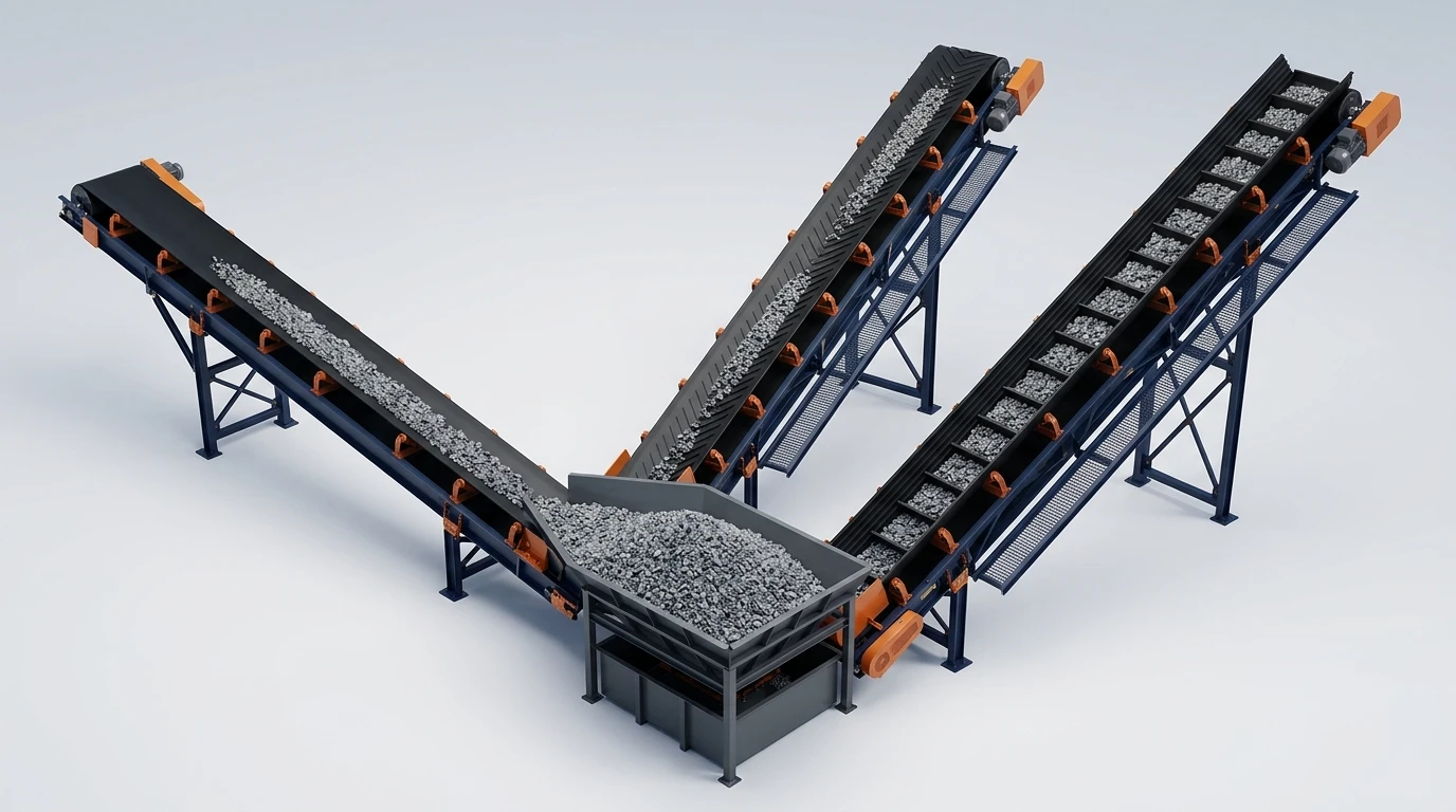
This workflow also protects against over-specification. A chevron conveyor belt is often the logical middle option when an incline is too severe for a plain cover but does not justify sidewalls and transverse pocket cleats. It still requires a profile matched to the material, plus a cleaning and transition plan that does not damage the cleats.
6. Do not let belt type hide the support, drive and transfer decisions
An incline selection changes more than the top cover. A chevron profile can limit the cleaner and plow arrangements that work safely. A sidewall belt changes the loading zone, support arrangement, return path, transition design and discharge approach. The higher the incline, the more important it becomes to review the complete system rather than a belt sample in isolation.
Carry-side support is especially important near the selected limit. Excess sag can disturb the material bed and make local behavior worse than the nominal conveyor angle suggests. It is worth checking the actual idler pitch and tension case rather than copying a spacing from a horizontal portion of the line. If the project also needs a new belt construction, review fabric conveyor belt options separately for carcass, cover, width, and pulley compatibility.
For steep systems, include the following questions in the RFQ:
- What material conditions were used to approve the angle, including the wettest and most free-flowing credible cases?
- Is the requested angle based on belt path or horizontal run, and does the general arrangement use the same basis?
- Which cleat or pocket geometry, belt speed, fill level and maximum lump size support the recommendation?
- How will the loading chute settle the material and prevent downhill tumble?
- Which head cleaner, return plow, pulley diameters, transition lengths and support components are compatible with the selected construction?
- What validation is proposed: comparable installation, material-on-belt testing, DEM-FEM analysis, or supplier calculation?
7. The practical answer: choose the lowest-complexity system that preserves margin
The best conveyor angle is not the largest angle a catalogue can show. It is the angle that moves the material reliably through its real operating range while preserving enough margin for moisture, feed variation, wear, starts, and maintenance.
Start with the layout angle and the least stable material condition. Keep a smooth belt where it has verified margin. Use a chevron or cleated design when mechanical retention solves a clearly defined shortfall. Move to corrugated sidewalls and pockets when the required geometry truly demands a steep-incline system—and validate the entire conveyor around that choice.
If you have the lift, belt-path length, material data and operating range, run a preliminary check in the Incline Angle Calculator and then request a belt selection review with the complete data sheet. That is a faster route to a defensible specification than choosing a construction from angle alone.