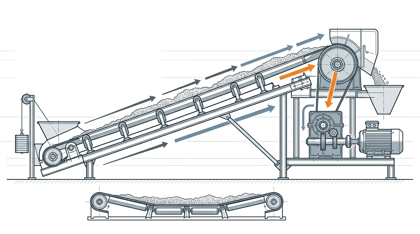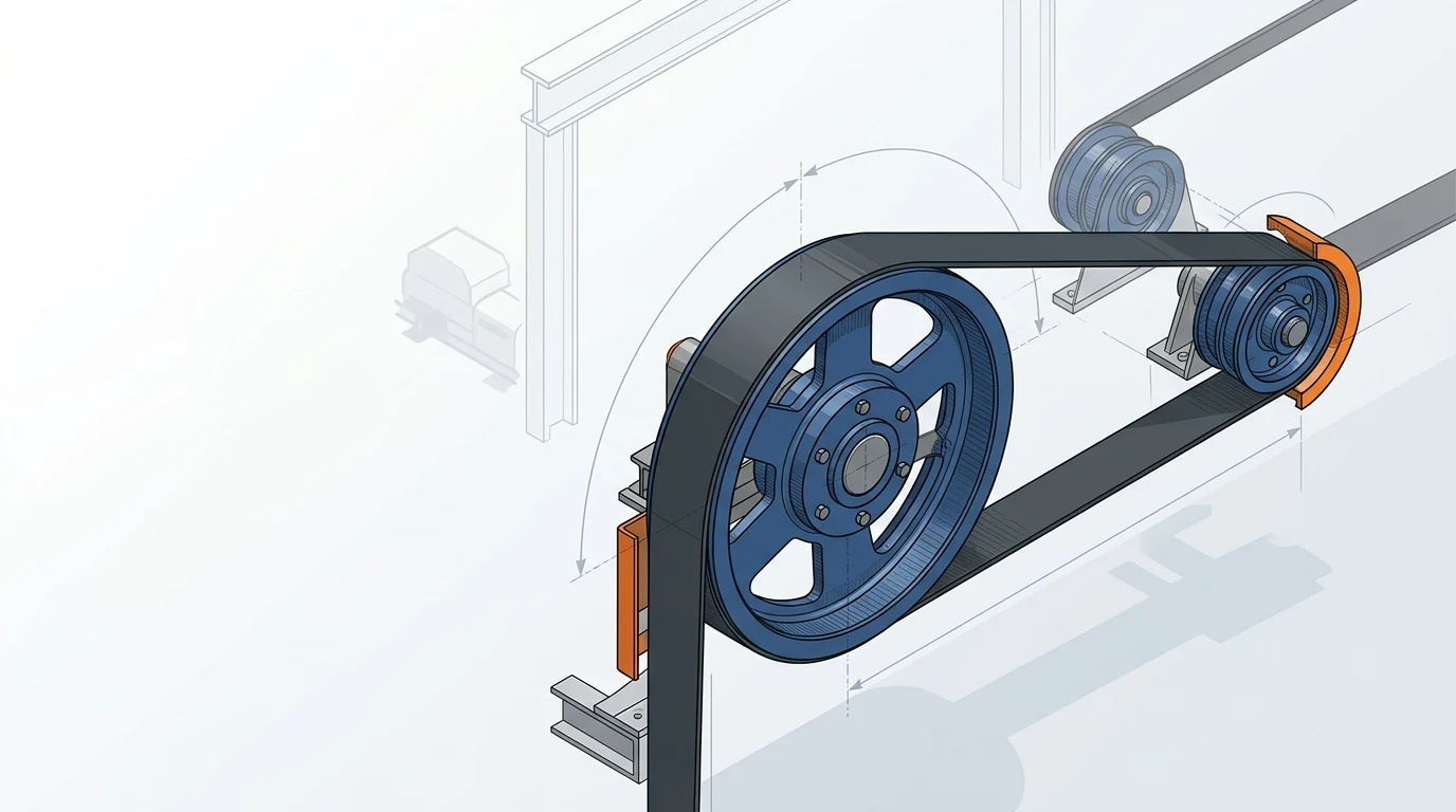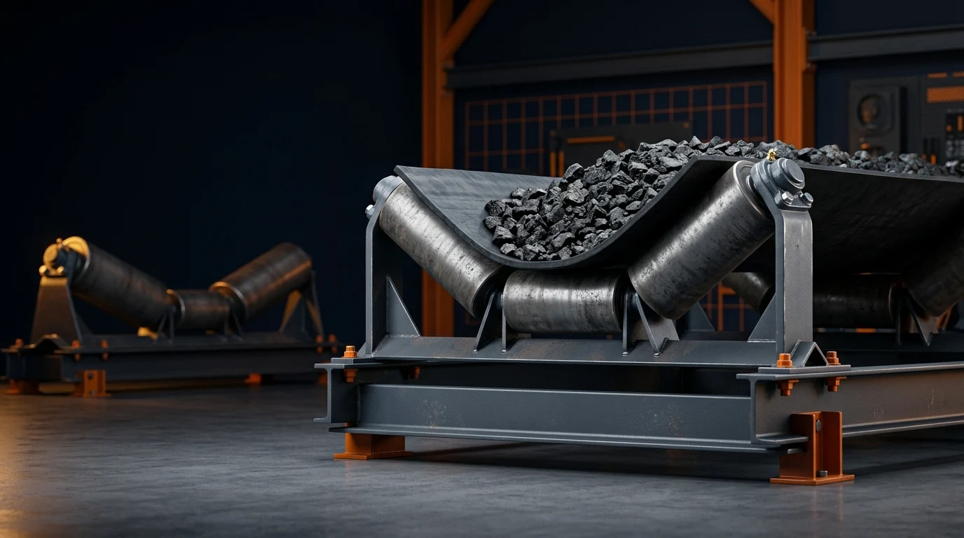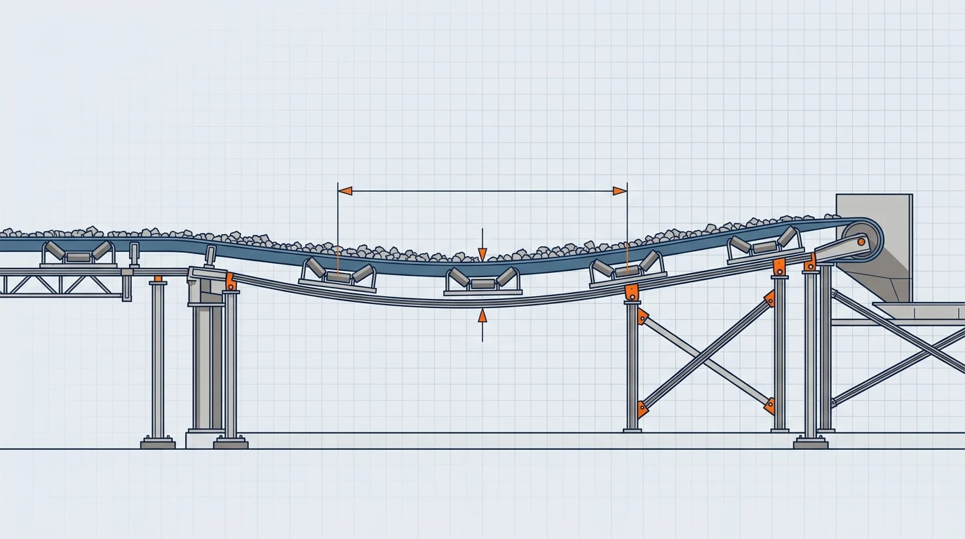
The short answer: set spacing from sag and local tension
For a bulk-material belt conveyor, idler spacing is not a fixed catalogue number. Start with an allowable belt sag percentage, then test the proposed idler pitch against the lowest belt tension at that span and the combined mass of the belt and material. If sag is too high, shorten the pitch, reassess the tension case, or change the support arrangement in that zone.
The practical order is simple: calculate sag for a trial spacing, separate carry run from the loading and return zones, then verify the low-tension operating cases before specifying idlers. A 1.2 m carry pitch that looks acceptable in a loaded steady-state calculation can be unsuitable under a skirtboard, during a transient, or where a local tension is much lower.
This guide is a first-pass workflow for conventional troughed conveyors carrying loose bulk material. It helps a design or maintenance team make the assumptions visible; it does not replace the responsible engineer’s complete CEMA, DIN or project-specific calculation package.
Collect the inputs before choosing a pitch
Sag is the vertical drop at the middle of the belt span between two idler sets. The number is useful only when each input describes the same operating point.
| Input | Symbol | Use the value from | Common mistake |
|---|---|---|---|
| Belt mass per length | m_b (kg/m) | Selected belt data | Using only the empty belt when the carry strand is loaded. |
| Material mass per length | m_m (kg/m) | Capacity ÷ belt speed | Using tonnes per hour directly without converting it to mass on the belt. |
| Combined mass per length | m_b + m_m | Sum for the actual case | Applying a full-load value to an empty return run. |
| Idler spacing | a (m) | Proposed centre-to-centre pitch | Using a nominal pitch while a special loading-zone pitch exists. |
| Local belt tension | T (N) | Tension diagram for that location and case | Substituting a drive-side or rated belt tension without checking the span. |
| Sag limit | S (%) | Project, application and support requirement | Treating a rule of thumb as a universal acceptance criterion. |
For a quick material-mass estimate in metric units:
m_m (kg/m) = capacity (t/h) × 1,000 / [3,600 × belt speed (m/s)]
That value is not the same as bulk density. Bulk density helps establish capacity and belt loading, but the sag formula needs the mass actually carried per metre at the selected throughput and speed.
Use the conveyor belt sag formula as a screening calculation
For a level, uniformly loaded span with relatively small sag, the BisonConvey calculator uses this screening relationship:
s (m) = [(m_b + m_m) × g × a²] / (8 × T)
Sag (%) = s / a × 100
Where g is 9.80665 m/s², a is idler spacing in metres, and T is the local tension in newtons. The relationship is important because sag rises with the square of spacing: a modest increase in pitch can create a disproportionately larger dip. Conversely, increasing local tension reduces sag, but it may shift load to the take-up, belt, pulley or drive and is not automatically the right correction.
Run the same inputs in the Conveyor Belt Sag Calculator rather than rebuilding unit conversions in a spreadsheet. It accepts belt speed, capacity, belt mass, idler spacing and tension, then reports sag depth and sag percentage. Its on-screen bands are a useful screening aid—up to 1%, 1–2%, and above 2%—but the final limit still belongs to the project requirement and the local conveyor condition.
The formula is deliberately a screening model, not a substitute for every conveyor analysis. It assumes a representative, supported span. Trough geometry, belt stiffness, concentrated loading, transition geometry, dynamic take-up response, acceleration and braking can all require a more complete calculation.
Worked example: test 1.2 m, then 1.0 m
Assume a 2.0 m/s conveyor moves 360 t/h. The selected belt weighs 20 kg/m. A tension diagram shows 5.0 kN at the carry-side location being reviewed. The team is considering a 1.2 m pitch in the normal carry run.
First calculate the material mass per metre:
m_m = 360 × 1,000 / (3,600 × 2.0) = 50 kg/m
Combined mass = 20 + 50 = 70 kg/m
Then test the trial pitch. Keep tension in newtons: 5.0 kN = 5,000 N.
| Step | At 1.2 m pitch | At 1.0 m pitch |
|---|---|---|
| Combined mass | 70 kg/m | 70 kg/m |
| Local tension | 5,000 N | 5,000 N |
| Calculated sag depth | 24.7 mm | 17.2 mm |
| Sag percentage | 2.06% | 1.72% |
| Interpretation | Above a 2% screening limit | Within a 2% screening limit |
The calculation does not say that 1.0 m is the right pitch everywhere. It says that, with these inputs and a 2% project criterion, 1.2 m needs a closer look and 1.0 m is the better starting point. The next questions are whether 5.0 kN is the minimum tension at that location, whether the load is uniform, and whether an even tighter pitch is required through a skirted loading zone.
If the result surprises the team, check units before changing hardware. The most frequent errors are entering belt tension in kN when a sheet expects N, mixing t/h with kg/m, or applying carry-side material mass to a return strand.
How much sag is acceptable?
There is no single percentage that safely fits every conveyor. Published CEMA-derived material commonly shows lower allowable carry-side sag as material lumps become larger, fines become less dominant or trough angle becomes more demanding. For example, Rulmeca’s explanation of the historical CEMA method presents 3%, 2% and 1.5% allowable-sag cases with different tension equations; it also notes that the tension requirement from sag must be compared with the traction requirement. See Rulmeca’s conveyor tension calculation guide for the original context and units.
Use a proposed limit as a documented design input, not as a label that makes a calculation final. A lower limit can be justified where material is prone to surge, where a skirt seal needs a stable belt line, where a belt scale is sensitive to deflection, or where a heavy/stiff belt is being supported. A less severe, controlled application may have a different approved criterion.
The useful question is: what does extra sag do at this span? If it lets material move under a skirt, flexes the belt aggressively over each set, increases cleaning problems or creates a visibly unstable line, the allowable sag is likely too high for that local duty even if a generic carry-run percentage looks familiar.
Set idler spacing by conveyor zone, not one plant-wide number
The idler spacing that works on a clean, fully loaded carry run should not be copied automatically to every zone. Divide the conveyor into support environments and check each one with its own mass, tension and functional requirement.
| Zone | What normally governs | Spacing approach | Extra check |
|---|---|---|---|
| Normal carry run | Loaded sag, station load and rolling resistance | Start with a trial pitch and calculate sag at the local running tension. | Confirm idler class and bearing life as well as sag. |
| Skirted loading zone | Belt flatness, impact and material containment | Use closer support than the normal carry run when the belt must stay stable under the seal. | Check drop height, lump size, loading centring and support continuity. |
| Transition near pulley | Belt geometry and edge tension | Follow the transition design; do not simply extend normal full-trough pitch to the pulley. | Check trough angle, belt construction and transition length. |
| Return run | Empty-belt sag, flutter and carryback | Calculate with belt mass and local return tension, which differ from the carry side. | Assess V-return or self-cleaning needs where appropriate. |
At a transfer, a belt can be within a normal carry-run sag target yet still move enough to open a skirt gap or bounce under impact. In that case, shortening a general carry pitch may not be sufficient. Review the loading geometry and consider impact idlers or another support arrangement that is rated for the actual impact and keeps the belt line stable through the seal. Do not use an impact idler as a substitute for correcting off-centre loading, excessive drop height or an undersized structure.
The same distinction applies to the return run. It carries no bulk material, so it often permits a wider pitch, but a light belt at a low local tension can still flutter or slap. Calculate the empty case separately rather than inheriting a spacing from the loaded strand.
Check the governing tension, not only normal running
The sag equation is sensitive to tension, so the tension used must be the smallest credible value at the reviewed span. This often requires more than one operating case.
Start by identifying how the belt-tension diagram was built. If that input is uncertain, first calculate conveyor belt tension from the conveyor geometry, resistances and drive arrangement. A motor nameplate, belt rating or a take-up setting is not automatically the correct span tension.
Then review at least the cases below:
- Loaded, steady running: normally the starting comparison for the carry strand.
- Empty running: changes the distributed mass and can change local tension patterns, especially on a long system.
- Starting and braking: transient tension waves can reduce tension in a zone even if the steady-state result is acceptable.
- Low-tension side and take-up condition: a sag requirement may govern take-up force; traction may govern elsewhere. Both must be satisfied.
- Changed duty: moisture, a new material, increased capacity, belt replacement or a modified chute can invalidate the old calculation.
Helix’s conveyor-analysis help provides a useful reminder that sag checks often include separate running, starting and braking thresholds, and that insufficient tension in a transient can require dynamic review rather than a simple static adjustment. See the Helix belt-sag result guidance for that software context.
Avoid “fixing” sag solely by raising take-up tension. Higher tension may reduce sag, but it can affect traction, splice margin, pulley loading and the allowable operating envelope. The safe decision is usually an iterative one: confirm the tension calculation, change spacing or support where appropriate, then recheck the complete system.
Troubleshoot the symptom without masking the cause
When a conveyor has spillage or unstable material at a support point, sag is a likely contributor but not the only one. Use the symptom to direct the first inspection.
| Symptom | Sag-related cause to test | Other cause that still needs checking |
|---|---|---|
| Material escaping beneath a skirt | Belt line dips between supports; pitch is too wide for the local load. | Off-centre loading, damaged skirt rubber, chute trajectory or worn liner. |
| Repeated belt cover wear over idlers | High sag causes repeated flexing and material agitation. | Seized rolls, buildup, abrasive material or incorrect belt construction. |
| Carry idler failures near a transfer | Tight pitch was not paired with the right impact/support rating. | Excessive drop energy, inadequate frame stiffness or idler class mismatch. |
| Empty belt flutter on return | Return tension and pitch allow excessive empty-belt sag. | Wind, carryback buildup, misalignment or missing V-return support. |
| Tracking changes after a spacing change | The belt line or loading condition changed with the new support layout. | Structure alignment, pulley condition and load centring. |
This separation matters because reducing pitch can hide a loading problem for a while while adding capital cost and resistance. Equally, replacing a skirt or adding a trainer will not restore a stable belt line if the local sag is the actual root cause.
Send a calculation-ready idler brief
Before changing the pitch or requesting a quote, record the inputs so another engineer or supplier can reproduce the decision:
- Conveyor layout, belt width, trough angle, speed and capacity range
- Belt construction, mass per metre, rating and splice type
- Material bulk density, maximum lump size, moisture, abrasiveness and expected loading pattern
- Proposed carry, loading-zone, transition and return pitches separately
- Local belt tension for loaded running, empty running and relevant transient cases
- Loading/drop height, skirtboard length and any existing impact support
- Required idler class, roll diameter, seal/environment duty and bearing-life target
- Inspection evidence: sag measurement, belt movement, spillage location, wear and failed-idler history
Use the Belt Sag Calculator to compare proposed pitches with the same inputs, then take the governing-case results into a review of the pulley and idler range. That gives the specification discussion a transparent starting point: not “use closer idlers,” but which zone needs which pitch, at which tension, and why.