The short answer: calculate running power from Te
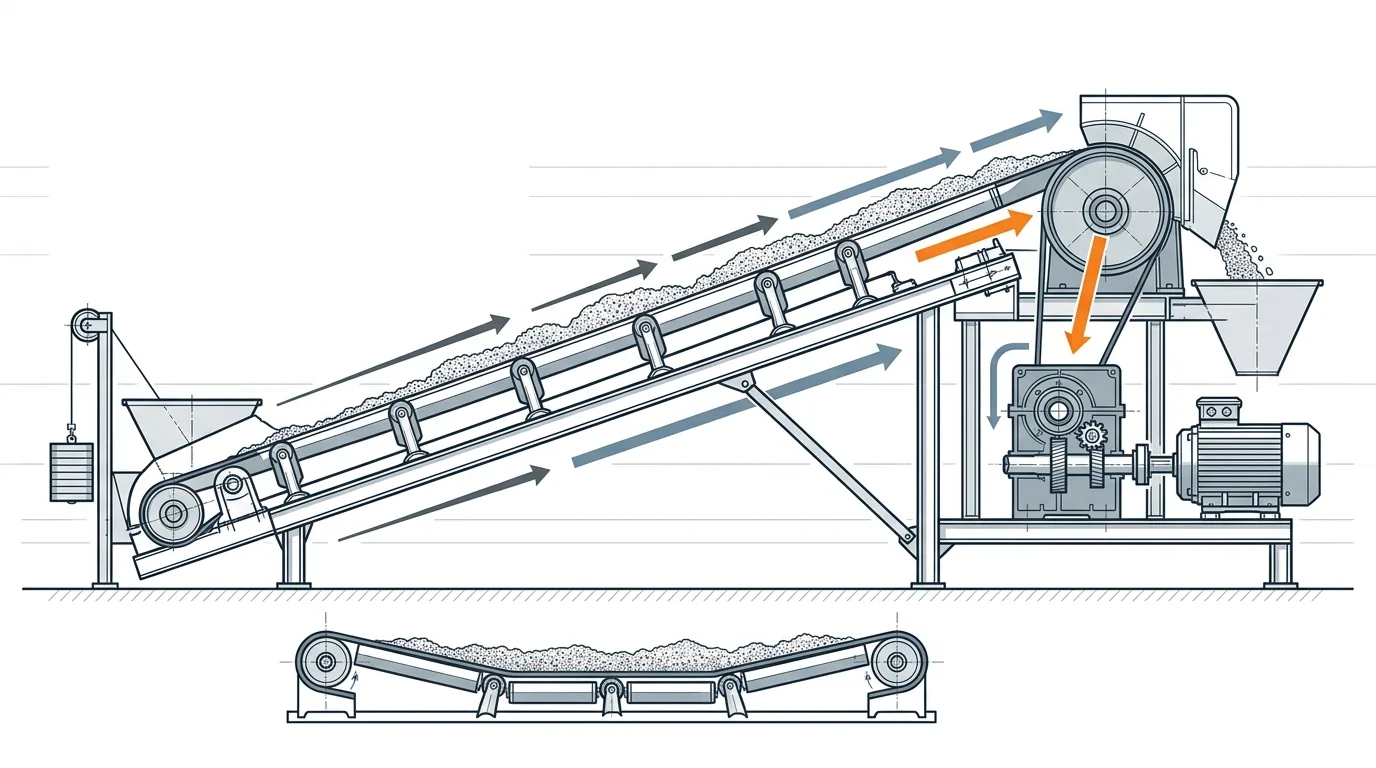
For a troughed bulk-material belt conveyor, start motor sizing with effective tension (Te), not with motor catalogue power. For steady running, mechanical power at the drive pulley is P_mech = Te × v; motor shaft power is P_motor = Te × v / η, where v is belt speed and η is drive-train efficiency. Then check starting torque, duty cycle, braking/regeneration, gearbox rating and pulley traction before choosing the final motor.
That distinction matters. A 55 kW motor may be the right next standard size for a 50 kW running-power estimate, yet still be a poor final choice if the starting method cannot accelerate the loaded belt, the reducer overheats at the selected ratio, or the drive pulley cannot transmit the required Te without slip.
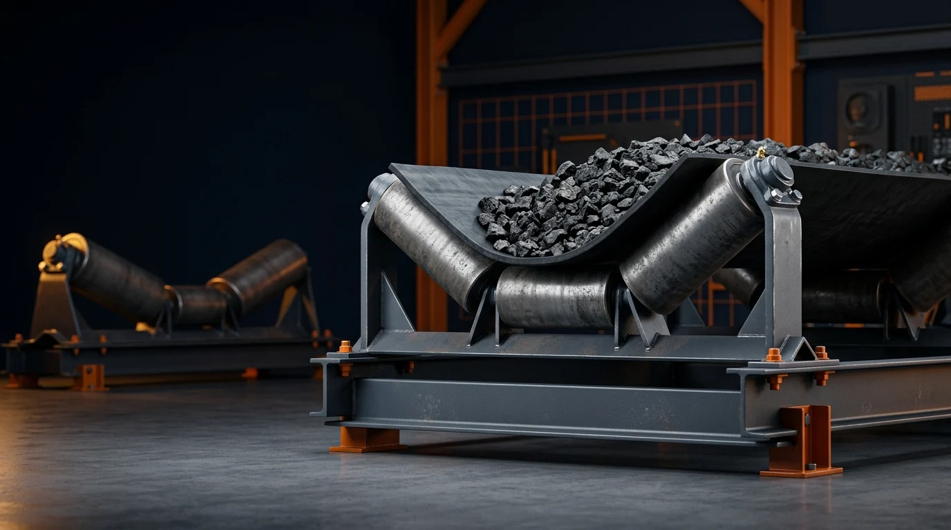
This guide is for conventional belt conveyors carrying loose bulk material on idlers. It is a first-pass engineering workflow, not a substitute for a project calculation package or the responsible engineer's final review.
Start with the inputs that can change the answer
The motor calculation is only as good as the resistance model behind it. DIN 22101 applies to belt conveyors for loose bulk materials and provides a basis for calculating and dimensioning the belt, drives, brakes and take-up devices. ISO 5048 similarly defines methods for calculating operating power and tensile forces for belt conveyors with carrying idlers. See the published scopes from DIN Media and ISO before treating either name as a generic formula label.
For a preliminary calculation, collect the following before opening a calculator or spreadsheet:
| Input | Why it affects power | Practical note |
|---|---|---|
| Effective tension, Te (N or kN) | It is the net force the drive must transmit. | If Te is not known, first estimate it with the belt tension calculator. |
| Belt speed, v (m/s) | Power rises directly with speed for the same Te. | Use the design operating speed, not a nominal catalogue speed. |
| Drive efficiency, η | Losses between motor shaft and pulley increase required motor input power. | Confirm the actual motor, coupling, reducer and auxiliary-drive arrangement. |
| Starting and acceleration duty | A steady-state result does not include every transient force. | Record loaded/unloaded starts per hour, acceleration time and start method. |
| Conveyor geometry and material | Lift, resistance, belt mass and material mass create Te. | Verify capacity, bulk density, length, lift and special resistances. |
| Drive layout | One drive, multiple drives, wrap angle and lagging affect traction and torque sharing. | Treat it as a system check, not a motor-only check. |
Build Te before you calculate kW
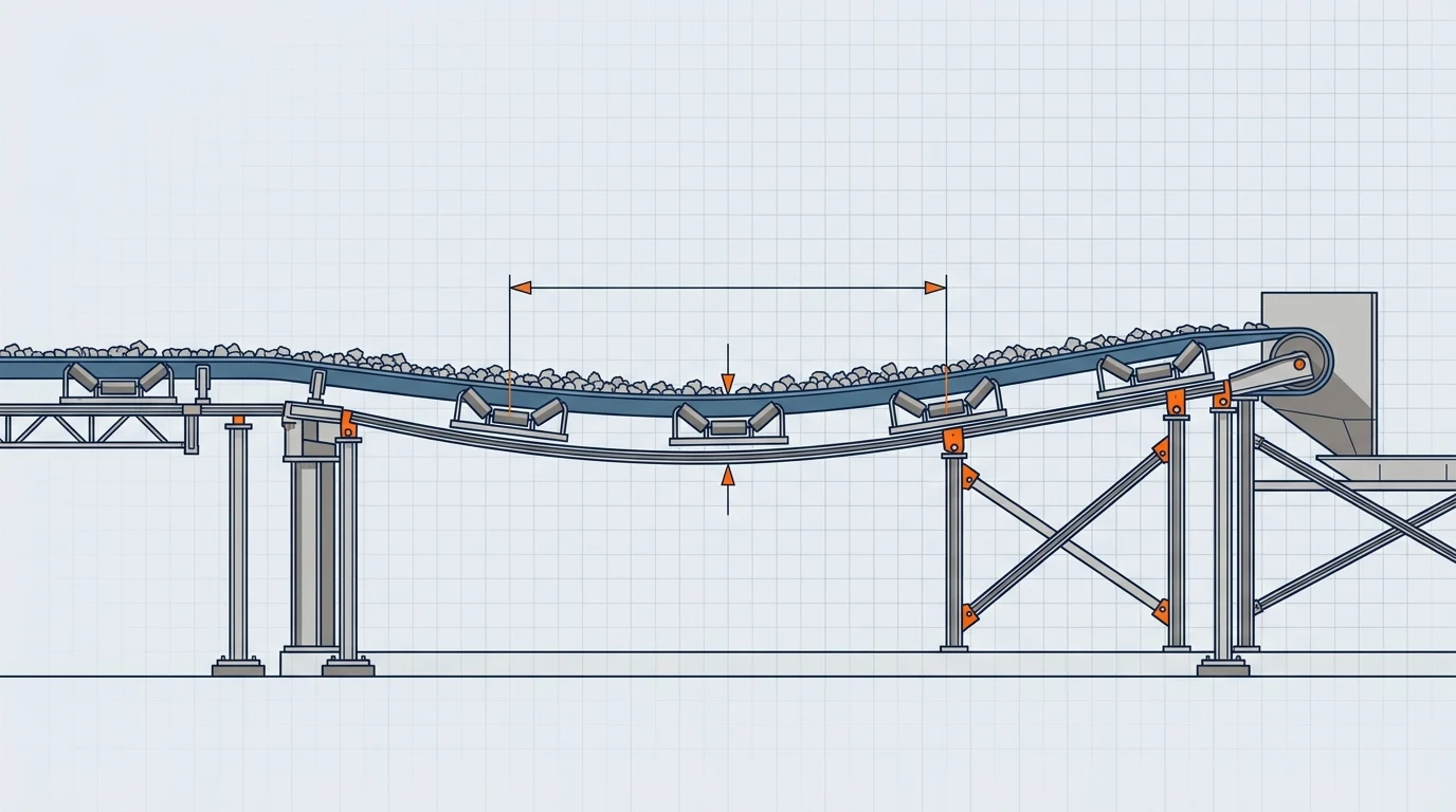
For a simple conveyor, it is tempting to start with throughput and multiply by a rule of thumb. That hides the forces that actually govern the drive. A DIN-style resistance model first accounts for the main resistance of the moving belt and material, then elevation resistance, then the secondary and special resistances created by items such as loading points, cleaners, ploughs, curves or trippers. The resulting Te is the force the drive must transmit at the operating point.
Use this sequence when preparing a first estimate:
- Define the operating case: capacity, belt speed, center distance, lift and material condition.
- Calculate Te for that case using a consistent resistance method; do not mix coefficients from unrelated methods.
- Convert Te and speed to pulley power.
- Divide by a documented transmission efficiency to obtain a running motor-power estimate.
- Carry Te, torque and pulley rpm into the drive, belt and traction checks.
The result is more useful than a bare kW number because another engineer can trace each assumption. It also reveals where better site information matters most. For example, a long horizontal conveyor may be sensitive to the assumed rolling/friction resistance; a high-lift conveyor may be dominated by elevation; a short conveyor with multiple accessories can be dominated by secondary resistance. In each case, changing the wrong input can produce a plausible-looking but misleading motor size.
For conventional systems, CEMA material similarly separates belt tension and power engineering from later component checks. The practical point is the same: a preliminary horsepower result is not enough for complex layouts, decline sections or high-capacity applications.
Turn effective tension into motor shaft power
Once the resistance calculation produces Te, the power conversion is straightforward if the units stay consistent:
P_mech (kW) = Te (N) × v (m/s) / 1000
P_motor (kW) = P_mech / η
P_mech is the mechanical power delivered at the drive pulley. P_motor is the approximate power that must arrive at the motor shaft after allowing for transmission losses. Do not divide by an assumed efficiency and call the result a final nameplate selection; it is the running-power requirement under the stated assumptions.
Efficiency needs a source. A helical reducer, a fluid coupling, an open gear, a belt drive, a VFD and a multi-motor arrangement do not all have the same losses. If the project has no verified efficiency, document the assumption and test the sensitivity. A change from 0.90 to 0.85 raises a 45 kW pulley-power requirement from 50.0 kW to 52.9 kW at the motor shaft.
For a quick, transparent first pass, use the Conveyor Motor Power Calculator. It returns Te, pulley mechanical power, estimated motor shaft power and the next standard IEC size from capacity, geometry, belt mass, friction factor and efficiency. Its result should initiate the selection discussion; it does not replace the final dynamic or component checks.
Keep torque and speed visible
Power can look correct while the selected drive still has the wrong speed or torque. At the drive pulley:
T_pulley (N·m) = Te (N) × pulley radius (m)
n_pulley (rpm) = 60 × v / (π × pulley diameter)
These two values connect the belt calculation to reducer ratio and mechanical rating. They also make unit mistakes visible: multiplying kN by m produces kN·m, so convert Te to N before recording torque in N·m.
Worked example: 18 kN at 2.5 m/s
Assume a bulk-material conveyor resistance calculation has already established Te = 18 kN at a design belt speed of 2.5 m/s. The drive train has an assessed efficiency of η = 0.90. These are illustrative inputs, not BisonConvey performance data.
| Step | Calculation | Result |
|---|---|---|
| Convert Te | 18 kN × 1,000 | 18,000 N |
| Mechanical power at pulley | 18,000 N × 2.5 m/s / 1,000 | 45.0 kW |
| Estimated motor shaft power | 45.0 kW / 0.90 | 50.0 kW |
| Preliminary standard motor step | Select the next available IEC rating above the estimate | 55 kW, subject to checks |
If the drive pulley diameter is 500 mm, its radius is 0.25 m. The corresponding pulley torque is 18,000 × 0.25 = 4,500 N·m. At 2.5 m/s, pulley speed is approximately 60 × 2.5 / (π × 0.5) = 95.5 rpm. Those two results—not just the 55 kW figure—belong in the reducer selection request.
Notice what this example does not do. It does not silently add a universal service factor, select a reducer ratio, establish the acceleration time, prove belt traction, or declare the 55 kW motor compliant with a project standard. Those decisions depend on the operating case and the supplier rating data.
If you still need to develop the force side of the example, use the separate step-by-step guide to conveyor belt tension. That guide owns the Te build-up and T1/T2 logic; this article owns the next step from Te to the drive.
Do not turn the next IEC size into an automatic final selection
Rounding an estimated shaft-power value up to the next IEC rating is useful for a budget estimate. It is not a complete motor-selection method. Before finalizing the motor and reducer, review the cases that change the governing requirement.
Check the worst operating case, not only full-load running
List the cases the conveyor must survive: loaded start, empty start, normal running, material surge, coast-down, emergency stop and any downhill or regenerative condition. The worst case may be a transient rather than continuous operation. Long conveyors, high-lift conveyors, conveyors with multiple drives, and systems with fast start/stop requirements often need a dedicated dynamic analysis.
The correct question is not “what service factor should I add?” It is “which load case governs motor torque, reducer thermal rating, belt tension and control method?” A single blanket margin can hide a missing load case. Record the start method as well—direct-on-line, soft starter, VFD or controlled coupling changes the torque and acceleration behavior the rest of the system sees.
Also separate motor overload capability from system acceleration. A motor may produce enough temporary torque while the belt, splice, take-up or drive pulley sees an unacceptable transient tension. Conversely, a conservative fixed-speed motor selection can be unnecessarily large if a controlled acceleration profile materially reduces the transient. The calculation package should state which variables were modeled and which remain an OEM/control-system review item.
Match motor speed, reducer ratio and thermal rating
Use pulley rpm and required pulley torque to select a ratio that reaches the target belt speed at the motor's intended speed. Then check the reducer's mechanical rating, allowable output torque, thermal rating, mounting position, lubrication, ambient temperature and duty cycle. The conveyor reducer and gearbox selection guide provides the follow-on checks in more detail.
Treat decline conveyors separately
On a decline conveyor, gravity can reduce running motor demand or drive the conveyor. That does not mean the drive is “easier” to select: braking, holdback, regeneration and emergency-stop behavior may become the governing design concerns. Do not use a positive-lift example unchanged for a decline application.
Verify the drive pulley can transmit the calculated Te
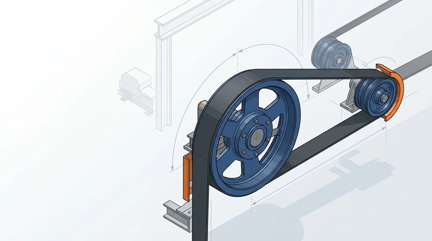
The motor supplies torque, but the drive pulley must transfer that torque to the belt through friction. Te relates to tight-side and slack-side belt tensions by Te = T1 − T2; the allowable ratio is governed by wrap angle and the belt-to-lagging friction condition. Water, carryback, worn lagging and insufficient wrap can reduce the real traction margin even when the power calculation is correct.
This is why motor sizing should hand off a complete set of results—Te, pulley torque, belt speed, T1/T2, wrap angle, lagging condition and starting case—to the pulley and drive designer. The pulley traction and wrap-angle guide explains how wrap, lagging and drive arrangement affect that check.
For high-power or difficult-duty applications, a single larger motor is not always the answer. The final solution may require another drive pulley, a different lagging choice, changed wrap, a different reducer, a revised acceleration profile or a different control strategy. Solve the governing limit rather than adding kW by habit.
Send a complete drive-selection brief
For an RFQ or engineering review, provide enough information for the drive package to be checked as a system:
- Conveyor center distance, lift profile and pulley diameters
- Material name, bulk density, capacity range, lump size, moisture and abrasiveness
- Belt construction, width, mass per metre, rating and splice type
- Design speed plus desired acceleration and deceleration times
- Te for each operating case, along with T1/T2 where available
- Drive arrangement, wrap angle, lagging type and number of drives
- Start/control method, starts per hour, duty cycle and ambient conditions
- Any braking, backstop, downhill or regeneration requirement
- Project standard, electrical supply and required motor protection class
Use the Motor Power Calculator to produce a transparent preliminary result, then request a drive-pulley specification review with the full operating brief. That sequence keeps a useful estimate from becoming an unsupported final selection.