A copper mine does not need a generic “copper belt.” It needs a conveyor system matched to the route that its ore actually follows: mine and crushing, then either a heap-leach stack or a concentrator feed route. Material size, moisture, elevation, transfer frequency and required availability can change several times before copper leaves the site. If those changes are not recorded by conveyor zone, a belt specification can look plausible on paper and still fail at the loading zone, take-up or transfer chute.
This guide is for mined ore handling, not copper-wire recycling equipment. Its purpose is to turn a copper flowsheet into a practical conveyor brief for concept design, retrofit scoping and supplier RFQs.
Start with the copper mine conveyor route, not the belt catalogue
The first design question is not whether to buy fabric or steel cord. It is: where does this conveyor sit in the process, and what reaches it? Copper ore may be coarse and impact-heavy after primary crushing, damp and cohesive after conditioning, or a controlled fine product near a concentrator. Each state imposes a different dominant risk.
Two broad processing branches make this visible:
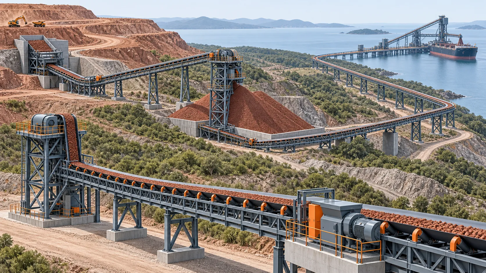
- Heap-leach route. Crushed ore is conveyed and stacked on a prepared pad. The U.S. EPA’s copper mining overview describes crushing and stacking copper-bearing ore on lined pads before solution is applied and collected. Here, conveying must preserve a controllable heap feed while managing moisture, fines, carryback and the operating envelope around the pad.
- Concentrator route. Crushed ore is sent through stockpiling and onward to grinding and separation. The route is normally defined by sustained plant feed, surge control, reliable transfer points and close control of mass flow. TAKRAF’s copper process overview distinguishes crushing, conveying and concentration, while its Mina Ministro Hales reference shows an in-plant system handling ore, pebbles and steel balls across multiple conveyors and transfer towers.
The branches may share a mine-to-crusher conveyor, but they should not automatically share one belt construction or one cover specification. Oxide versus sulfide mineralogy can help explain the chosen metallurgical route, but it does not by itself size a conveyor. The design inputs are the conveyed material and duty at each individual location.
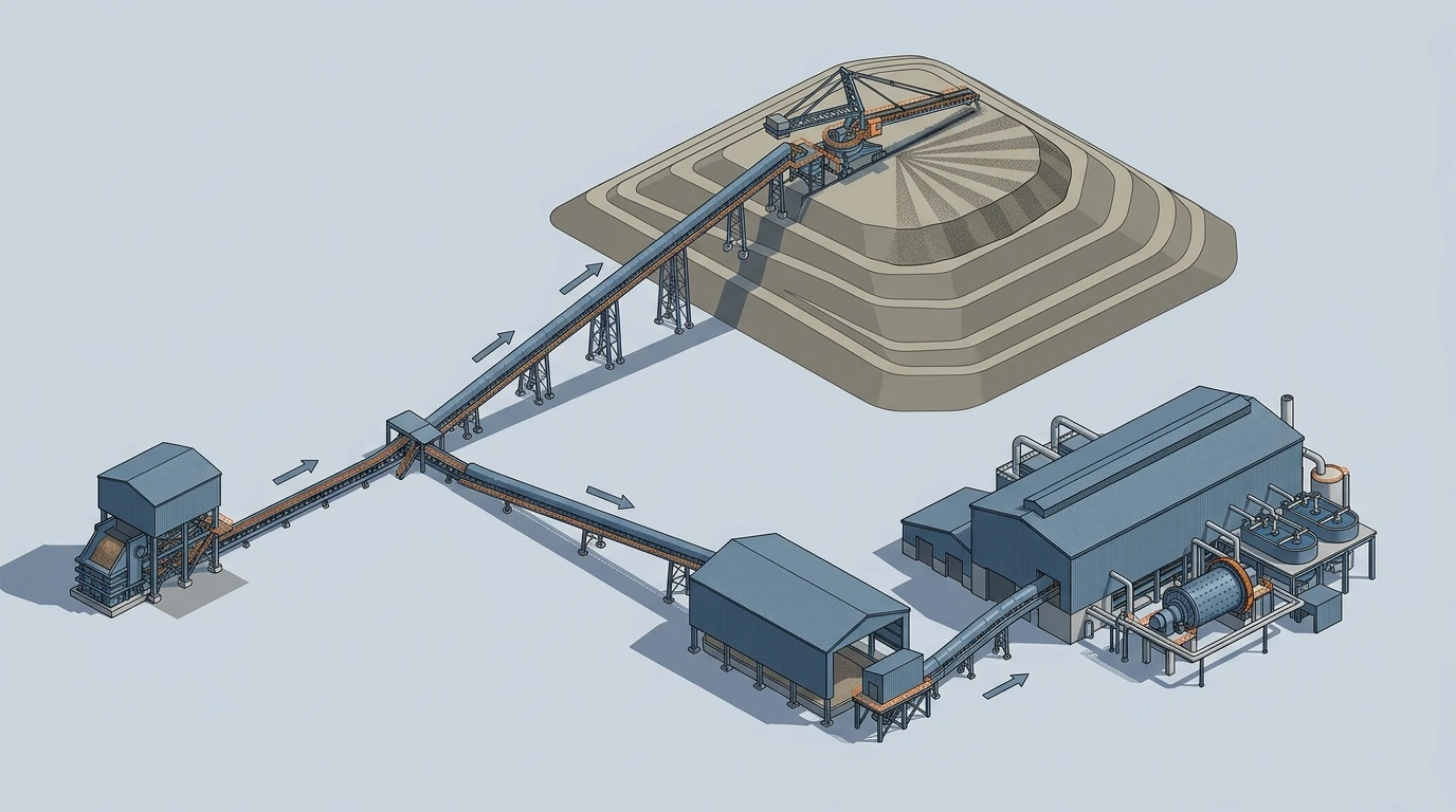 A route-first view makes the physical split between heap-leach stacking and concentrator feed visible before components are specified.
Map the flowsheet into conveyor zones
Make a one-line record for every flight before choosing a belt. A useful zone map has five common groups.
| Zone | Typical material state | What usually controls the design | Question to settle before RFQ |
|---|---|---|---|
| Mine / primary-crusher feed | Run-of-mine or coarse crushed ore; wide size distribution | Impact, cut-and-gouge damage, feeder interface | What is the true top size, maximum lump mass and drop condition? |
| Crusher discharge / coarse-ore stockpile | Crushed ore, possible surge loading | Throughput range, belt loading, dust and transfer impact | What is normal versus peak feed, and how long must the stockpile decouple the circuit? |
| Heap-leach preparation and stacking | Crushed, sometimes conditioned or agglomerated ore | Moisture, cleanup, grade control, mobile/shiftable discharge | What moisture and solution-exposure conditions reach the belt, cleaners and structure? |
| Concentrator feed and in-plant transfer | Controlled crushed ore, pebbles or reagents depending on point | Availability, weigh control, transfer containment | What are the planned and unplanned shutdown consequences of one flight stopping? |
| Concentrate, tailings or reclaim handling | Material state varies widely after processing | Moisture, adhesion, corrosion environment and containment | Is this still a belt-conveyor duty, or does filtration/pumping change the material-handling method? |
Do not fill this table with annual mine output. Belt capacity is governed by the peak hourly mass rate, bulk density, belt width, speed and loading geometry. Annual tonnes help the business case; they do not establish the load carried by one metre of belt.
The zone sheet should also state operating hours, elevation profile, horizontal and vertical curves, ambient temperature, dust-control requirement, inspection access, and whether the line has a bypass or spare path. These are not “later” details. They decide whether a line is a simple in-plant conveyor or a high-consequence trunk system.
Match the conveyor configuration to the zone
Once the route sheet is complete, select in layers. First establish capacity and geometry; then calculate tension; then select carcass, covers, pulleys, idlers and transfer hardware as one system.
Short and moderate-tension transfers. Many crusher, stockpile and in-plant flights can start with a fabric conveyor belt construction. The important qualification is not that fabric is light duty. It is that its allowable rating, elongation, splice method and pulley compatibility must satisfy the calculated tension case. A coarse ore line can still need a robust top cover, impact support and a stronger carcass than a nearby fines transfer.
Long, high-tension or high-lift routes. Where centre distance, elevation and sustained mass flow create high tensions or constrained take-up travel, steel cord belt construction becomes the natural option to evaluate. It offers low elongation, but it also moves the discussion to splice quality, inspection access, drive arrangement and damage detection. The Chuquicamata reference is a useful scale illustration, not a template to copy: it describes crushed ore moving through underground and overland sections with major elevation change before surface processing. A normal project needs its own resistance, starting and braking cases.
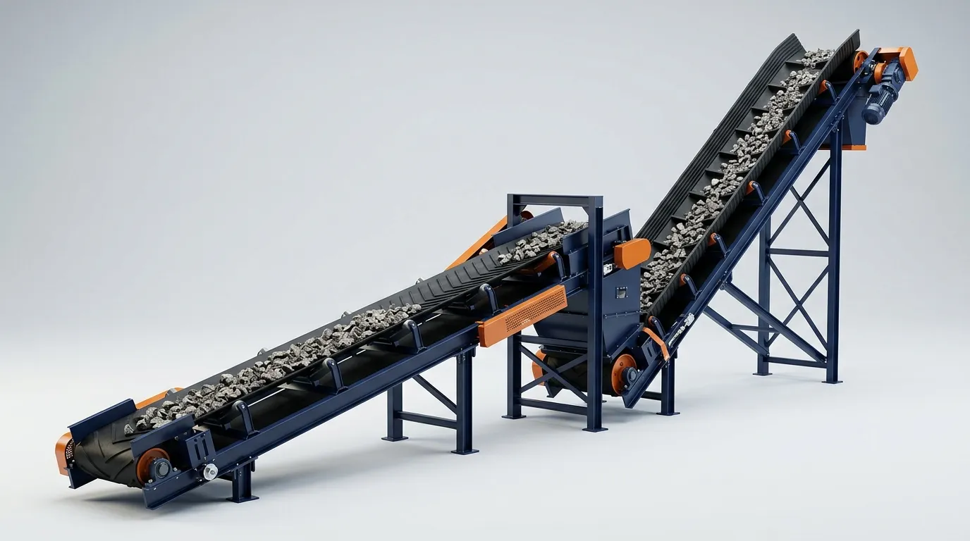
Steep lifts and pad geometry. A sidewall or pocketed solution may be appropriate when a route has a genuine footprint constraint, but it should not be used to avoid checking material retention, feeding and cleaning. Fine, damp or variable ore can change how a steep system behaves. Confirm the actual incline, belt speed, cleat/pocket geometry and discharge arrangement with the conveying engineer rather than selecting a maximum-angle product from a catalogue.
Cover compound is a separate decision. Carcass strength answers “can the belt carry the tension?” The cover answers “can it survive the material and the interface?” For copper-ore flights, record abrasion, sharpness, fines content, temperature, moisture, any chemical contact and the condition of chute liners and cleaners. A thicker or more abrasion-resistant cover cannot compensate for a damaging loading trajectory; equally, a correctly engineered chute cannot rescue a cover that is too thin for the wear duty.
Treat every transfer as a belt-life component
On a copper route, the most punishing point is often not the long conveyor. It is where material leaves a crusher, feeder or preceding belt and arrives on the next one. Our belt conveyor transfer-chute design guide explains the underlying trajectory, impact and containment checks in more detail.
The receiving belt needs a stream that is centred, controlled and moving in approximately its intended direction. When a transfer drops material from too high, changes its direction abruptly or deposits it off-centre, the consequences compound: impact damages the cover and carcass; sliding wear consumes rubber; fines escape as dust; and off-centre loading drives mistracking. The same location can create carryback that later contaminates return idlers.
Review each transfer with this sequence:
- Define the upstream material trajectory from the actual belt speed, head pulley and discharge geometry.
- Check the receiving-belt speed and direction, then reduce the mismatch through chute geometry rather than expecting the belt to absorb it.
- Set the impact zone: support, idler spacing or an impact bed, cover thickness and accessible wear liners must work together.
- Give the material a settling length before the skirt seal ends, and retain a clean belt edge for sealing and tracking.
- Plan cleaners, dribble collection and access before steelwork closes the area.
This matters especially around heap-leach stacking, where wet or conditioned fines can reveal small cleanup problems quickly, and around concentrator feed, where an avoidable stoppage can starve downstream equipment. The project record for Mina Ministro Hales includes multiple transfer towers and complete chute arrangements—an appropriate reminder that transfers are engineered equipment, not empty space between belts.
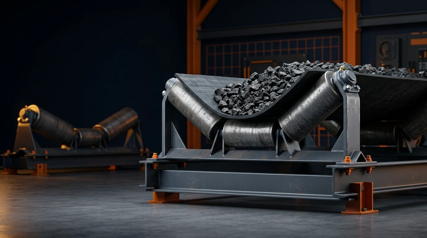
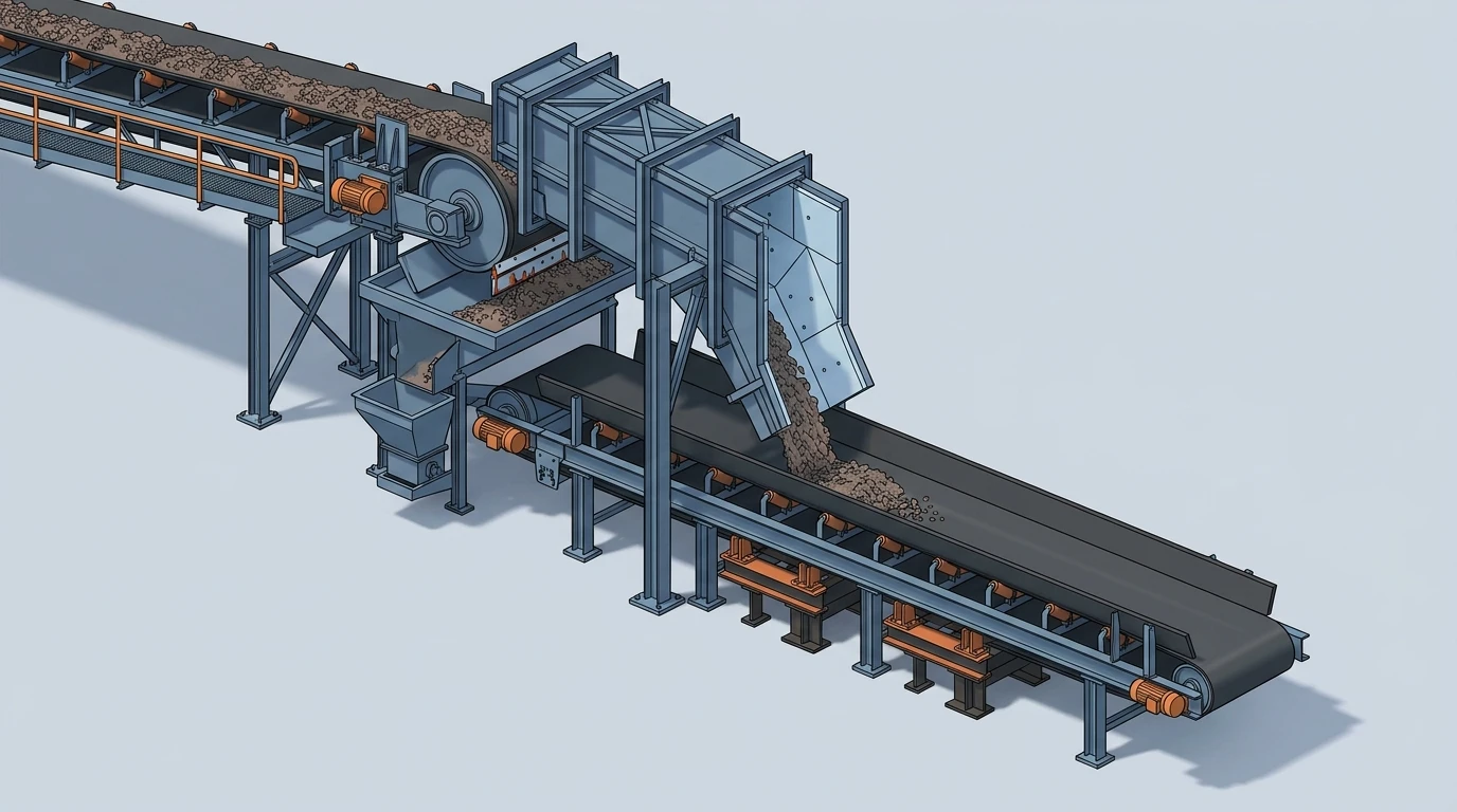 The transfer assembly shows the components that must be considered together: controlled loading, impact support, sealing, cleaning and dribble collection.
Convert the route into capacity, tension and power cases
Calculations should proceed in a disciplined order. Start with the material and capacity case, then build the resistance and tension model, then size drives and confirm the selected belt construction against the highest relevant operating and transient condition.
- Capacity case. Establish design t/h, bulk density, surcharge assumptions, belt width, speed and expected loading profile. Run normal and peak feed cases separately if surge operation is part of the route.
- Resistance and tension case. Add lift, length, idler rolling resistance, curves, skirt friction, cleaners and any special equipment. Check running, starting, stopping and adverse loading cases—not just a steady, level conveyor. Use the belt tension calculator for a transparent preliminary case, then validate the final design with the project method and supplier data.
- Take-up and splice case. Verify the required take-up travel for the selected carcass and confirm the proposed splice method, installation conditions and inspection plan.
- Drive and control case. Match motor, pulley, braking and control philosophy to the route. Long downhill or high-lift lines deserve a dedicated dynamic review; a preliminary power result is not a substitute for it.
Large published projects show how quickly the interaction between route geometry and controls becomes complex. Their project-specific ratings should not be scaled down by rule of thumb; use the example only to reinforce the principle that route geometry and control strategy must be considered together.
The final design should be checked to the applicable project standard and supplier data. A calculator is valuable for a transparent first pass, but it cannot validate every transient, structural, pulley, splice or chute detail in a mine-specific system.
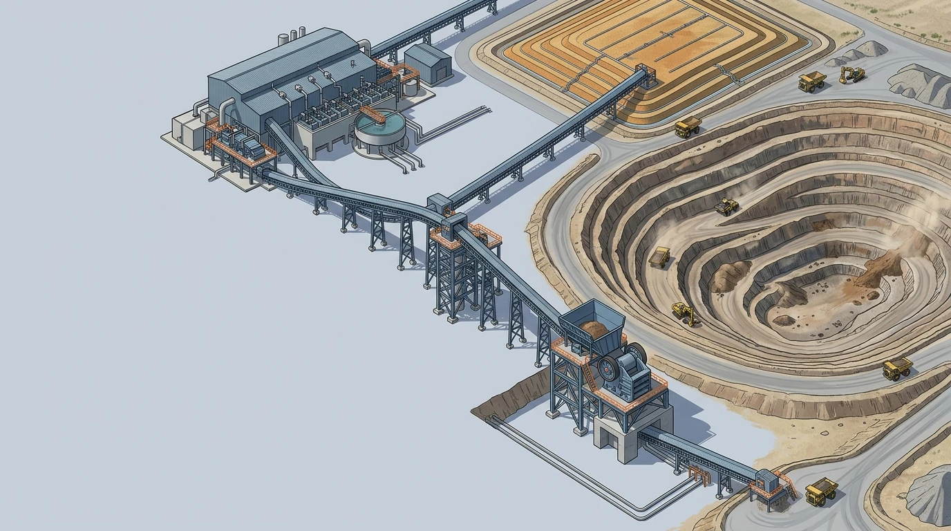
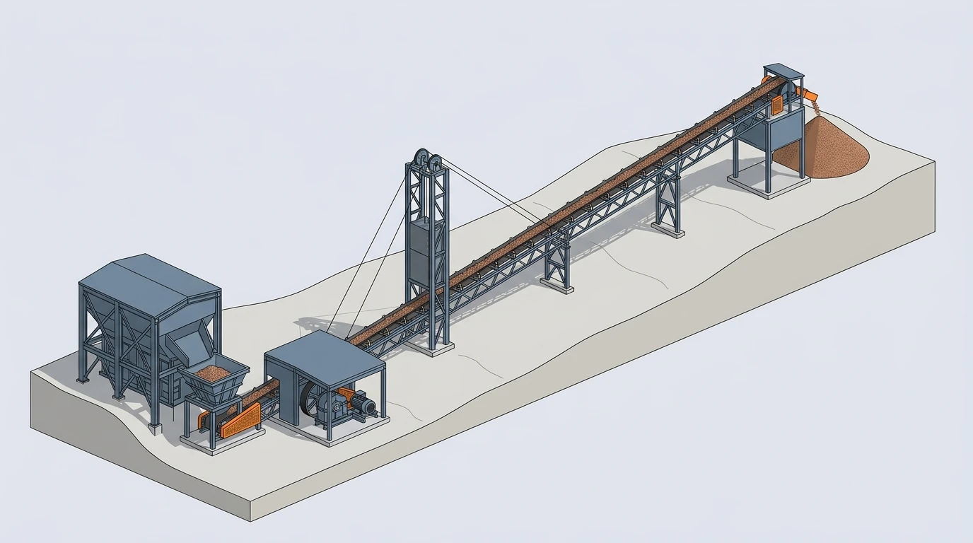 Route geometry, drive arrangement and take-up travel belong in the same design case rather than being selected independently.
Issue an RFQ that suppliers can compare
A quote request that says “copper conveyor belt, 1,200 mm” invites every supplier to make a different assumption. Instead, issue a short data sheet for each flight:
- conveyor purpose and flowsheet location;
- material description, bulk density range, top size, fines and moisture;
- normal, design and surge throughput;
- centre distance, lift, route profile, belt width and speed target;
- calculated tension cases, take-up arrangement and requested carcass evaluation;
- top/bottom cover performance and thickness requirements tied to abrasion, cut/gouge and exposure;
- loading, transfer, impact-support, cleaning and containment requirements;
- ambient conditions, access constraints, shutdown window and required availability;
- governing standards, inspection documents, splice scope and acceptance criteria.
Ask suppliers to identify their assumptions and exceptions against the same sheet. That produces comparable bids and exposes whether the difference is price, belt construction, cover, splice scope, drive philosophy or an omitted transfer requirement.
The practical next step
For a copper mine conveyor system, start by drawing the actual route and writing a zone sheet before choosing any belt family. Treat the heap-leach branch and concentrator branch as different material-handling problems, even if both begin with the same crushed ore. Then use capacity, tension and power calculations to test the route, and carry transfer, cleanup and splice requirements into the RFQ.
That order avoids the most expensive shortcut: selecting a catalogue belt first and discovering later that the process route demanded a different conveyor system.