A bauxite conveyor belt is not selected simply because the ore is called bauxite, or because the route is long. The right specification starts with the condition of the material at each conveyor flight: coarse and impact-heavy after crushing, fine-rich and wet at a transfer, or steady bulk flow on an overland route. Those conditions determine whether the controlling problem is cover wear, carryback, belt tracking, tension, take-up travel or drive control.
For a concept design, retrofit or belt RFQ, treat the process route as the design brief. This guide shows how to turn it into a practical selection sequence without treating a published mine project as a universal belt specification.
Start with the bauxite conveyor belt route, not a belt grade
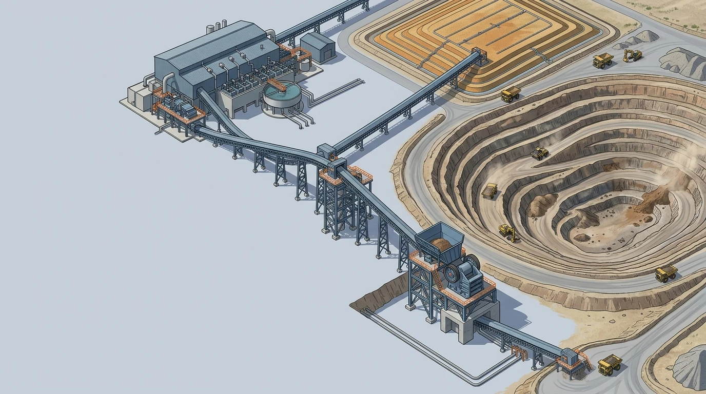
The first useful question is not “fabric or steel cord?” It is where does this conveyor sit, and what material reaches it? In a typical operation, bauxite is excavated, taken to crushing, reduced to a transportable size, and then sent by conveyor or rail to a refinery or a shipping terminal. The Australian Aluminium Council’s bauxite-mining overview outlines that mine-to-crusher-to-refinery-or-terminal sequence.
That sequence often contains more than one conveyor duty. A mine or primary-crusher interface can see wide particle-size variation and high impact. A stockpile discharge may see variable feed and surging. A long line to a terminal may be dominated by tension, elongation, terrain and availability. The same material can become more adhesive after rainfall, conditioning or fines buildup, which changes the burden on cleaners, return-side housekeeping and transfer seals.
Whether the procurement brief calls it an aluminium ore conveyor or a bauxite mining conveyor, the selection logic is the same: describe the duty of each flight before asking for a belt construction. “Bauxite handling conveyor” is a useful project label, but it cannot substitute for the material and route inputs below.
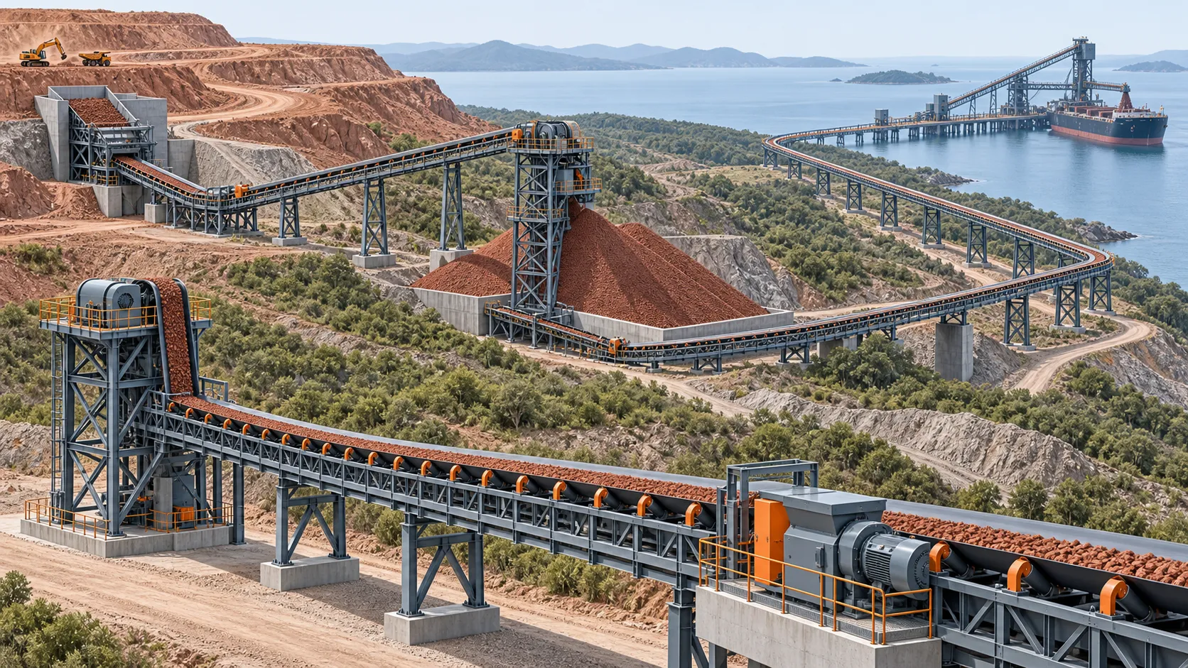
Published installations reinforce the importance of route geometry, but they should not be copied as design values. For example, a Jamaica bauxite RopeCon reference describes a 7.2 km enclosed mine-to-port system. It is evidence that bauxite routes can be long and constrained by terrain; it is not evidence that every bauxite operation needs a suspended or cable-supported conveyor.
For the broader decision sequence that applies across mining duties, see this mining conveyor belt selection guide. This article stays focused on the route and material conditions that make bauxite handling distinct.
Before selecting components, make each flight answer four questions:
- What is the material’s top size, fines content, moisture range and bulk-density range at this point?
- What is the normal, peak and surge mass flow, rather than only annual production?
- What are the route length, lift, curves, loading condition and take-up constraints?
- What is the consequence if this conveyor stops, and is there a bypass, stockpile or spare path?
This turns “we need a bauxite belt” into a design statement that a conveyor engineer and belt supplier can actually evaluate.
Map the route into conveyor zones
Create one short record for every conveyor flight. The material description should be measured or confirmed for that flight, not inherited from a general mine data sheet. The following zone map is a useful starting point.
| Conveyor zone | Typical material state | Dominant design risks | Input that must be settled |
|---|---|---|---|
| Mine and crusher feed | Run-of-mine or coarse crushed bauxite; variable lump size | Impact, cut-and-gouge damage, feeder interface, off-centre loading | True top size, maximum lump mass, drop height and loading trajectory |
| Crusher discharge and stockpile feed | Crushed material, often with fines and changing feed rate | Cover wear, throughput variation, dust and transfer impact | Normal versus surge rate, particle-size distribution and flow path |
| Stockpile reclaim and in-plant transfer | Finer material; moisture and fines may be more evident | Adhesion, carryback, sealing, mistracking and cleanup | Moisture range, cleaner performance requirement and access for maintenance |
| Overland route to refinery or terminal | Sustained bulk flow over distance, terrain or elevation | Effective tension, elongation, take-up, drive control and availability | Profile, lift, centre distance, operating hours and starting/stopping cases |
| Terminal, stacker or ship-loading interface | Controlled bulk flow with repeated transfers and spillage sensitivity | Transfer containment, belt alignment, chute wear and operating continuity | Receiving-belt speed/direction, chute geometry and housekeeping plan |
The table does not replace a conveyor calculation. It prevents the wrong calculation inputs from being used. For example, a belt selected from an average tonne-per-hour figure can look adequate until the stockpile creates a peak reclaim case. A cover selected only for abrasion can look adequate until wet fines build up at a cleaner and cause return-side carryback.
Add the route profile, idler arrangement, ambient conditions, dust-control need, maintenance access and planned shutdown window to the same zone sheet. These details matter because the lowest-priced belt is not necessarily the lowest life-cycle-cost solution when replacing it requires a long shutdown or difficult access.
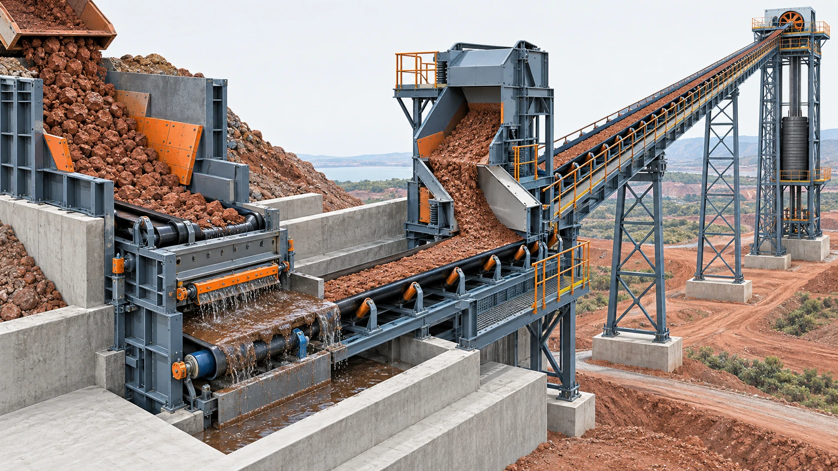 The same bauxite route can combine impact, wet cleanup and long-distance tension duties, so each flight needs its own input sheet.
Separate abrasion, adhesion, impact and distance
“Abrasive bauxite” is a useful warning, but it is not a complete specification. Four different mechanisms can act together, and each calls for a different response.
Abrasion is progressive cover loss caused by material sliding or rubbing against the belt. It is influenced by particle shape, fines, loading trajectory, chute liners and belt speed. Cover thickness and compound selection matter, but a thick cover does not correct a transfer that forces material to slide across the belt.
Adhesion and carryback occur when wet or fine material remains on the belt after discharge. This affects cleaner choice, pressure adjustment, return-idler contamination and housekeeping. It can also turn an otherwise stable line into a tracking problem when buildup becomes uneven. The material condition at the wettest realistic operating point matters more than a dry sample taken during a site walk.
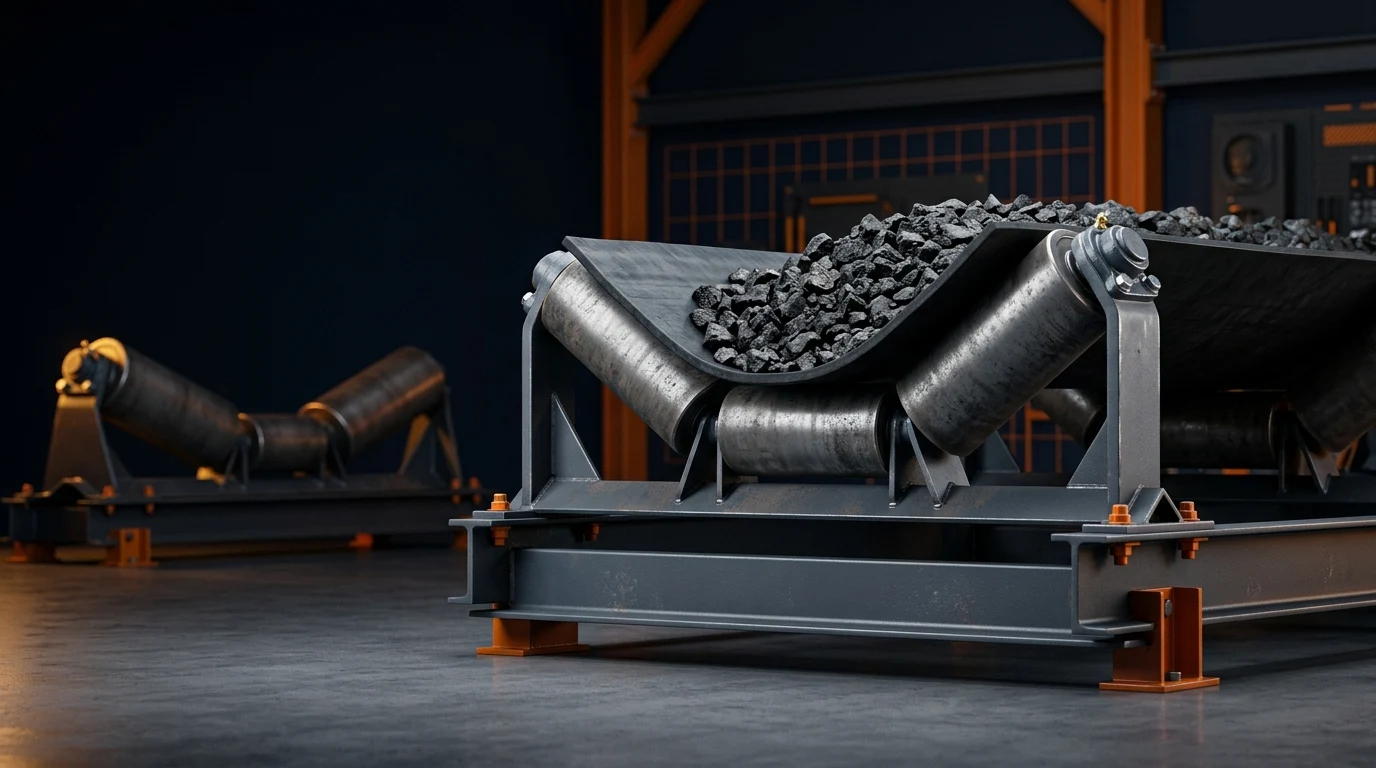
Impact is concentrated damage where a material stream lands on the receiving belt. It is driven by lump mass, vertical drop, material velocity, belt support and stream centring. The usual response is not simply “a stronger belt.” It is a combined review of chute trajectory, impact support, idler spacing, cover protection and accessible wear parts.
Distance and lift create tension and elongation requirements. They influence carcass choice, take-up travel, splice approach, pulley and drive arrangement, as well as starting and stopping behaviour. A long conveyor can have modest abrasion duty; a short crusher discharge can have severe impact duty. Neither condition can be inferred from the other.
Use this four-risk check at every zone. It keeps a project team from asking one feature—such as an abrasion-resistant cover or a high-strength carcass—to solve a problem that originates in loading, cleaning or route geometry.
| Risk to isolate | Evidence to collect | System response to evaluate |
|---|---|---|
| Abrasion | Cover loss pattern, particle shape, sliding distance and liner condition | Cover compound/thickness, loading trajectory and wear-liner access |
| Adhesion | Wettest operating condition, fines fraction, cleaner carryback and return buildup | Cleaner arrangement, dribble collection, return-idler protection and seal maintenance |
| Impact | Top size, lump mass, drop height and incoming material velocity | Chute trajectory, impact support, close idler spacing and cover protection |
| Distance and lift | Profile, effective tension, take-up travel and start/stop duty | Carcass construction, splice plan, pulley/drive arrangement and dynamic review |
Treat the table as a specification checklist, not a way to assign a universal belt grade. It makes the missing input visible before a supplier fills the gap with an assumption.
Choose carcass and covers in separate passes
After the route and risk sheet are complete, make two related but separate decisions.
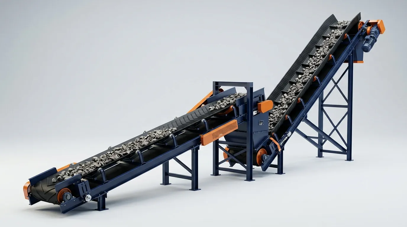
First, choose the carcass from the calculated tension and elongation requirements. For short to moderate flights, fabric conveyor belt construction may be suitable when its rated strength, elongation, splice arrangement and pulley compatibility all meet the calculated cases. For long, high-tension or high-lift flights, steel cord conveyor belt construction is commonly evaluated because low elongation can reduce the take-up challenge. That decision brings its own requirements for splice quality, inspection, damage monitoring and installation planning.
The principle is important: carcass selection answers whether the belt can transmit the required forces over its intended life. It does not answer whether the material interface will destroy the cover.
Then specify the top and bottom covers from the material and interface. Record the likely abrasion pattern, sharp or hard inclusions, moisture, fines, temperature, cleaner contact, chute-liner condition and any exposure that can affect the rubber. Cover thickness should be linked to the actual loading and wear zones, not copied from a nearby conveyor with a different material stream.
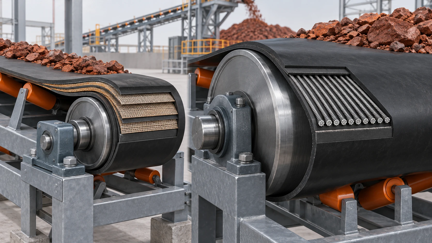 Carcass and cover are separate decisions: construction carries the calculated forces, while cover selection must survive the material interface.
Ask a supplier to state the assumptions behind both decisions. A meaningful proposal identifies its operating tension basis, safety margin, cover construction, splice scope, pulley limits and exclusions. A proposal that offers only a belt width and a generic “mining grade” does not give the buyer a comparable engineering basis.
Engineer bauxite transfers for belt life and cleanup
Many belt-life problems begin at a transfer point, not on the overland flight. A bauxite operation in northern Australia described by H & B Mining illustrates a common mechanism: a compromised belt line under the primary skirting contributed to spillage and belt wear. It is one supplier’s project account, not a universal performance claim, but its failure mode is broadly useful.
At every transfer, the receiving belt should see a centred material stream with a controlled direction and speed. When material arrives off-centre, too fast, or at a steep mismatch to belt travel, it can cut the cover, push material into the seal and initiate mistracking. When the belt sags in the skirted zone, an otherwise well-designed seal cannot stay consistent.
Review transfers in this order:
- Establish the actual discharge trajectory from the upstream belt speed, pulley and material condition.
- Shape the chute to guide the stream in the receiving belt’s travel direction instead of relying on the belt to accelerate it by friction.
- Set impact support and support spacing for the expected lump and loading case; make wear parts and rollers accessible.
- Allow settling length before the skirt seal ends, and preserve belt-edge clearance for sealing and tracking.
- Design cleaning and dribble collection around the wettest, most adhesive material condition—not around an ideal dry day.
Maintainability belongs in this design review. The transfer-design guidance from H & B Mining emphasizes that accessible rollers, skirt liners and sealing components help maintain a consistent belt line. Even where different equipment is used, the engineering point stands: a seal that cannot be inspected and adjusted will not remain a seal for long.
For a deeper treatment of trajectory, impact and containment inputs, use the belt conveyor transfer-chute design guide alongside the flight-specific data sheet.
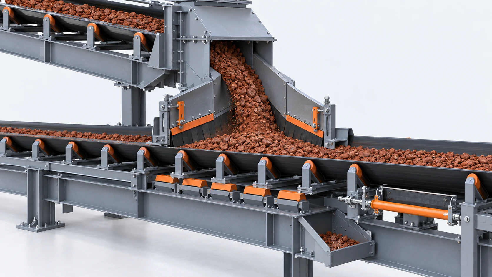 A transfer point must control the material stream, support the receiving belt and remain accessible for inspection and cleanup.
Turn the route into capacity, tension and power cases
Once every flight has a material and route description, calculate from capacity through to belt construction and drive duty. Do not start with motor power alone.
- Set the capacity cases. Define normal, design and peak throughput; bulk density; belt width; speed; surcharge assumption; and the actual loading profile. If a stockpile or surge bin feeds the line, model the peak condition rather than assuming a smooth average.
- Build the resistance and tension cases. Include lift, length, rolling resistance, curves, skirt friction, cleaners, ploughs and special equipment. Check running, starting, stopping and adverse loading conditions. The critical case is not always steady operation on a level line.
- Confirm take-up and splice requirements. Take-up travel must accommodate the selected carcass, installation conditions and tension variation. The splice is part of the conveyor duty, not a detail to decide after the belt is ordered.
- Size the drive and controls. Match motor, reducer, pulley, braking and control philosophy to the actual route. High lift, long downhill sections or demanding restart conditions require a dedicated dynamic review; a preliminary power number is only a starting point.
For early design, BisonConvey’s belt tension calculator and conveyor motor power calculator can make the input assumptions visible and help a team identify missing data. They cannot validate every transient, structural, pulley, splice and chute detail for a mine-specific installation. The final selection must be checked against the project’s governing method, installed equipment limits and the selected supplier’s data.
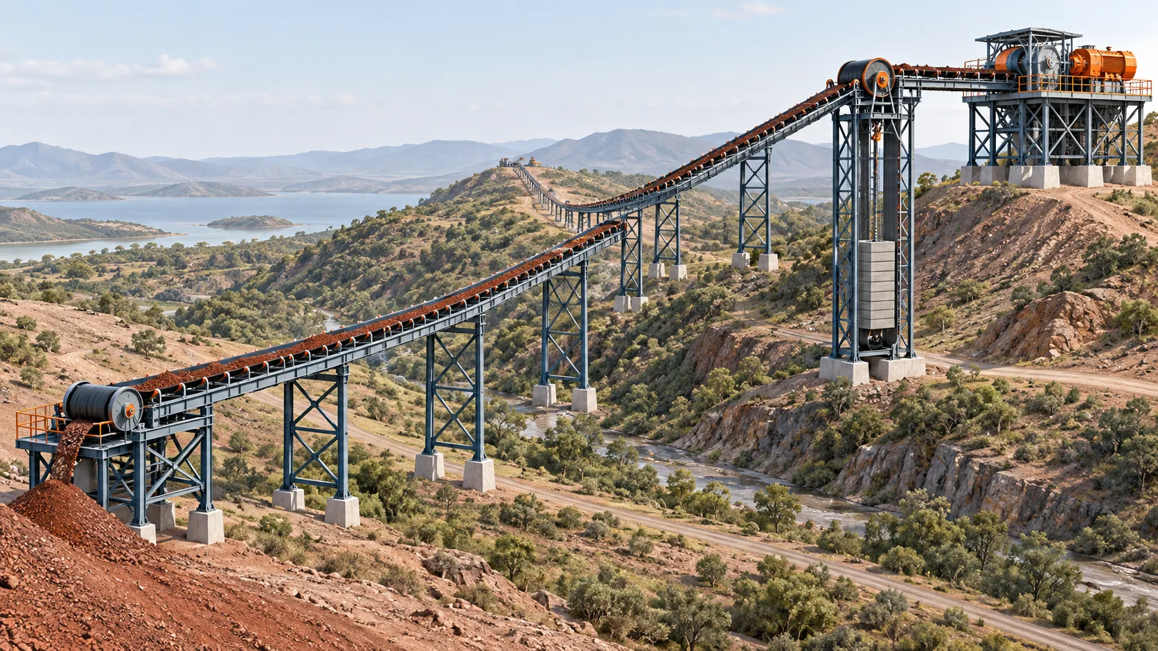 On a long route, lift, effective tension, drive arrangement and take-up travel must be evaluated as one system.
Issue an RFQ suppliers can compare
An RFQ that asks only for a “bauxite conveyor belt, 1,200 mm wide” leaves too much room for incompatible assumptions. Issue a brief for each flight that includes the following fields.
| RFQ block | What a supplier needs to evaluate it consistently |
|---|---|
| Process and material | Conveyor purpose/location; bulk-density range; top size; fines fraction; moisture range |
| Capacity and route | Normal, design and surge throughput; centre distance; lift; profile; target speed and width |
| Belt construction | Calculated tension cases; take-up arrangement; requested carcass evaluation; cover requirements |
| Transfer and maintenance | Loading, impact support, sealing, cleaning, dribble collection, access and shutdown window |
| Scope and acceptance | Governing standards, test documents, splice scope, exclusions and acceptance requirements |
Ask every supplier to identify exceptions and assumptions against the same data sheet. That makes it possible to see whether a price difference comes from cover construction, carcass rating, splice scope, an omitted take-up requirement or an unaddressed transfer problem.
The practical next step is simple: draw the real bauxite route, create a zone sheet for every conveyor flight, and rate each one for abrasion, adhesion, impact and distance before requesting a belt type. That order produces a more comparable RFQ—and prevents a generic mining belt from becoming the expensive answer to the wrong problem.