A port conveyor belt is not selected by asking whether the terminal handles “bulk cargo.” The right selection begins with the material’s route: where it enters the terminal, how it is stored or reclaimed, how many transfers it crosses, and whether the line feeds a ship loader or receives from an unloader. Coal, iron ore and grain can all pass through the same quay, but they create different loading, cleanup and availability requirements.
That distinction matters at procurement. A request for a “bulk terminal conveyor” can describe anything from a short truck-receival belt to a long stockyard-to-berth route with a moving ship loader. If those duties are combined into one generic belt requirement, the quoted options will look comparable while being based on different assumptions. A better brief defines the duty of each conveyor flight first, then evaluates the belt construction, covers, transfers and drive inputs that support it.
Start with cargo flow, not a port conveyor belt label
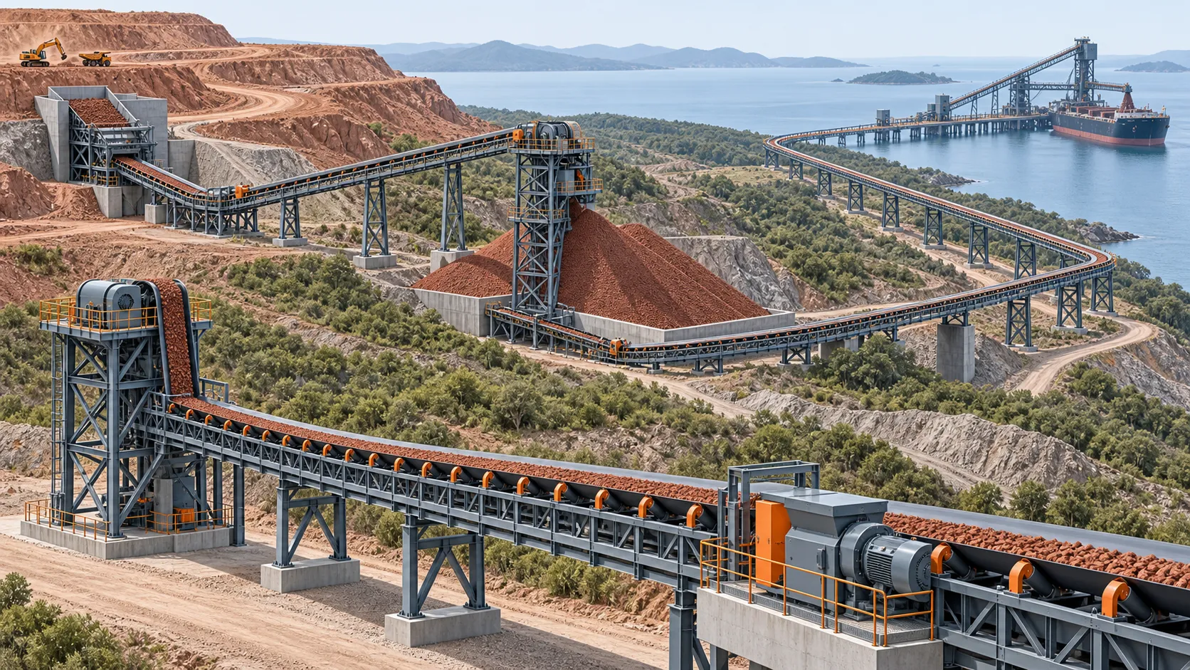
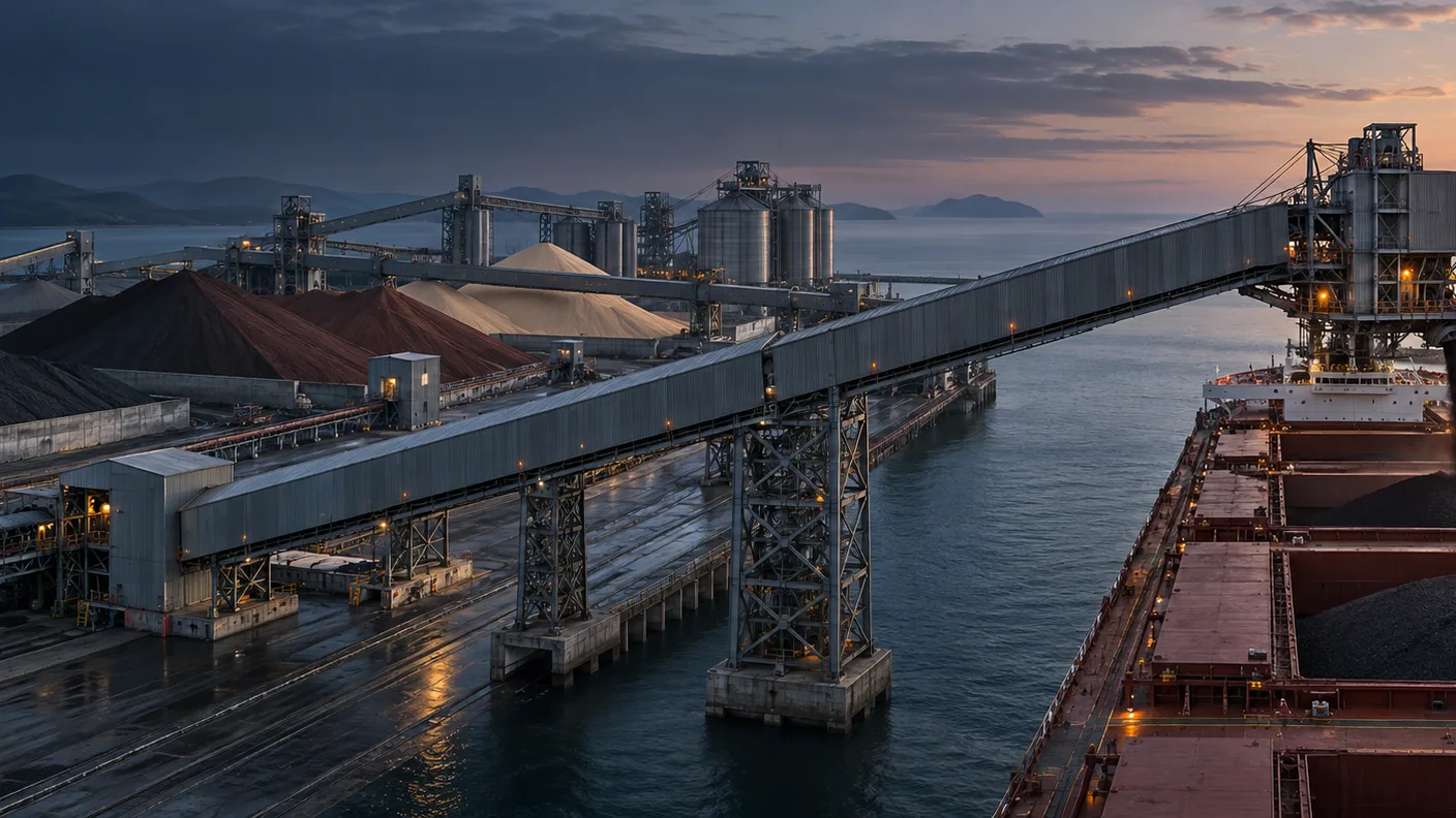
At an export terminal, material normally enters from rail, truck, pipeline, plant or an upstream conveyor; it may be screened, sampled, stacked and reclaimed before travelling to the berth. The final route commonly feeds a ship loading conveyor and a chute or boom that distributes material into the hold. At an import terminal, the direction reverses: an unloading machine, hopper or feeder supplies the first land-side belt, then material moves to a stockyard, processing plant or rail loadout.
The direction changes the design questions. A ship-loading route has to keep the ship-loader feed stable while stockyard reclaim and berth movement change. An unloading route may be dominated by the receiving hopper, impact at the first transfer and how reliably the system can handle intermittent discharge from the vessel interface. Neither case is well described by a single annual-tonnage figure.
The equipment list is also wider than the belt. A port bulk-loading system overview from SKE identifies the familiar chain of conveyors, stacker-reclaimers, ship loaders or unloaders, hoppers and storage equipment. The useful takeaway is not that every terminal needs every machine; it is that the belt must be specified in the context of the interfaces around it.
Before selecting a belt, record these facts for every flight:
- Its upstream and downstream equipment, including the direction of material flow.
- Normal, design and surge mass flow—not only the annual cargo volume.
- Bulk density range, top size, fines content and realistic moisture condition at that point in the route.
- Centre distance, lift, curves, belt speed, loading geometry and take-up arrangement.
- The consequence of an interruption: whether the terminal has storage, a bypass path or a vessel-operation constraint.
This separates a port-wide logistics diagram from an engineering input sheet. It also reveals where a common terminal name hides several different conveyor duties.
Map the terminal into conveyor zones
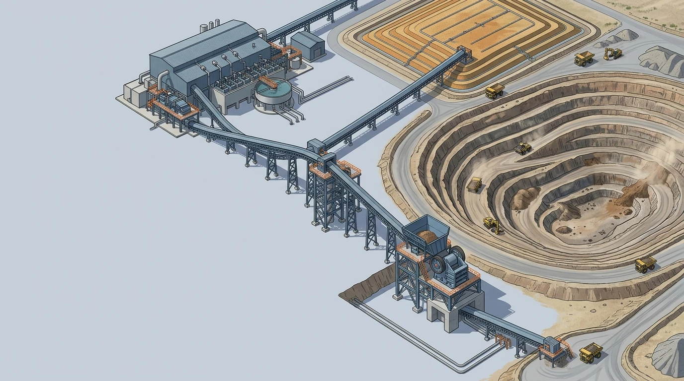
The simplest way to avoid a generic specification is to divide the material path into zones and create one short duty record for each conveyor. The same commodity can be gentle to convey in one zone and destructive in the next.
| Conveyor zone | Typical duty | What changes the selection | Inputs to confirm |
|---|---|---|---|
| Receiving and feed | Rail, truck, hopper or upstream process discharges onto the first belt | Impact, surging, off-centre loading and fines generation | Top size, lump mass, drop height, feed rate and loading trajectory |
| Yard transfer and stacking | Material moves to a stockpile or storage shed | Distance, weather exposure, dust containment and transfer wear | Route profile, exposure, belt speed, transfer layout and operating hours |
| Reclaim and blending | Reclaimed material feeds a plant or berth route | Variable flow, moisture, carryback and product segregation | Reclaim rate, moisture range, blend rules and cleaner access |
| Berth approach | Material moves from yard to the quay | Sustained tension, availability and access constraints | Centre distance, lift, take-up, drive arrangement and maintenance window |
| Ship interface | A travelling or luffing machine feeds or receives from the vessel | Movement, transfer control, trimming pattern and spillage sensitivity | Machine travel, boom geometry, receiving-belt direction and chute arrangement |
| Return and cleanup | The belt returns through cleaners, ploughs and collection points | Carryback, buildup, tracking and access for service | Wettest material condition, cleaner plan, drainage and inspection access |
The zone map should follow the physical conveyor flights rather than department boundaries. A stacker feed belt and a berth belt may both be called “yard conveyors,” yet one might be short and impact-heavy while the other is long, tension-led and difficult to access during vessel operations.
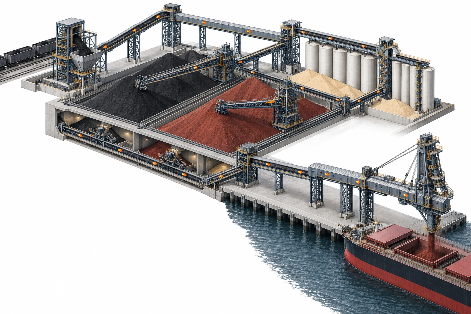 A terminal route should be separated into conveyor flights, because each zone can have a different loading, wear and maintenance duty.
For grain, the receiving end often deserves early attention. MLT Group’s port example describes grain terminals using unloading pits to take cereals from arriving transport through to ship loading. That is a useful reminder that rapid receipt, controlled routing and containment belong in the process description before a grain terminal conveyor is priced.
Treat coal, iron ore and grain as different duties
Commodity names are helpful starting points, but they are not belt specifications. The material condition, transfer design and operating environment determine what the belt actually sees.
Coal: control fines, moisture and cleanup
Coal routes frequently require close attention to dust, fines and cleanup. A dry transfer may make containment and dust-management interfaces prominent; a wet or fine material stream can increase adhesion and carryback. The engineering response is not just a cover choice. It includes loading alignment, skirt-seal support, cleaner arrangement, dribble collection and access to inspect those components.
If a coal terminal has multiple sources or blending duties, record the worst credible feed condition for each flight. A belt that runs cleanly with one source can behave differently after a change in fines fraction or moisture. Site-specific dust, fire and electrical requirements should be reviewed against the governing terminal rules rather than inferred from the cargo label alone.
Iron ore: isolate impact and abrasive wear
Iron ore duties often expose the receiving belt to heavy, hard or sharp material. The main failure mechanism may be impact at a chute, sliding abrasion in a poorly matched transfer, or sustained cover wear on a long route. Those mechanisms are related, but a high-strength carcass does not correct an aggressive loading trajectory, and a thicker cover does not solve inadequate impact support.
At an ore transfer, capture the actual top size, maximum lump condition, vertical drop, incoming velocity, chute-liner condition and the centring of the stream. Then evaluate the belt, support arrangement and chute as one receiving system. This gives suppliers a basis to state what their proposal addresses rather than applying a generic “ore grade” label.
Grain: protect product quality and keep the route clean
Grain is usually less abrasive than ore, but a grain terminal conveyor can still have demanding requirements. Breakage, contamination, residue between cargoes, spillage and access for cleaning may be more important than heavy-duty impact resistance. Gentle transfer geometry and a route that can be cleaned and inspected are therefore part of the selection discussion.
The intended commodity also matters. A terminal handling one grain product in a dedicated line has a different cleaning and segregation problem from a multi-cargo operation. If food-contact, sanitation or local handling rules apply, list them in the RFQ and ask each supplier to confirm the scope it can support. Do not assume that a belt suitable for dry bulk service automatically meets a terminal’s product-handling requirements.
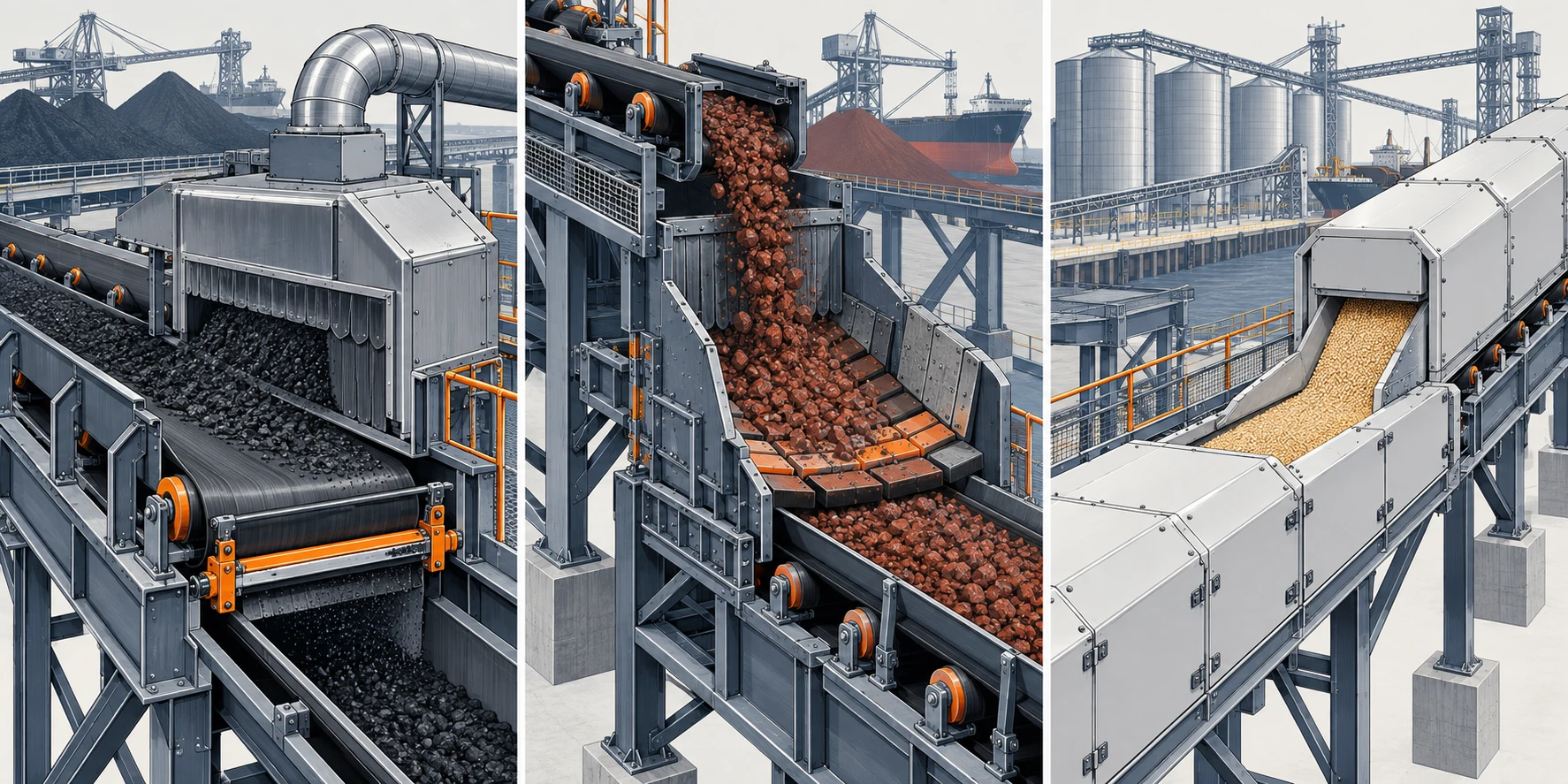 Coal, iron ore and grain create different transfer, cleaning and material-protection priorities even within the same terminal.
Select carcass and covers in separate passes
Once the route is clear, make two connected decisions instead of choosing a single “port belt grade.”
First, select the carcass from calculated force and elongation requirements. Centre distance, lift, effective tension, take-up travel, pulley arrangement, splice method and start-stop duty establish whether a proposed construction is appropriate. Long or high-tension flights may lead a project team to evaluate a steel-cord conveyor belt construction; shorter routes may be suitable for fabric conveyor belt construction if the calculated cases, splice plan and pulley limits are satisfied. The route—not the presence of a berth—should drive that evaluation.
Second, select the covers from the material interface. Record where the belt is struck, where material slides, the likely abrasive pattern, moisture and fines, cleaner contact, ambient exposure and any temperature or chemical conditions that are actually present. A cover is a wear surface, but it is also part of a system that includes the chute, liners, impact support and cleaners.
Ask suppliers to make their assumptions visible. A comparable proposal should say which capacity and tension case it uses, what carcass and cover construction it offers, where the splice responsibility sits, which pulley limits apply and what it excludes. A price attached only to width and length cannot show whether two bids solve the same duty.
Engineer transfers, weather exposure and maintenance access together
Ports add outdoor exposure and difficult operating windows to ordinary bulk conveying. Rain, wind, salt-laden air, changing material moisture and limited berth access can influence the design of covers, guards, drainage, corrosion protection, enclosures and cleanup systems. These details need a project-specific review; they are not a universal port-conveyor specification.
The transfer is usually the place to begin. A receiving belt should be loaded as close as practical to its direction and speed, with the stream centred and allowed to settle before the skirted zone ends. When material is forced to accelerate by friction against the belt, it can increase cover wear and move towards a skirt seal. When the belt line is poorly supported, sealing and tracking become harder to keep stable.
Use a transfer review that answers five practical questions:
- Does the chute guide material in the receiving belt’s travel direction?
- Are top size, lump mass and drop height matched to the impact-support and idler-spacing concept?
- Can the crew reach liners, rollers, seals and cleaners without an impractical shutdown or unsafe access arrangement?
- Where will carryback, washdown water or spillage collect, and how will it be removed?
- What changes when the material arrives at its wettest credible condition or when the berth line is operating continuously?
This is also where the boundary between belt supply and terminal equipment needs to be explicit. A belt supplier can specify a belt and its operating limits, but terminal reliability depends on the full loading, support, cleaning and maintenance arrangement.
For a deeper review of trajectory, impact and containment inputs, use the belt conveyor transfer-chute design guide alongside the flight-specific duty record.
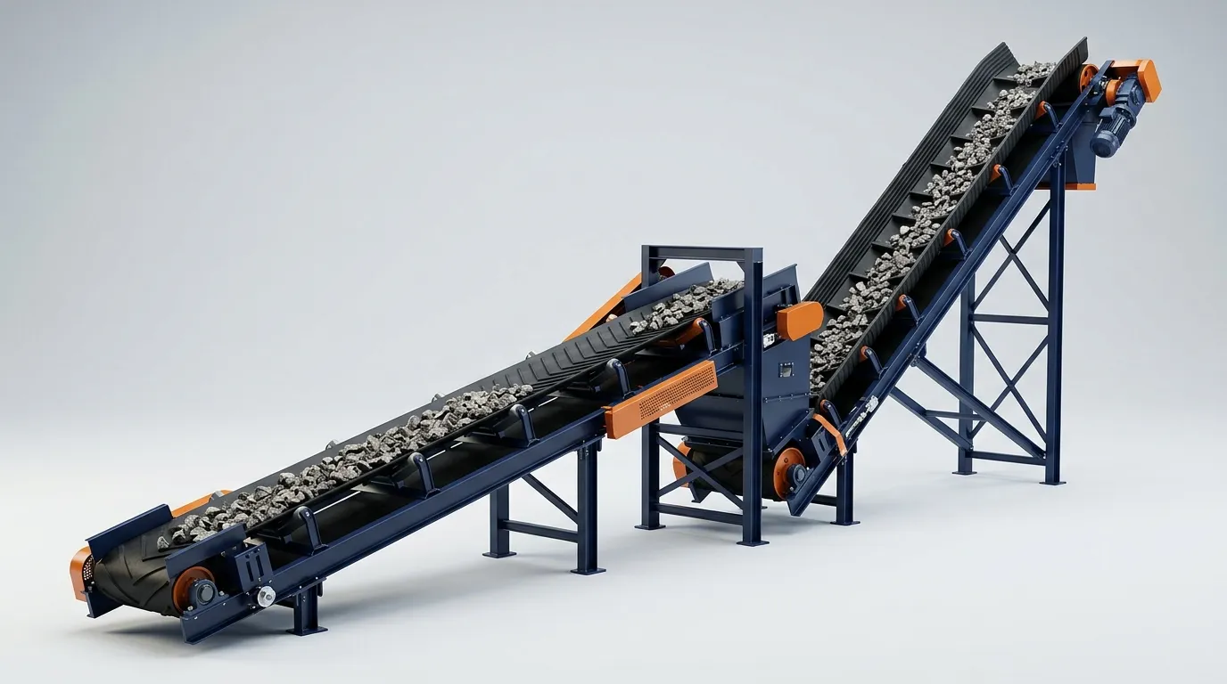
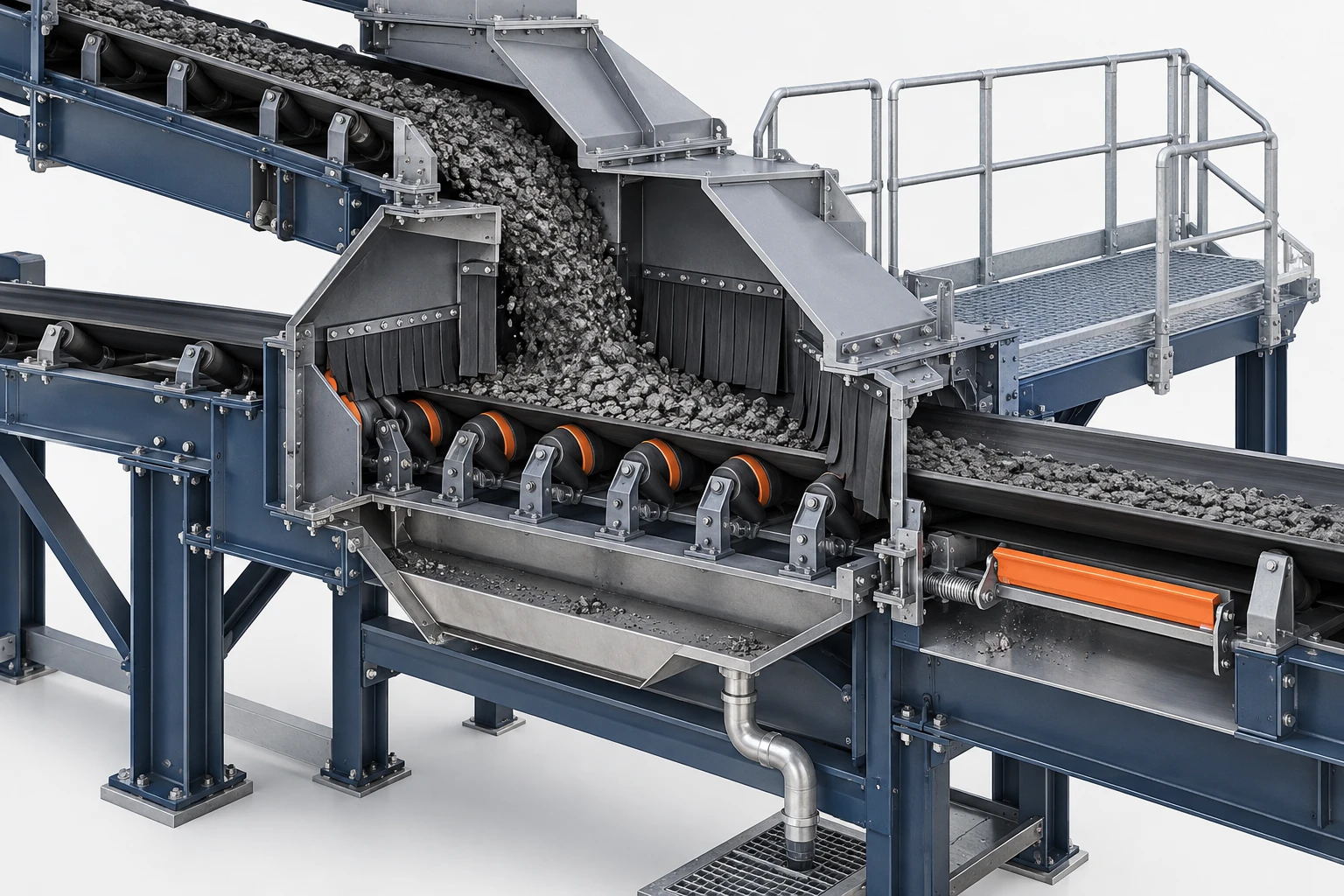 A transfer point must control the material stream, support the receiving belt and remain accessible for inspection and cleanup.
Turn the route into capacity, tension and drive cases
Capacity is a starting input, not a final selection. A defensible design sequence moves from process duty to running resistance and then to belt construction and drive requirements.
- Set capacity cases. Define normal, design and surge throughput; bulk-density range; loading profile; belt width; speed; and the surcharge assumptions used. Reclaim or ship-loader feed can create a peak case that an average daily tonnage will not reveal.
- Build resistance and tension cases. Include route length, lift, idler resistance, curves, loading friction, skirt resistance, cleaners, ploughs and special equipment. Review running, starting, stopping and adverse loading conditions.
- Confirm take-up and splice scope. Take-up travel must suit the selected belt and the variation expected through installation and operation. The splice must be considered as part of the conveyor duty, not as a late purchasing detail.
- Size the drive and controls. Motor, gearbox, pulley, braking and control choices follow the actual route and operating cases. Long downhill routes, high lift or demanding restart conditions need a dedicated project-level assessment.
For early design, the conveyor belt capacity calculator can make the capacity assumptions visible before a width or speed is treated as fixed. Use the belt tension calculator and conveyor motor power calculator as transparent preliminary checks after the route inputs are defined. They do not replace project-specific reviews of transients, structures, pulleys, splices and transfer equipment.
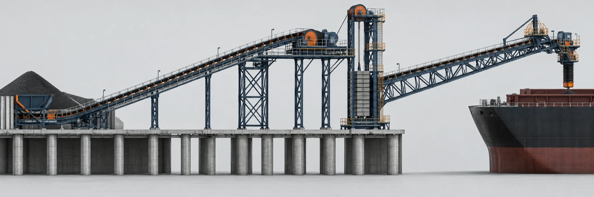 Capacity, route profile, drive arrangement and take-up travel must be evaluated as one conveyor system.
This sequence prevents a preliminary motor number from being treated as a complete belt design. It also gives the design team a clear list of unknowns before it asks a manufacturer to fill them with assumptions.
Issue an RFQ that makes bids comparable
The practical output of the selection process is one data sheet per conveyor flight. It should allow every bidder to quote against the same process duty and make exceptions visible.
| RFQ block | Information to provide |
|---|---|
| Process and material | Conveyor role, commodity, bulk-density range, top size, fines content, moisture range and any segregation requirement |
| Capacity and route | Normal, design and surge rate; centre distance; lift; profile; target speed; width; curves and transfer locations |
| Belt evaluation | Calculated tension cases, take-up arrangement, pulley constraints, proposed carcass review, cover wear conditions and splice scope |
| Terminal environment | Outdoor exposure, drainage and cleanup concept, corrosion-protection requirements, enclosure needs and maintenance-access limits |
| Interfaces and acceptance | Upstream/downstream equipment, loading geometry, applicable project requirements, test documentation, exclusions and acceptance criteria |
Ask bidders to return their assumptions against the same table. The differences then become useful: a higher price may reflect a different cover construction, a more demanding splice scope, an allowance for take-up, or a limitation that needs to be solved at a transfer point. That is far more valuable than comparing a list of belt widths and nominal strengths.
For the next project review, draw the actual cargo route from receipt to ship or ship to storage, divide it into conveyor flights, and complete the data sheet before deciding on a belt construction. That order turns a broad port-conveyor request into a selection brief that engineering, operations and procurement can all evaluate.