Shaft Alignment Options for Conveyor Drives — Ultimate Guide
When conveyor drives go out of alignment, the costs show up everywhere: bearing heat, coupling damage, vibration, energy loss, and unplanned downtime. This guide explains Shaft Alignment Options for Conveyor Drives—what configurations exist, how they influence alignment work, and how to measure, correct, and maintain alignment using standards-aligned practices.
Written for plant engineers, maintenance/reliability teams, and procurement managers, it blends field workflow with authoritative guidance so you can choose the right option and get it aligned the right way.
Key takeaways
-
Alignment is about making shaft centerlines colinear within acceptable tolerances; flexible couplings help but do not replace precision.
-
Drive configuration affects alignment tasks: base-mounted gearboxes require precision coupling alignment; shaft-mounted reducers simplify points of alignment but have application limits; belt drives focus on sheave alignment.
-
Use OEM tolerances first. When absent, apply speed-based tolerance concepts from recognized standards and expert sources.
-
Laser tools speed measurement and reduce math errors; dial-indicator methods remain effective in skilled hands and tight spaces.
-
Control installation preconditions—base flatness, soft foot, runout, pipe strain—before precision alignment.
-
Account for thermal growth (cold-to-hot movement) so the running condition lands in spec.
-
Always follow LOTO and guarding rules; plan acceptance checks and documentation.
Core concepts and vocabulary
Shaft alignment means adjusting connected machines so their rotational centerlines match. Two primary misalignment types matter:
-
Offset (parallel) misalignment: lateral separation of centerlines.
-
Angular misalignment: the centerlines intersect at an angle (commonly expressed in mils per inch or mm/m).
Terms you’ll use in the field:
-
Soft foot: one or more feet do not sit flat or coplanar, distorting the frame when tightened and corrupting readings.
-
Runout: eccentricity or wobble of shafts/hubs that must be checked before alignment.
-
OLTR/thermal growth: the difference between cold setup and hot running position—set targets so operation lands inside tolerance.
Standards and industry guidance underpinning good practice:
-
The Electric Apparatus Service Association summarizes the adoption and scope of the ANSI/ASA S2.75 shaft alignment standard, including terminology and tolerance concepts. See the industry overview in the EASA note on the new standard: overview of ANSI/ASA S2.75 adoption by EASA (2017).
-
Installation and alignment best practices (base preparation, soft foot elimination, pipe strain control, target alignment) are well captured in API 686–aligned field practices summarized by LUDECA: installation and alignment best-practice notes reflecting API 686.
Conveyor drive configurations and alignment implications
Conveyor drives are typically arranged in one of these ways. Each choice changes what you must align and how precise you must be.
-
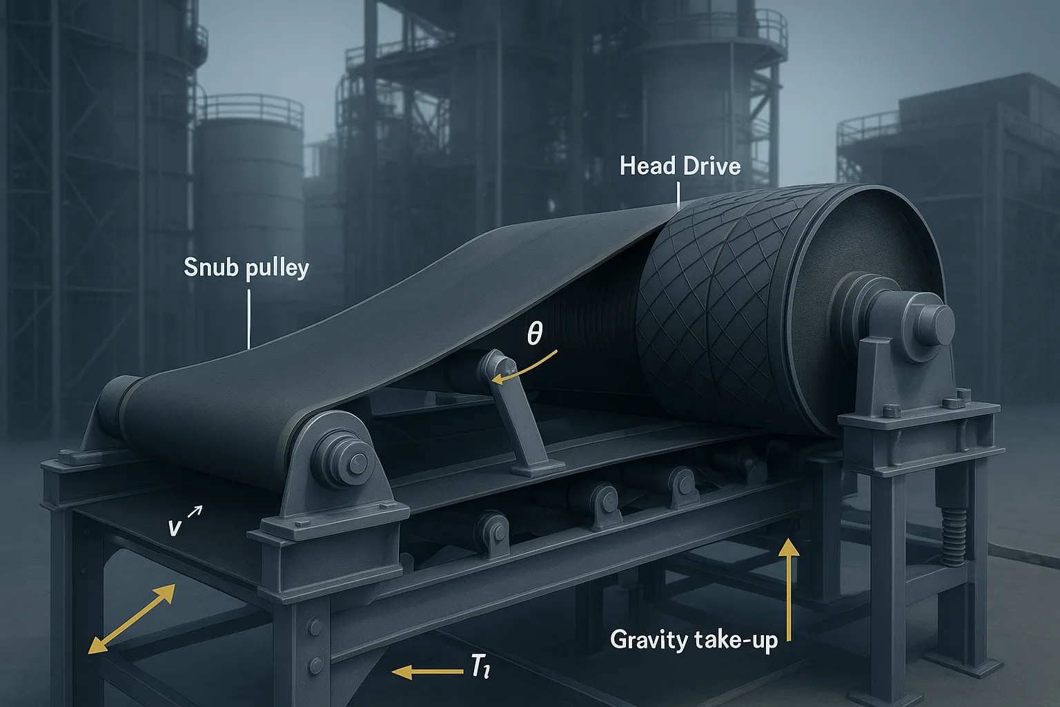
Base-mounted gearbox + flexible coupling: A motor drives a base-mounted reducer, which couples to the pulley or intermediary shaft. You must align motor-to-gearbox and gearbox-to-driven shaft within coupling and OEM limits. Strong for high power and modular maintenance, but more alignment steps.
-
Shaft-mounted reducer (alignment-free concept): The reducer mounts on the pulley shaft; alignment between motor and reducer may be set by a mounting kit. Field work shifts to verifying torque-arm geometry and ensuring the reducer sits square on the pulley shaft. Practical power limits and lifting/maintenance constraints apply.
-
Belt-drive (sheaves) vs direct-coupled: Belt drives require precise sheave alignment (offset and angular); direct-coupled drives remove sheaves but demand tighter shaft/coupling tolerances.
Context and deeper reading from established conveyor OEMs is helpful when selecting architectures. West River offers a practical overview of alignment implications across drive options: alignment options in conveyor drives and their implications. For broader drive selection context, see FEECO’s engineering guide: conveyor drive assembly selection considerations.
For procurement or design teams comparing shaft-mounted reducers specifically, see our engineering-focused guide: Selecting Shaft-Mount Reducers for Conveyors.
Drive option comparison
Note: Always verify OEM limits for torque, overhung loads, and allowable misalignment before finalizing a configuration.
Couplings and alignment behavior
Coupling choice influences what misalignment can be tolerated and how failures present:
-
Rigid couplings transmit torque with no misalignment capacity; alignment must be near-perfect.
-
Flexible couplings (elastomeric, grid, disc) allow limited angular, parallel, and sometimes axial movement. They reduce transmitted forces and protect equipment, but exceeding ratings accelerates wear.
For fundamentals, see U.S. Tsubaki’s overview of coupling behavior: rigid vs flexible coupling differences and implications.
Coupling comparison (behavioral overview)
Always confirm the specific coupling’s allowable misalignment from the OEM datasheet.
Measurement methods and field workflows
First, safety. Before any alignment work:
-
Follow your site’s written energy control program (LOTO). OSHA’s training material reiterates that lockout/tagout is the default for controlling hazardous energy; never defeat guards or expose personnel to rotating components: OSHA energy control (LOTO) program training manual.
-
Plan guard removal and alternative protection per procedure; re-install guards before returning to service.
Then, adopt a two-phase workflow: rough-in checks followed by precision alignment.
Rough-in checks (catch the big stuff):
-
Verify base/soleplate flatness and level; confirm shims are clean and full-contact.
-
Detect and correct soft foot before any precision reading.
-
Check shaft and hub runout; correct mechanical issues and replace damaged elements.
-
Isolate pipe/conduit strain pulling on frames.
Dial-indicator methods (face-and-rim, reverse dial):
-
Mount indicators appropriately; record readings at clocked positions (e.g., 0°, 90°, 180°, 270°).
-
Use machine geometry (span and foot distances) to calculate angular and offset misalignment.
-
Translate calculated values to foot moves (shim changes and lateral moves). Re-measure and iterate until within tolerance.
-
Oasis provides a clear method overview contrasting mechanical vs laser approaches: how to align machines — method fundamentals and workflow.
Laser alignment workflow:
-
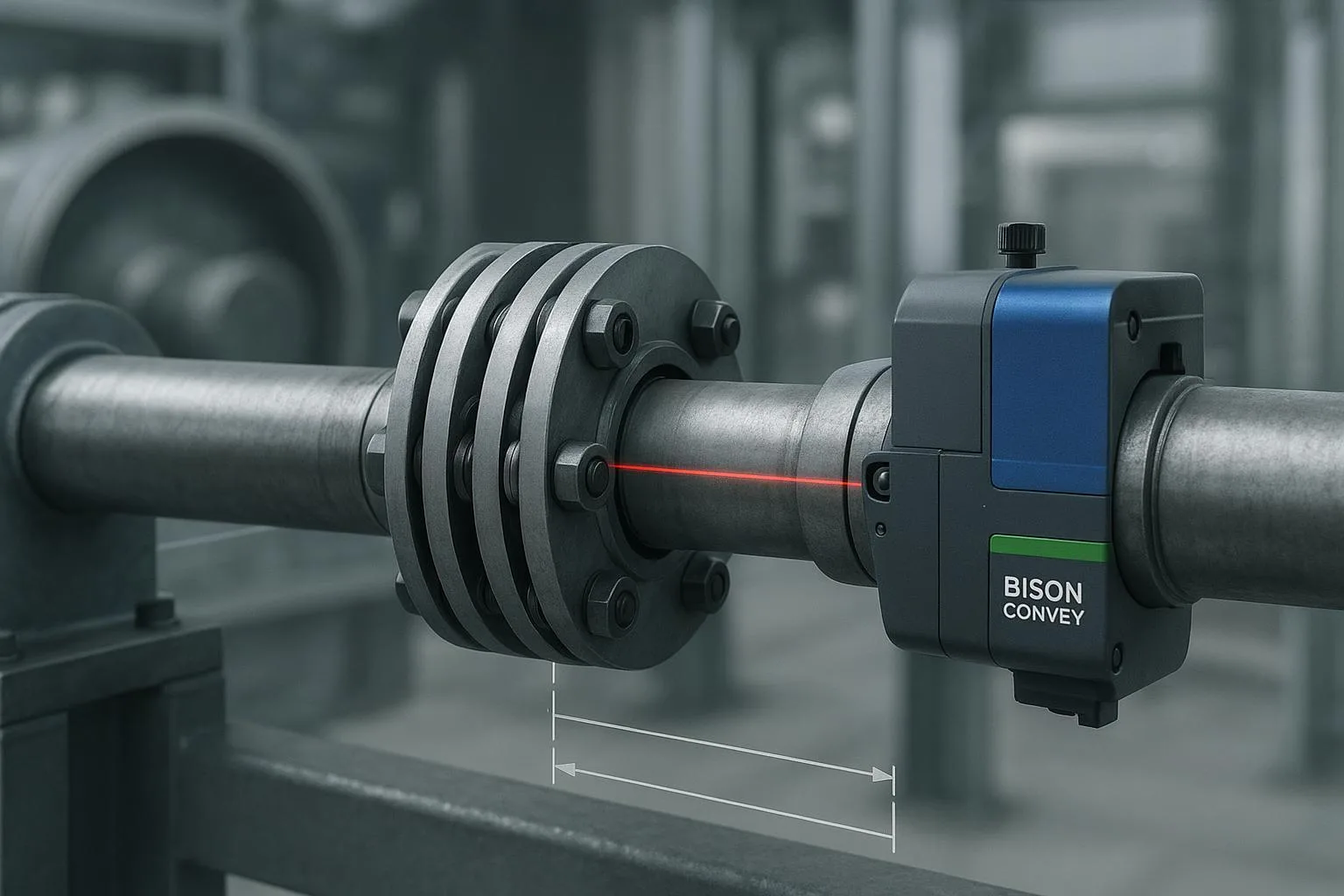
Enter span and foot geometry; mount the laser/sensor heads on both shafts or hubs.
-
Rotate through measurement positions; let the system compute vertical and horizontal corrections.
-
Perform moves, tighten to torque, and verify; use the software’s acceptance criteria and documentation features.
-
Laser tools reduce math errors and speed documentation, especially useful for complex multi-machine trains.
Cold vs hot alignment (OLTR targets):
-
Machines shift as they heat; set “cold” targets so that at operating temperature you land inside tolerance.
-
When OEMs provide target offsets, use them. Where not, industry guides explain how thermal expansion affects alignment and why to document target values: thermal expansion’s impact on shaft alignment and target setting.
Tolerances and acceptance
-
OEM-first: Always apply coupling and gearbox/motor manufacturer limits ahead of generic charts.
-
Standards and industry guidance: The ANSI/ASA S2.75 framework (as summarized by EASA) and expert resources like Fluke’s tolerance guide explain offset and angular concepts and how tolerances tighten with speed. See: Fluke’s overview of shaft alignment tolerance concepts and speed effects.
-
Documentation: Record as-found and as-left values, geometry inputs, shim changes, bolt torques, and acceptance criteria. Keep signed records for reliability programs.
Illustrative quick reference (conceptual, not a substitute for OEM limits):
Installation prerequisites and corrections
Most “impossible” alignments trace back to poor installation conditions. API 686–aligned practices (as summarized by LUDECA) emphasize:
-
Base preparation: flatness, level, grout integrity; correct bolt-length and hole clearances.
-
Soft foot elimination: quantify type (parallel, angular, squishy) and correct with proper shimming or machining; re-verify after tightening.
-
Runout checks: measure shaft and hub runout; replace bent shafts or out-of-tolerance hubs.
-
Pipe and conduit strain: decouple external forces before final alignment.
-
Shimming practice: use clean, full-size shims; avoid stacks of thin shims that collapse over time; record changes.
If you are rebuilding or commissioning a conveyor and need a refresher on structure squareness and pulley setup, see our installation fundamentals guide: Conveyor Belt Installation — Ultimate Guide. For how drive and tail pulley alignment affects belt tracking, see: Conveyor Belt Alignment — Ultimate Guide.
For belt-drive arrangements, precision sheave alignment improves belt life and efficiency; modern laser sheave tools help control both angularity and offset, as discussed in PRUFTECHNIK’s coverage of precision sheave alignment for manufacturing efficiency: precision sheave alignment and why it matters.
Troubleshooting and maintenance
Common symptoms, probable causes, and corrective actions:
For belt tracking remediation beyond the drive, see our practical guide: How to fix conveyor belt misalignment (mistracking).
Preventive practices:
-
Periodically verify alignment during planned outages, especially after foundation work, component replacement, or significant temperature or load changes.
-
Keep a clean base and shim set; log all shim and move data.
-
Inspect couplings for wear, lubrication status (if applicable), and fastener torque.
How to Choose Among Shaft Alignment Options for Conveyor Drives
When deciding among Shaft Alignment Options for Conveyor Drives, consider:
-
Power and torque: Very high power often favors base-mounted gearboxes with robust couplings and foundations.
-
Access and maintainability: If you need modular service and individual component swaps, base-mounted can simplify lifts; compact layouts may favor shaft-mounted or direct-coupled.
-
Environment and contamination: Environments with dust or abrasive fines may influence coupling choice (e.g., sealed elastomeric vs lubricated grid).
-
Skill level and tools: Sites with laser systems and trained technicians can turn multi-point alignments quickly; others may prefer arrangements with fewer alignment points.
-
Total cost of ownership: Lower commissioning time for shaft-mounted arrangements can be attractive; factor in maintenance access and power limits.
A simple rule of thumb: pick the configuration that minimizes risk and complexity for your realities—then enforce OEM and standards-aligned alignment practice from day one.
Next steps
-
Confirm your current drive configuration and gather OEM alignment and coupling limits.
-
Plan a precision alignment during the next outage: correct soft foot, measure with laser or dial, document targets and acceptance.
-
If you are upgrading pulleys, idlers, or belts as part of a reliability improvement, a reputable supplier can help specify components that support accurate alignment and stable tracking. For example, BisonConvey can supply heavy-duty pulleys, idlers, and belts to support your corrective alignment projects and long-term reliability (Knowledge Base Source).
References (selected)
-
EASA summary of ANSI/ASA S2.75 shaft alignment standard adoption (2017) — terminology and tolerance concepts.
-
LUDECA alignment knowledge base — API 686–aligned installation and alignment practices (soft foot, thermal targets, pipe strain control).
-
Fluke shaft alignment tolerance guide — speed-based concepts, offset vs angular tolerances, documentation tips; and Fluke’s thermal expansion overview.
-
Oasis Alignment — method overview and practical workflow for dial vs laser approaches.
-
U.S. Tsubaki knowledge center — rigid vs flexible coupling fundamentals and misalignment capacity concepts.
-
PRUFTECHNIK blog — precision sheave alignment principles for belt drives and efficiency.
-
West River Conveyors — conveyor drive alignment options and implications for configuration choice.
-
FEECO International — conveyor drive assembly selection considerations.
-
OSHA training material — energy control (LOTO) program guidance for safe alignment work.