
Selecting Shaft Mount Reducers for Conveyors
Learn how to size and specify shaft‑mounted reducers for conveyors—torque, service factor, ratios, thermal capacity, backstops, and bushings. Get a practical checklist.
Title tag: Selecting Shaft Mount Reducers for Conveyors | Guide
Meta description: Learn how to size shaft‑mounted reducers for conveyors—torque, service factor, ratios, thermal capacity, backstops, and bushings.
Selecting Shaft Mount Reducers for Conveyors
When a conveyor won’t start smoothly, overheats its gearbox, or creeps backward on an incline, the root cause is often an incorrectly selected or installed shaft‑mounted reducer (SMR). This guide walks you through the engineering workflow—from load data to verifying mechanical and thermal ratings—so you can choose confidently and cut unplanned downtime.
According to industry practice, the reducer isn’t selected in isolation. Power demand depends on belt tensions, pulley diameter, idler condition, and ambient conditions. If you need a refresher on the surrounding hardware, see this broader context on the industrial conveyor belt systems.
Key takeaways
Correct SMR selection balances mechanical torque rating and thermal capacity; skipping the thermal check is a top cause of premature failures.
Service factor must reflect duty severity (starts/hour, shock, loading). Apply it before comparing to OEM torque ratings.
Backstops are required on inclined conveyors to prevent roll‑back; choose type and orientation per OEM guidance and safety rules.
Bushings, shaft fit, and torque‑arm setup are as critical as the gearbox size—most slips and fretting come from installation, not design.
Always verify overhung/radial load, sealing/lube class, and mounting orientation with the manufacturer’s tables.
Core concepts and plain‑language definitions
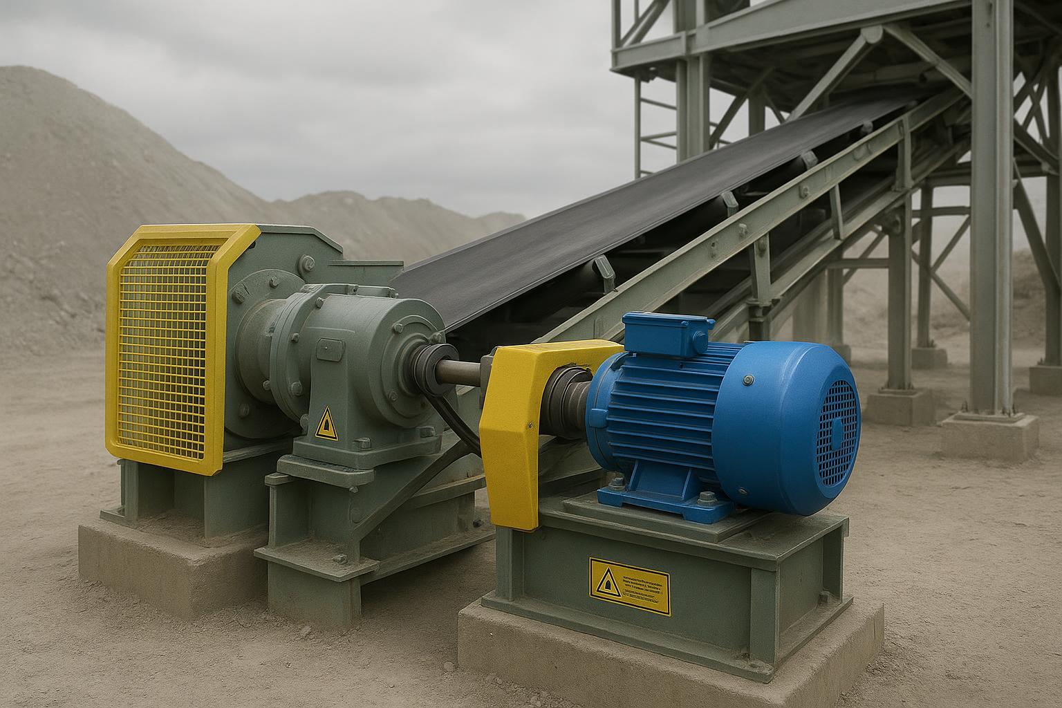
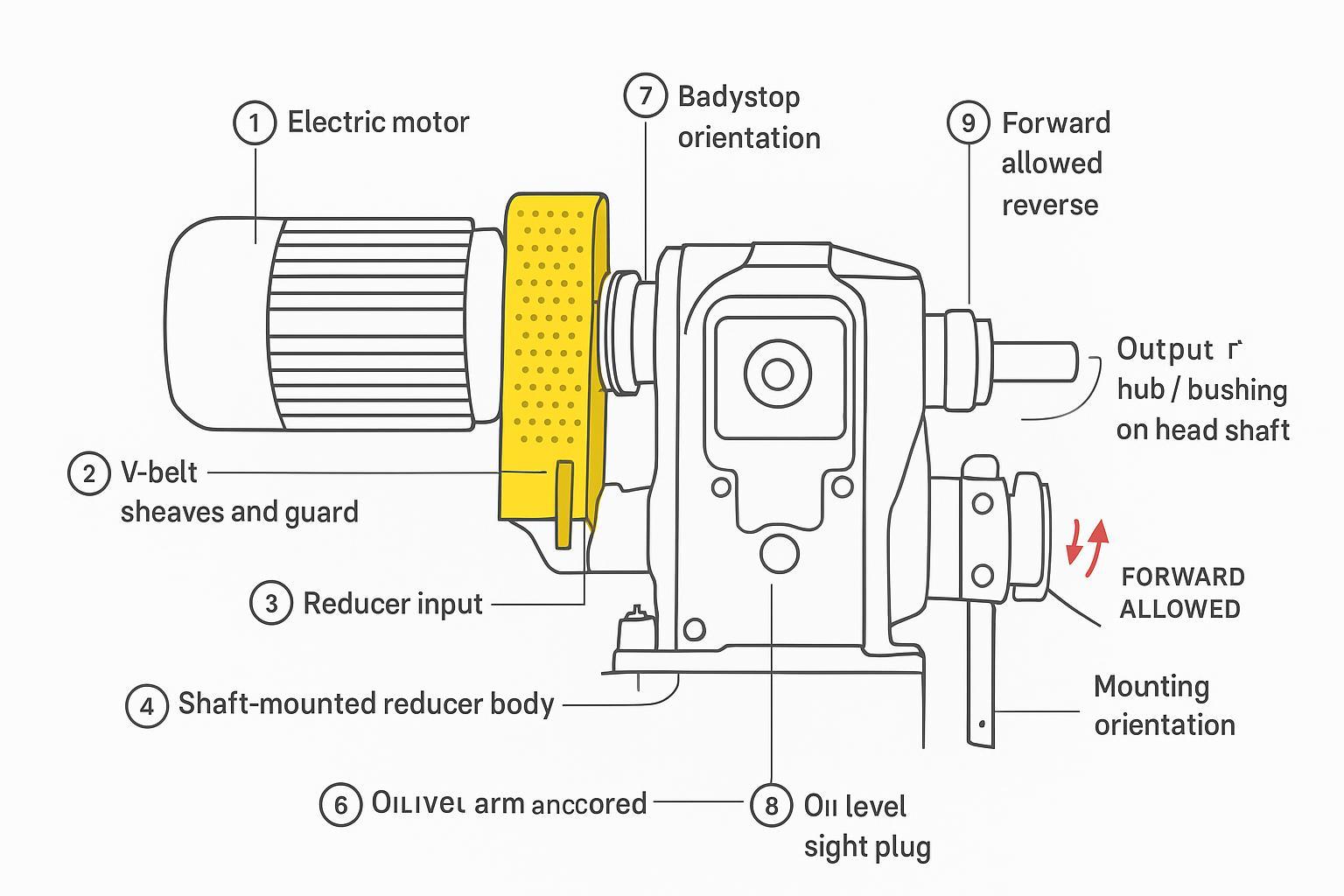
Shaft‑mounted reducer (SMR): A gearbox mounted directly to the conveyor head (or tail) pulley shaft. It’s restrained by a torque arm instead of a pedestal base and coupling. Benefits: fewer parts, compact footprint, and alignment simplicity. Trade‑offs: bushing fit and torque‑arm alignment become critical.
Ratio and belt speed: The reducer ratio slows the motor so the pulley turns at the target surface speed. Ratio choice links the motor rpm, pulley diameter, and belt speed. Too much ratio and the belt crawls; too little and the motor runs out of torque.
Output torque rating vs. required torque: The reducer’s rated output torque must exceed the required running torque multiplied by a service factor that covers shocks and duty severity.
Service factor (SF): A multiplier (e.g., 1.25–1.75) applied to running torque to account for starts, load variability, and shock. OEM catalogs define SF by application class; conveyors with frequent starts or high impact require higher SF. See OEM gearing catalogs such as the Dodge engineering catalog and Rexnord/Falk Quadrive guidance that emphasize choosing ratings with an appropriate service factor (2021–2025 era).
Thermal capacity: Even if mechanical torque fits, the gearbox can overheat if the thermal rating is exceeded—especially in hot ambients or continuous duty. SEW‑EURODRIVE manuals instruct checking “thermal gear unit load” and adding fans if needed; NORD highlights high cooling capacity in heavy‑duty conveyors (2022–2025 sources linked below).
Backstop/holdback: A one‑way clutch that allows forward rotation but prevents reverse runback. Common on inclined belts. OSHA requires anti‑rollback devices on inclined conveyor drive units. Formsprag guidance places holdbacks on the head shaft, opposite the drive, for typical layouts.
Bushing systems and shaft fit: SMRs use twin‑taper or single‑taper bushings, keyless locking, or screw‑conveyor adapters. Correct installation torque and shaft surface finish prevent fretting and slip.
Overhung/radial load (OHL): The pulley’s belt tensions apply radial load to the reducer’s output bearings. You must check allowable OHL for the selected frame, ratio, and mounting.
Mounting orientation, sealing, lubrication: Orientation codes change oil immersion and cooling; OEMs specify oil levels and venting. Seals and lube grade must match ambient temperature, dust, and duty.
Tip: Rolling resistance from idlers and misalignment inflates power demand. If idler drag is high, you’ll oversize the reducer. See why idlers matter in this explainer on belt conveyor idlers and their importance.
Practical applications and typical decisions
Inclined belt conveyors: Require backstops to prevent rollback; sizing must consider higher starting torque and braking dynamics.
Horizontal transfer conveyors: Often run continuously with modest starts/hour; thermal capacity can govern in hot plants with long duty cycles.
Screw conveyors: SMRs may use special adapters and seals to handle abrasive dust; bushing selection and sealing become primary.
Backstop choices and mounting snapshot
Use case | Typical mounting and notes | Evidence reference |
|---|---|---|
Inclined belt with risk of rollback | Backstop on head shaft; allows forward, prevents reverse; centrifugal lift‑off sprag types common in modern SMRs | OSHA 1926.800; Formsprag catalog; Dodge TAII brochure (lift‑off sprag) |
Horizontal belt, no rollback risk | Backstop typically not required; verify process safety case | Formsprag application notes |
Long downhill conveyor | May require braking and holdback strategy beyond gearbox backstop; consult system designer | Standards/practice vary; consult OEMs |
Modern TA‑style reducers note lift‑off sprag backstops compatible with EP oils, reducing wear during normal forward running, as stated in the Dodge Torque‑Arm II brochures.
Selecting Shaft Mount Reducers for Conveyors: step‑by‑step workflow
Gather application data
Conveyor type and layout (incline angle, length), belt width and speed, head pulley diameter, design tonnage, starts/hour, ambient temperature, duty cycle, expected dust/abrasives, and guarding constraints.
Calculate required running torque at the pulley
Determine required power (HP or kW) from belt tensions or from mass flow and friction estimates. CEMA practice bases drive selection on calculated power from belt tension analysis.
Convert to torque at the head shaft: T_out ≈ 63,025 × HP / rpm (imperial). Use the pulley rpm that meets target belt speed.
Apply service factor
Required selection torque = Running torque × SF. Choose SF per OEM tables for conveyors (light/medium/heavy shock; starts/hour). Rexnord/Falk and Dodge catalogs emphasize applying SF before comparing to ratings.
Choose ratio to meet belt speed
Ratio = motor rpm / pulley rpm. Check available reducer ratios and belt speed tolerance; adjust pulley diameter or sheave ratio if needed.
Bushing and shaft fit selection
Match reducer hub/bushing system to the pulley shaft diameter. Verify key/keyway or keyless design, installation torque, and shaft finish tolerance per the OEM manual.
Overhung/radial load check
Estimate radial load from belt tensions at the shaft and the geometry of the pulley. Compare to allowable OHL for the reducer frame/ratio/mounting orientation in the OEM tables. If data is not public (e.g., some Quadrive docs), consult the manufacturer.
Thermal capacity verification
Estimate thermal load from input power, duty cycle, ambient, and cooling conditions. Compare to the reducer’s thermal rating for the chosen orientation. SEW manuals instruct adding a fan or upsizing if thermal rating is exceeded; NORD literature emphasizes high cooling capacity options.
Mounting orientation, lubrication, and sealing
Confirm orientation code, oil fill volume, breather location, and seal type. Hot ambient or dusty service may require higher‑viscosity or special oils and heavy‑duty seals.
Backstop need and orientation
For any incline with rollback risk, include a backstop sized and oriented per OEM instructions. Formsprag guidance and OSHA rules support this requirement. Many TA‑style units use lift‑off sprag backstops compatible with EP oils.
Final specification and procurement checklist
Document selected frame size, ratio, output hub/bushing, keying/fit data, allowable OHL verification, thermal check outcome, backstop model/orientation, mounting position, oil type/volume, torque‑arm hardware, and guarding.
Quick selection checklist (printable)
Check | What to verify | Notes/source anchor |
|---|---|---|
Mechanical torque rating | Rated ≥ required torque × SF | Dodge/Rexnord catalogs stress SF-first selection |
Ratio and speed | Meets belt speed given pulley diameter | Standard conveyor calc; CEMA basis |
Thermal capacity | Thermal rating ≥ expected load/duty/ambient; add fan if needed | SEW manuals; NORD thermal notes |
OHL | Within allowable for frame/ratio/orientation | Consult OEM tables; contact app engineering if missing |
Backstop | Required on incline; type/orientation correct | OSHA; Formsprag; TAII notes |
Bushing/fit | Shaft diameter, keying, torque spec, surface finish | OEM bushing tables/manuals |
Orientation & lube | Oil level, breather, seal class, ambient | SEW/NORD/OEM instructions |
Torque arm | Alignment, neutral plane angle, stop hardware | OEM installation manuals |
Worked examples (real‑world scenarios)
Note: Values below are illustrative to show the workflow. Always verify against current OEM catalogs.
Example A — Inclined belt conveyor with backstop
Inputs: 350 TPH crushed limestone; 1.5 m/s belt speed; 630 mm head pulley; 12° incline; 20 starts/hour; 40 °C ambient.
Step 1: Target pulley rpm ≈ belt speed / (π × D) ≈ 1.5 / (3.1416 × 0.63) ≈ 0.76 rps ≈ 45.6 rpm.
Step 2: Assume calculated running power ≈ 40 HP from tension analysis. Running torque T_run ≈ 63,025 × 40 / 45.6 ≈ 55,340 lb·in.
Step 3: Choose SF = 1.5 for inclined, moderate starts. T_select ≈ 83,010 lb·in.
Step 4: With a 1,800 rpm motor, ratio ≈ 1,800 / 45.6 ≈ 39.5:1. Round to nearest available (e.g., 40:1).
Step 5: Select twin‑taper bushing for 75 mm shaft; confirm key size and tightening torque per OEM table.
Step 6: OHL: estimate from belt tensions; compare to reducer allowable OHL for 40:1 at mounting orientation B. If over, upsize frame or increase pulley bearing support.
Step 7: Thermal: 40 HP continuous in 40 °C ambient may approach thermal limit. If OEM thermal rating < required, add fan kit or upsize one frame per SEW‑style guidance.
Step 8: Backstop: Required by safety practice on inclines. Use lift‑off sprag backstop; orient to block reverse. Verify EP‑oil compatibility per Dodge TAII notes.
Result: Final spec includes frame size meeting 83,000 lb·in mechanical and thermal ≥ duty; 40:1 ratio; backstop; orientation code; oil grade; torque‑arm hardware.
Example B — Screw conveyor with shaft‑mount adapter
Inputs: 200 TPH cement raw meal; screw conveyor, 60 rpm; very dusty; 10 starts/hour; 35 °C ambient.
Steps: Calculate running torque from screw power (e.g., 20 HP); apply SF ≥ 1.5 due to starts and material characteristics; select ratio to meet 60 rpm output.
Bushing/adapter: Use OEM screw‑conveyor package/adapter; pick heavy‑duty seals (labyrinth or taconite‑style) to resist dust ingress; verify shaft fit and re‑torque schedule.
Thermal: Continuous duty in dusty, warm ambient; confirm thermal rating or add cooling fan.
Result: SMR with screw package, sealed appropriately, and thermal check documented.
Example C — Hot ambient cement plant (thermal‑limited)
Inputs: Horizontal clinker transfer; 24/7 duty; 50 °C ambient; calculated running power 60 HP; starts/hour minimal.
Mechanical: SF may be modest (e.g., 1.25) if starts are low, but thermal is critical.
Thermal: If reducer thermal rating at mounting position is 50 HP at 50 °C without a fan, options are: add forced cooling per SEW instruction or upsize to the next frame. NORD notes high cooling capacity options for heavy‑duty conveyors.
Decision: Upsize one frame to achieve thermal margin with acceptable OHL; document oil viscosity upgrade and breather type.
Common problems and troubleshooting
Fretting and bushing slip: Usually caused by under‑torqued bushing screws, poor shaft surface finish, or oil contamination on the taper. Remedy: clean and dry mating parts; use correct anti‑seize where specified; tighten to OEM torque; re‑torque after run‑in.
Seal failures and lubricant loss: Dust and mis‑alignment abrade seals; overfilling or wrong viscosity causes heat and leaks. Remedy: select heavy‑duty seals for abrasive service; align torque arm to avoid side loading; set correct oil level and grade per ambient.
Overheating: Thermal rating exceeded or airflow blocked by guarding/debris. Remedy: verify thermal capacity; add fan or heat sink; clear obstructions; confirm orientation and oil level per OEM.
Noise/vibration due to OHL or misalignment: Excessive radial load or skewed torque arm can shorten bearing life. Remedy: re‑check OHL against tables; correct torque‑arm angle; inspect pulley bearings and structure. For system‑level alignment practices, see the conveyor belt installation guide.
Rollback on inclines: Missing or mis‑oriented backstop. Remedy: install/verify backstop orientation and function; follow OSHA anti‑rollback requirements on inclined drives.
Best practices and maintenance
Safety first: Lockout/tagout before any work. Block elevated components. Confirm e‑stops.
Commissioning checklist:
Verify orientation code, oil level/grade, and breather installation.
Align torque arm to the neutral plane; install stop hardware with correct clearance.
Tighten bushings to spec; mark fasteners for visual torque checks.
Function‑check backstop—confirm forward rotation free, reverse blocked.
Preventive maintenance cadence:
Inspect for leaks and temperature rise during the first week; re‑torque bushing hardware after initial run‑in.
Quarterly: oil sampling (where practical), temperature spot checks, verify torque‑arm condition.
Annually: drain/replace oil per OEM interval and ambient; inspect seals; check OHL assumptions if pulley or belt tension changed.
Documentation: Keep a one‑page spec sheet with torque, ratio, OHL verification, thermal check, oil type/volume, and backstop details in the maintenance file.
FAQ
When is a backstop required? On inclined conveyors where rollback could occur. OSHA requires anti‑rollback devices on inclined drive units, and Formsprag describes typical head‑shaft mounting that allows forward rotation but blocks reverse.
What’s the difference between mechanical rating and thermal capacity? Mechanical rating is about torque strength; thermal capacity is about heat dissipation at duty/ambient. You need to pass both.
Do I always need a torque arm? Yes, for SMRs—the torque arm prevents the reducer body from rotating. Align it correctly to avoid side loads.
Can I reuse an old bushing on a new shaft? Not recommended; inspect taper surfaces and follow OEM torque/finish specs. Many slips trace back to worn or contaminated bushings.
Sources and further reading (inline anchors)
CEMA basis for drive horsepower and component selection: see the public review of ANSI/CEMA 402 and ANSI/CEMA 405.
Backstops on inclined conveyors and typical mounting: Formsprag clutch catalog, inclined conveyor applications; OSHA anti‑rollback requirement noted in OSHA 1926.800.
Dodge Torque‑Arm II literature noting lift‑off sprag backstop compatible with EP oils: Dodge TAII brochure (mirror) and ASGCO mirror PDF; engineering catalog background: Dodge gearing engineering catalog and Torque‑Arm family catalog.
Thermal capacity and mounting/orientation guidance: SEW‑EURODRIVE manuals and XE series manual; NORD conveyor duty and thermal emphasis: MAXXDRIVE right‑angle units and NORD thermal/cooling news.
Rexnord/Falk Quadrive selection notes: Quadrive catalogue (2025).
Conclusion and next steps
Selecting the right shaft‑mounted reducer isn’t just “picking a ratio.” Follow a disciplined workflow: calculate torque, apply the right service factor, choose the ratio to hit belt speed, then verify OHL, thermal capacity, mounting orientation, bushings/fit, and backstop. Document your decisions so maintenance can sustain performance.
If you’re specifying or upgrading drives, remember the reducer works within a system. Pulley design, belt selection, and idler condition set the stage for power demand and bearing life. For engineered pulleys, belts, and idlers that support reliable drive selection and operation, talk to BisonConvey about component options and application‑specific guidance.