
Definition and functional guide to industrial conveyor belt systems
Standards-based ultimate guide to industrial conveyor belt systems — definitions, components, CEMA/DIN/ISO selection, troubleshooting, and maintenance. Read now.
Meta title: Definition and functional guide to industrial conveyor belt systems
Meta description: A standards-based, practical guide to conveyor belt components, selection workflows, troubleshooting, and maintenance tips for plant engineers.
Definition and functional guide to industrial conveyor belt systems
Industrial belt conveyors quietly do the hard work in mines, cement plants, ports, and manufacturing—moving thousands of tons per hour with predictable reliability when they’re designed, installed, and maintained to standard. This guide defines what a belt conveyor is, explains each subsystem’s function, and gives you a practical, standards-aligned path to specification, troubleshooting, and upkeep.
Key takeaways
A belt conveyor is a power-driven, continuous system: an endless belt rides over idlers and pulleys to carry bulk or unit loads between loading and discharge points.
Design and maintenance decisions should trace back to recognized standards: CEMA (method and components), DIN 22101 (design method), ISO belt families (construction/safety), plus OSHA/ISO for guarding and LOTO.
Selection is iterative: material → capacity → width/trough → speed → resistances/tensions → power → belt rating → pulleys/lagging → starting/braking → verify and iterate.
Most reliability issues collapse into four themes—mistracking, slippage, spillage, and carryback—each with straightforward root-cause checks and corrective actions.
What an industrial belt conveyor is and how it works
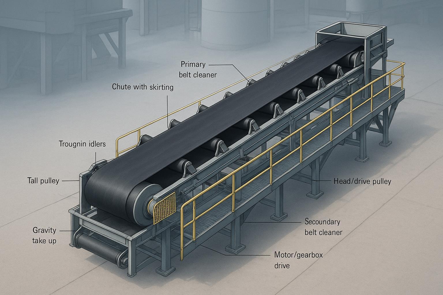
Think of a conveyor as a closed-loop roadway: the belt is the pavement; idlers are the roadbed; pulleys turn and tension the loop; the drive supplies motion; chutes and cleaners manage loading and discharge. When sized and aligned correctly, the belt conveys steadily with minimal wear and spill.
Formalized, an industrial belt conveyor system is a power-driven, continuous material-handling assembly in which an endless belt carries bulk or unit loads between loading and discharge points. It comprises the belt, pulleys, idlers, drive, tensioning, structure, and auxiliary devices—selected and verified against established practice and standards. CEMA’s governance and handbook materials define scope, nomenclature, and calculation frameworks; see the Conveyor Equipment Manufacturers Association’s overview of standards governance in the CEMA Operating Procedures Manual and the paid handbook reference page for Belt Conveyors for Bulk Materials, 7th Edition.
Core components and functions (plain-language)
Belt (textile or steel-cord). The moving, continuous member that both carries load and transmits tension. Textile belts are commonly standardized under ISO 14890 (construction, covers, adhesion), while steel-cord belts follow ISO 15236 families. Underground and hazardous-area belts reference ISO 22721 and flame/static tests in ISO 340 and ISO 284; consult official ISO catalogue entries via ISO/TC 41/SC 3.
Idlers/rollers. Carrying (troughing) idlers shape the belt into a trough (20°, 30°, 35°, sometimes 45°) to contain burden; impact idlers absorb loading shocks; return idlers support the empty belt; training idlers can nudge a drifting belt. Dimensional classes and nomenclature are set out in CEMA 502 committee materials.
Pulleys. Head/drive pulleys impart motion; tail pulleys redirect and provide wrap; snub and bend pulleys adjust wrap angle and routing; take-up pulleys add controlled tension. Design and ratings reference ANSI/CEMA B105.1 for welded steel pulleys and associated shaft/deflection criteria.
Drive assembly and controls. Motor, gearbox, and couplings deliver power; VFDs manage acceleration/braking; holdbacks prevent reverse run on inclines; sensors monitor speed, misalignment, and material flow.
Take-up/tensioning. Gravity or screw systems maintain belt tension within a target sag window so traction is reliable without over-tensioning.
Loading, discharge, and containment. Hoppers and chutes place burden in the center; skirting and wear liners confine and protect; cleaners (primary at the head pulley, secondary on the return strand) strip material to control carryback.
Structure and safety. Stringers, trusses, and galleries support components; walkways enable access. Guards and pull-cords address nip points and emergency stops per OSHA/ISO.
For a component-by-component nomenclature refresh and paid calculation framework, CEMA’s public change pages and excerpts provide context—see the CEMA change pages and a public Chapter 6 tension/power excerpt (legacy edition).
Standards landscape and when to use which
Designers frequently blend regional practice, corporate standards, and regulatory obligations. Here’s how the major families line up and where each shines.
CEMA — North American practice and widely used elsewhere. Provides the effective tension method (Te) and component standards for idlers and pulleys. Public excerpts outline variables and sizing logic; the full Belt Book is comprehensive.
DIN 22101 — A European framework emphasizing resistance categories and iterative convergence for tensions and power; widely applied in international projects and OEM tools.
ISO belt standards — Focus on belt construction, testing, and safety (textile vs steel-cord, flame/static resistance, storage/handling). These govern the belt as a product, complementing CEMA/DIN design methods.
OSHA + ISO machine safety — Guarding and control-of-hazardous-energy requirements for safe operation and maintenance.
Standard family | Primary scope | Typical use/region | When to prefer |
|---|---|---|---|
CEMA (Belt Book; CEMA 502; ANSI/CEMA B105.1) | Method for tensions/power; idler and pulley nomenclature/dimensions | North America; global OEM practice | You need a clear, widely adopted Te-based method and component classes |
DIN 22101 | Resistance classification; iterative design of power/tensions | Europe/international EPCs | Long/steep conveyors and projects standardized on DIN methodology |
ISO 14890/15236/22721/284/340/5285/13857/14119/14120 | Belt construction/testing, storage/handling; safety distances and interlocks; LOTO complements | Global | You must specify belt properties, safety testing, storage/handling, and guarding distances |
OSHA 1910.212/219/147 | Guarding and LOTO requirements (U.S.) | United States facilities | You operate in the U.S. and must align machine guarding and LOTO |
Citations and official pages for key items: the public CEMA Chapter 6 excerpt (method context), DIN 22101 overviews via Conveyor Belt Guide and a dynamics note by CDI (Belt Dynamics—An Alternative View), ISO catalogue entries such as ISO 5285 (storage/handling) and ISO 13857 safety distances, plus OSHA’s 1910.219 on power-transmission apparatus and machine guarding overview pages.
Applications and use cases
Mining and quarrying. High-tonnage ore and aggregate on long runs with terrain changes, often with multiple transfer points. Robust impact zones, high CEMA class idlers, and abrasion-resistant covers are typical.
Cement and building materials. Raw meal, clinker, and additives with high temperature and abrasiveness. Heat-resistant covers and robust cleaners are common.
Ports and logistics terminals. Ship-loaders/unloaders, stockyard belts, and reversible yard conveyors. Emphasis on dust control and corrosion resistance; variable-speed drives match berth operations.
Steel and power. Hot, heavy, sometimes sharp material with scale and fines; strong containment and chute design mitigate spillage and wear.
Manufacturing and packaging (unit handling). Flat belts for cartons/pallets, typically a different standards set but many principles (tension, tracking, guarding) carry over.
For steeply inclined or vertical bulk flow where conventional troughed belts would spill, engineered sidewalls and cleats maintain a pocketed cross-section. If you’re exploring that route, see BisonConvey’s product overview of sidewall belts for context on steep-angle applications and design considerations.
Selection and implementation workflow (CEMA/DIN aligned)
Here’s the deal: robust conveyors come from methodical, standards-aware choices—then a few iterations to land in the sweet spot between capacity, reliability, and cost.
Define material and duty
Bulk density (lb/ft³ or t/m³), lump size/shape, abrasiveness, stickiness, moisture, and temperature
Required capacity (t/h), operating hours/duty cycle, and layout (length, lift, curves, transitions)
Pick a belt width and trough geometry
Typical industrial widths range 600–1800 mm (available 400–2200+ mm). Common trough angles are 20°, 30°, 35° (sometimes 45° for high capacity). These ranges align with common industry practice reported by major manufacturers.
Select a target speed band
For many bulk materials, 1.5–3.5 m/s is a useful starting envelope; fragile or very abrasive material may run slower; free-flowing fines may run faster (up to ~4.5 m/s) where dust/spillage controls permit. A representative manufacturer example cites ~3.6 m/s for high-capacity systems.
Estimate resistances and effective tension (Te)
Sum primary, secondary, lift, and accessory resistances per your chosen method (CEMA Te or DIN categories). For CEMA-style variables and examples, review the public Chapter 6 excerpt and Rulmeca’s explainer on belt tensions.
Convert Te to power and verify traction
Power ≈ Te × v (v = belt speed). Confirm slack-side tension and wrap/lagging to avoid drive slip; if slip margin is low, review lagging, wrap angle, or take-up force before raising tension.
Size belt rating and select pulleys
Choose textile (ISO 14890 families) or steel-cord (ISO 15236) and set the tensile class with safety factors based on maximum steady-state and starting tensions. Select pulley diameters/face widths and crown/lagging per ANSI/CEMA B105.1 and manufacturer tables, checking shaft deflection and runout.
Check dynamics, starting/braking, and take-up travel
Verify acceleration torque, emergency stop/brake cases (prevent rollback on inclines), and ensure adequate take-up travel for splice growth and seasonal changes. Long/steep conveyors may require specialist dynamic analysis.
Iterate and document
Adjust width, speed, idler spacing, cleaner/skirt drag, and drive configuration until all constraints clear; record assumptions and references (standard numbers, OEM data) for the RFQ.
Compact worked example (illustrative only)
Goal: Move 800 t/h of crushed limestone (ρ ≈ 1.6 t/m³) on a 200 m conveyor with 15 m lift.
Capacity to volumetric flow: Qv = 800 t/h ÷ 1.6 t/m³ ≈ 500 m³/h.
Choose 1000 mm belt at 30° trough, target speed v ≈ 2.5 m/s (typical for this duty). Cross-section capacity for 1000 mm, 30° trough at 2.5 m/s comfortably clears 800 t/h in manufacturer tables (verify with your chosen standard and tables).
Preliminary resistances: using CEMA-style Te estimate (primary + secondary + lift + accessories). Lift force component ≈ mass flow × g × lift/speed; compute combined Te with method variables (Kx, Ky, etc.) per CEMA; validate with an internal calculator.
Power: P ≈ Te × v; check slack-side traction against head pulley wrap and lagging. If slip risk appears, add a snub to increase wrap or specify ceramic lagging before raising take-up force.
Belt class: With max tension from the Te calculation and safety factors, pick a textile EP belt class (per ISO 14890 family) or, if tensions are high/long runs, move to steel-cord (ISO 15236). Confirm minimum pulley diameters for the selected carcass and splice.
Finalize: Confirm take-up travel, starting/braking profile with the VFD, and accessory drag (cleaners, skirts). Iterate width/speed if margins are tight.
Note: Use the actual CEMA/DIN equations and OEM tables during design; the above is a scoping snapshot, not a substitute for formal calculation.
Common problems and troubleshooting (field-proven sequence)
Before any work: apply lockout/tagout and verify zero energy. Then observe, measure, adjust—one variable at a time.
Mistracking
Symptoms: belt walks to one side; frayed edge; material spillage at one edge.
Likely causes: off-center loading, out-of-square idlers or pulleys, seized/contaminated idlers, buildup on returns, damaged splice.
Corrective actions: center the feed; square frames and idlers; replace frozen idlers; clean pulleys/returns; inspect splice/edge damage; add training idlers or trackers only after root causes are corrected. For general tracking devices and transfer-point upgrades, see manufacturer resources such as Martin’s tracker overview and transfer-point design brochures.
Slippage at the drive
Symptoms: speed drop, heating at the head pulley, rubber dust, control alarms.
Likely causes: low tension, worn/contaminated lagging, wet/sticky belt surface, excessive startup torque.
Corrective actions: adjust take-up to design setpoint; clean or re-lag the pulley (ceramic lagging can raise friction); add a snub pulley to increase wrap; review load and start profile. Manufacturer explainers discuss diagnosing inadequate power and lagging selection.
Spillage in the load zone
Symptoms: piles under the loading chute, dust, premature skirt wear.
Likely causes: poor chute geometry, misaligned loading, inadequate skirt contact, excessive drop height.
Corrective actions: re-center the stream; upgrade chute liners and geometry; set skirts correctly with even pressure; reduce drop height with rock boxes or spoon chutes.
Carryback on the return strand
Symptoms: buildup on return idlers, housekeeping burden, material on tail pulley.
Likely causes: insufficient primary/secondary cleaning, wrong blade material, poor cleaner pressure/angle, sticky fines.
Corrective actions: set a robust primary at the head pulley and a secondary on the return; verify torque/pressure settings; replace worn blades; consider V‑plows ahead of the tail pulley.
Representative technical overviews supporting the above include manufacturer and standards-adjacent publishers: see Martin Engineering’s carryback page and tracker/transfer resources, and Flexco’s troubleshooting blogs. For Te/power context when diagnosing slip, the public CEMA excerpt and Rulmeca explainers are useful.
Best practices and maintenance
Inspection cadence and focus
Daily/shiftly: look/listen for abnormal noise or heat; verify belt cleaners’ contact; check load centering and return buildup.
Weekly: spin/idler rotation checks; clean head/tail pulleys; verify take-up position and travel margin; sample carryback.
Monthly/quarterly: alignment survey (laser/smart level); check pulley runout and lagging wear; inspect splices (visual and NDT where applicable); assess skirt wear and seal pressure.
Cleaner setup
Primary scraper close to the head pulley with proper tip pressure; secondary cleaners on the return with even load; re-tension per OEM guidance. Cleaner drag varies—plan accessory power accordingly; see a technical explainer on cleaner drag for estimating loads.
Storage and handling of spare belts
Follow ISO 5285 storage/handling guidance to avoid deformation, heat/UV damage, and contamination. Keep rolls off the ground on cradles, away from ozone/solvents, and rotate periodically for long-term storage.
Safety, guarding, and LOTO
Guard nip points and rotating parts per OSHA 1910.219 power‑transmission apparatus and 1910.212 machine guarding; apply lockout/tagout per OSHA 1910.147. Where interlocked access is used, apply ISO 14119 logic and guard design in line with ISO 14120; use safety distances per ISO 13857. Always verify local regulations and complete a task-specific risk assessment.
RFQ/specification checklist (ready-to-use prompt)
Use this list to brief vendors and align engineering with procurement. Keep it concise and standards-referenced.
Application/material: density, lump size, abrasiveness, moisture, temperature
Duty/capacity: t/h, m³/h, operating hours; layout (length, lift, curves)
Belt: width, target speed, carcass type (EP/NN vs steel-cord), tensile class, cover grade/thickness, safety tests (ISO 284/340/22721 as applicable), splice type
Idlers: trough angle, spacing, return type, sealing, CEMA class or ISO class
Pulleys: diameters/face widths, crown/lagging type (ceramic/rubber), compliance with ANSI/CEMA B105.1; shaft/deflection criteria
Drive & controls: motor power, gearbox, VFD, backstop, voltage/frequency, environment rating
Take-up: gravity/screw, travel allowance
Accessories: primary/secondary cleaners, V‑plow, skirts, chute liners, dust control
Safety: guarding approach, pull‑cords, interlocks, safety distances (ISO 13857), LOTO referent (OSHA 1910.147)
Standards to cite: CEMA Belt Book method; DIN 22101 (if used); ISO families for belt and safety items
Conclusion and next steps
Conveyors succeed when every decision—from belt width to cleaner pressure—maps back to recognized standards, measured site conditions, and a disciplined maintenance routine. If you document assumptions, verify tensions and traction, protect nip points, and keep the load centered and the belt clean, you will eliminate most chronic failures before they start.
Next steps: finalize your RFQ fields, choose a calculation method (CEMA or DIN), and line up component vendors who can support standard-compliant selections. If you need a single point of contact for belts, idlers, and pulleys, visit BisonConvey to discuss a specification aligned to your material and duty profile.