How to Calculate Conveyor Belt Tension
Correct belt tension is the backbone of reliable conveying. Size it too low and you’ll fight slip, drift, and spillage. Push it too high and you’ll overload the carcass, shorten splice life, and drive up energy and component wear. This guide shows you, step by step, how to calculate conveyor belt tension for troughed bulk-material conveyors so you can select belts, pulleys, and take-up systems with confidence.
We’ll cover both the CEMA “effective tension” approach and the DIN 22101 resistance method, then resolve tight-side (T1) and slack-side (T2) drive tensions with the capstan equation. You’ll see a worked SI example (with an imperial quick check), sag and take-up rules of thumb, and practical troubleshooting when calculated and measured values don’t align.
Key takeaways
-
“How to Calculate Conveyor Belt Tension” centers on the net drive force Te and its translation to T1 and T2 at the drive.
-
CEMA decomposes Te into resistances and elevation; DIN 22101 partitions total resistance similarly—both map to power P = Te · v.
-
Always check two limits for the slack side: slip at the drive and sag on the carry/return run; select the larger T2.
-
Use Euler–Eytelwein (capstan) with wrap angle and lagging friction to set T1/T2; add startup margins or soft-starts when necessary.
-
Tension affects belt rating, minimum pulley diameters, take-up size/travel, and idler selection; re-verify during commissioning.
Core concepts and definitions
-
Effective tension (Te): The net tangential force at the drive required to overcome frictional resistances, lift the load, and run accessories. Te maps directly to power via P = Te · v.
-
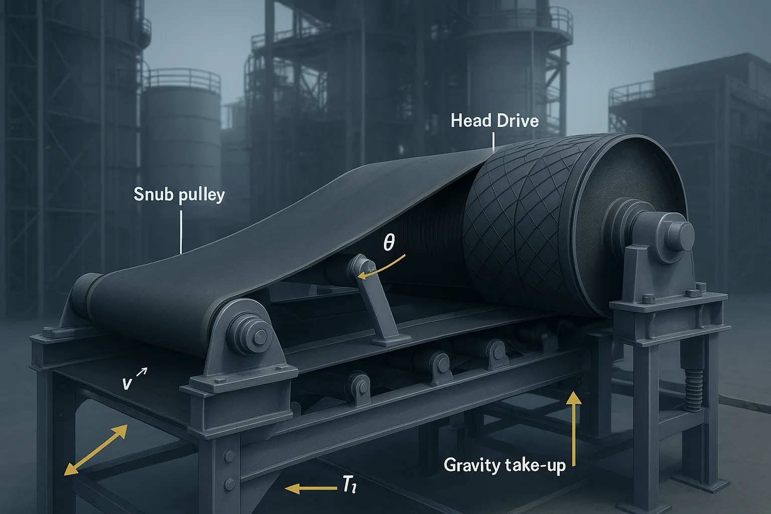
Tight-side and slack-side drive tensions (T1, T2): The two belt pulls around the drive pulley such that T1 − T2 = Te. T2 must be high enough to avoid slip and maintain acceptable sag.
-
Wrap angle (θ): The contact angle (in radians) between the belt and drive pulley. Increased wrap (snub pulleys) raises the T1/T2 ratio available before slip.
-
Coefficient of friction (μ): Effective friction between belt and lagging at the drive. Rubber lagging often 0.3–0.5 in clean, dry conditions; ceramic can be higher; real values vary with pressure and speed according to manufacturer tests and field reports.
-
Sag percentage (% sag): Midspan belt deflection divided by idler spacing. Typical design targets on the carry run are ~1–2% depending on loading zone; return run can be higher. Sag is controlled by take-up tension.
-
Take-up: Device that maintains belt tension (screw, gravity/counterweight, hydraulic). Travel must accommodate installation/creep/stretch and dynamic transients.
For a refresher on components and where tensions act, see this primer on system components in the article What is a conveyor system?.
Calculation frameworks: CEMA vs DIN 22101
CEMA effective tension (historical formulation)
CEMA’s widely taught expression breaks Te into components such as rolling resistance on carry/return, belt and material flexure, elevation lift, and accessory drag. A commonly referenced public expression (consistent with CEMA practice) is:
Te = L · Kt · (Kx + Ky · Wb + 0.015 · Wb) + Wm · (L · Ky + H) + Tp + Tam + Tac
Where, in plain language:
-
L is the conveyor length; Kt a temperature factor.
-
Kx captures idler/bearing/rolling resistance; Ky captures belt and material flexure; Wb, Wm are belt and material weights per unit length.
-
H is total lift; Tp covers pulley/flex losses; Tam and Tac add the material acceleration and accessory resistances.
Power follows directly: P = Te · v (kW when Te is in newtons and v in m/s). For a step-through of this method and sag logic in North American practice, see the Rulmeca explainer How to Calculate Conveyor Belt Tensions and the public CEMA excerpt Belt Book, Chapter 6 (PDF excerpt).
DIN 22101 resistance method (overview)
DIN 22101 partitions the total motion resistance into primary (FH), secondary (FN), gradient/elevation (FSt), and special (FS). The sum FW ≈ Te for steady-state, and power PW = FW · v. The approach emphasizes an equivalent rolling resistance factor for belt-plus-load and treats elevation explicitly. See the official catalog summary DIN 22101 calculation basis and the ISO power/tension scope in ISO 5048:1989 (public outline/PDF).
Comparison: when to use which
Both methods are accepted if applied consistently and with realistic inputs. In practice, North American OEMs often favor CEMA tables/coefficient selection; European and many global tools implement DIN 22101 or ISO 5048 style resistance factors.
Worked example: How to Calculate Conveyor Belt Tension (SI)
Scenario: Troughed belt, L = 200 m center-to-center, total lift H = 12 m, belt speed v = 2.5 m/s, well-maintained idlers, single drive with 210° wrap and rubber lagging.
Assumptions and inputs (clearly stated):
-
Belt mass per length m_b = 22 kg/m (textile EP belt, mid-size range).
-
Throughput Q = 600 t/h; material bulk density ρ ≈ 0.9 t/m³.
-
Material mass per length m_m = (Q/3600) / v = (600,000 kg/h ÷ 3600) ÷ 2.5 ≈ 66.7 kg/m.
-
Equivalent rolling resistance factor f = 0.02 (good idlers, clean belt; representative first-pass DIN value).
-
Accessory/cleaning drag F_acc = 1,000 N (skirt plus cleaners; estimate for calculation).
-
Drive wrap θ = 210° = 3.665 rad; lagging friction μ = 0.35 (rubber lagging, dry, representative value).
-
Carry idler spacing a = 1.2 m; target carry sag = 1%.
Step 1 — Primary resistance and elevation (DIN-style first pass)
-
Total specific weight w = (m_b + m_m) · g = (22 + 66.7) · 9.81 ≈ 870.8 N/m.
-
Primary/rolling resistance (FH) ≈ w · f · L = 870.8 · 0.02 · 200 ≈ 3,480 N.
-
Elevation (FSt) = (m_m · g) · H = (66.7 · 9.81) · 12 ≈ 7,848 N.
-
Accessories (FS) = F_acc = 1,000 N.
-
Effective tension Te ≈ FH + FSt + FS = 3,480 + 7,848 + 1,000 ≈ 12,330 N.
Step 2 — Power
- P = Te · v / 1000 = 12.33 kN · 2.5 m/s ≈ 30.8 kW.
Step 3 — Resolve T1 and T2 from Te using Euler–Eytelwein
-
Capstan relation at the slip limit: T1 / T2 = e^(μθ) = e^(0.35 · 3.665) ≈ 3.607.
-
Also, T1 − T2 = Te = 12,330 N.
-
Solve: r = 3.607; T2_slip = Te / (r − 1) ≈ 12,330 / 2.607 ≈ 4,730 N; T1 = Te + T2 ≈ 17,060 N.
Step 4 — Sag check and take-up baseline
-
Using a catenary approximation for carry sag s = 1% and span a = 1.2 m, required midspan tension T0 ≈ (w · a) / (8 · s) = (870.8 · 1.2) / (8 · 0.01) ≈ 13,060 N.
-
Slack-side requirement from sag: T2_sag ≈ 13 kN, which governs over the slip-based 4.7 kN. Select T2 = 13 kN; then T1 = Te + T2 ≈ 25.3 kN.
Result snapshot
- Te ≈ 12.3 kN; P ≈ 30.8 kW; T2 (governed by sag) ≈ 13 kN; T1 ≈ 25.3 kN.
Imperial quick check (power)
-
Convert Te to lbf: 12,330 N ≈ 2,773 lbf. Belt speed v ≈ 2.5 m/s = 492 fpm.
-
Horsepower HP ≈ (Te[lbf] · fpm) / 33,000 ≈ 2,773 · 492 / 33,000 ≈ 41 HP.
Optional verification tool
- You can run the same inputs through the BisonConvey tension calculator to validate Te and power and to iterate on sag and take-up settings.
Notes on assumptions
- The f value and accessory drag should be justified by idler class/condition, sealing, cleaners, and skirts. When available, a CEMA coefficient-based calculation can cross-check the DIN estimate before you finalize component selection.
Startup vs steady-state: acceleration and slip margins
Steady-state calculations set your baseline. During startup and acceleration, tensions can peak significantly higher due to accelerating the belt and the material stream. CEMA formulations include Tam (material acceleration) and Tac (accessories), and field experience often observes 30–40% above running tension for direct-on-line starts on loaded belts. Soft-starts and variable-frequency drives (VFDs) can reduce peaks and slip risk while limiting shock into the belt and splices. For the CEMA and tutorial context, see the public excerpt CEMA Belt Book, Chapter 6 and a concise overview of Te and startup components in Rulmeca’s explainer.
What to do in practice: ramp with a VFD or soft-start, stage loading, and confirm that T2 during startup still exceeds both slip and sag requirements—consider a snub for more wrap or higher-μ lagging if margins are tight.
Selection and implementation guidelines
-
Belt rating and carcass type: Choose a belt with a rated allowable working tension above your T1 with an appropriate safety factor, per textile belt spec ISO 14890 and steel-cord families ISO 15236 (catalog pages). Manufacturer catalogs map belt ratings to minimum pulley diameters; always verify splices against those tables.
-
Minimum pulley diameters: Confirm against ISO 3684 catalog guidance and manufacturer tables for pulley group and minimum diameters based on tension utilization and splice type.
-
Drive and wrap: If the T1/T2 margin is small, increase wrap with a snub, change lagging to ceramic, or split power across multiple drives to reduce T1 on any single pulley. The governing physics is the capstan relation T1/T2 = e^(μθ).
-
Take-up type and travel: For long/high-tension conveyors, a gravity take-up generally gives steadier tension than a screw take-up. Reserve travel is commonly on the order of ~2% of the center distance (refine for expected elastic stretch and creep). Leave additional travel for commissioning stretch-in.
-
Idlers and rolling resistance: Quality, sealing, and spacing drive the rolling resistance and therefore Te. Poorly aligned or contaminated idlers raise f (or Kx/Ky), increasing power and required take-up force. Read more on idler behavior and maintenance in Belt conveyor idlers—definition and importance.
For how sag and take-up travel interact with transitions and layout choices, see Belt conveyor system design—ultimate guide. If you are weighing carcass tradeoffs for tension and pulleys, compare textile and steel-cord construction in EP vs steel cord conveyor belts—comparison.
Common problems and troubleshooting
-
Drive slippage at startup or wet conditions
-
Likely causes: Insufficient T2 margin, low μ (wet/rubber lagging), inadequate wrap.
-
Checks: Recalculate T1/T2 with realistic μ and θ; consider ceramic lagging or added snub; verify gravity take-up mass.
-
-
Excessive carry-run sag, spillage in loading zone
-
Likely causes: Insufficient take-up force, too-long idler spacing, underloaded belt (low m_m).
-
Checks: Use the sag formula with actual w and a; reduce spacing in loading zone; increase take-up tension within belt rating limits.
-
-
Higher than expected power draw
-
Likely causes: Dirty or seized idlers (raised f/Kx), heavy cleaner loads, misalignment creating side drag.
-
Checks: Inspect and spin idlers, measure accessory loads, confirm frame and pulley alignment; compare measured Te via power to your calculation.
-
-
Belt mistracking and edge wear
-
Likely causes: Structure not square, off-center loading, uneven idler trough, or stiff splice.
-
Checks: Follow a structured alignment procedure; correct loading chutes; use training idlers sparingly and as a last resort. For step-by-step commissioning and alignment procedures, see Conveyor belt installation—ultimate guide.
-
Best practices and maintenance tips
-
Document assumptions: Record f or Kx/Ky, μ, θ, idler spacing, sag targets, and accessory loads. These drive Te and should be auditable.
-
Verify in the field: During commissioning, record no-load and staged-load power; back-calculate Te = P/v and compare to your model. Adjust take-up to hit sag targets.
-
Control contaminants: Clean carry and return rolls; maintain skirts and cleaners to the manufacturer’s force/tension specs; shield lagging from mud buildup that lowers μ.
-
Re-check after changes: Any change in belt type, cleaners, skirt geometry, idler class, or speed requires a quick re-run of Te and T1/T2.
-
Plan take-up travel: Leave reserve for growth and creep; inspect and reset seasonally if temperature swings are large.
Conclusion: Actionable next steps
-
Model Te with either CEMA coefficients or DIN resistance f—be explicit about assumptions and units.
-
Check both slip and sag; set T2 to the governing requirement, then compute T1 = Te + T2.
-
Confirm power P = Te · v, belt rating, minimum pulley diameters, wrap/lagging, and take-up type/travel.
-
Validate in the field by comparing measured power to your calculation, and adjust take-up to meet sag targets without over-tensioning.
If you’d like a second set of eyes on your calculation or help matching belts, idlers, pulleys, and take-up hardware to your tension results, our engineering team at BisonConvey supports standards-aligned selection and custom solutions.
Selected references (authoritative anchors)
-
Rulmeca—How to Calculate Conveyor Belt Tensions (tutorial consistent with CEMA practice).
-
CEMA Belt Book, Chapter 6 (public excerpt) (effective tension and P = Te·v context).
-
DIN 22101 calculation basis—catalog page (resistance method definitions).
-
ISO 5048:1989—public outline/PDF (operating power and tensile forces).
-
ISO 14890—catalog page (textile belt specifications and test methods).