
Belt Conveyor System Design Guide
Comprehensive, standards-aligned ultimate guide to belt conveyor system design: calculations, component selection, troubleshooting, and maintenance. Read now.
Meta title: Belt Conveyor System Design Guide — Design & Best Practices
Meta description: Comprehensive, standards-aligned guide on belt conveyor design—calculations, component selection, troubleshooting, and maintenance for engineers.
Belt Conveyor System Design Guide
Designing a reliable belt conveyor is equal parts math, standards literacy, and field experience. Done well, it delivers stable operation, lower total cost of ownership, and a safer plant. This Belt Conveyor System Design Guide distills proven engineering practice—anchored to CEMA, ISO, DIN, and ASME/OSHA—into a practical workflow you can apply to bulk material handling conveyors in mining, cement, logistics, steel, power, and manufacturing.
Key takeaways
Start with the material: bulk density, surcharge angle, lump size, moisture, and abrasiveness drive belt width, speed, trough angle, idler type, and chute design.
Choose a calculation method and stay consistent. CEMA and ISO/DIN produce comparable answers when inputs are realistic and assumptions are clear.
Control belt sag and transitions. Target about 3% running sag, design proper transition lengths, and respect minimum pulley diameters to prevent edge overstress and premature fatigue.
Reliability is designed in. Centralized loading, correct idler spacing, adequate sealing, and appropriate cleaners reduce carryback, spillage, and power draw.
Safety is not optional. Apply guarding and emergency stop practices from ASME B20.1 and OSHA 1910 during design, commissioning, and maintenance.
Core concepts and principles
A belt conveyor is a continuous system moving bulk solids on a flexible belt supported by idlers and driven by pulleys. Design begins with the material and the required capacity.
Material characterization
Bulk density ρ controls mass flow. Moisture affects stickiness and rolling resistance. Abrasiveness drives cover compounds and chute wear liners. Lump size sets belt width, skirtboard gaps, and impact idler class.
Surcharge angle governs how the material “heaps” on the troughed belt. Higher trough angles carry more but increase edge tension. Use lab-tested values where available.
Capacity fundamentals
Throughput C depends on cross-sectional area A of the load, belt speed V, and bulk density ρ: C = ρ × V × A. Trough geometry (20°, 35°, 45° three‑roll idlers) defines A. Designers often size to about 85% of the theoretical area to add surge margin and reduce spillage risk, an approach reflected in industry practice summarized in Martin Engineering’s Foundations and supported by CEMA tables. See the CEMA 7th Edition preview for methodology and corrected tables references in the public domain under CEMA materials.
Free-edge distance matters. Ensure adequate gap between the material edge and belt edge to avoid loss at transitions and curves.
Belt speed selection
Faster belts increase capacity for a given width but can raise dust, noise, degradation, and wear. Typical industry ranges vary by commodity (e.g., 1.5–4.0 m/s for coal, 2–5 m/s for ores/aggregates; verify against site goals and standards-based guidance). Balance energy, containment, and material integrity. For background on practice and impacts, see the Rulmeca retrofit case context and Martin Engineering application notes; for final design, validate with tables and test data from CEMA and OEMs.
Belt Conveyor System Design Guide methods and standards
Two families of methods dominate power and tension calculations. What’s the real difference, and which should you use?
CEMA methods rely on empirically derived factors (e.g., Ky for idler indentation rolling resistance) coupled with geometry and material inputs. Under conventional conditions, the Universal method aims for about ±10% accuracy when inputs are realistic, as discussed in an engineering summary on the CEMA horsepower equation evolution.
ISO/DIN approaches (ISO 5048, DIN 22101) model resistances with a base friction factor f and adjustments. They emphasize standardized symbol sets, wrap angles, and safety factors. Both methods can converge when tuned to the same physical conveyor.
Below is a concise comparison for quick orientation.
Aspect | CEMA 7th Edition approach | ISO 5048 / DIN 22101 approach |
|---|---|---|
Friction model | Empirical resistance factors (e.g., Ky, Kt) tied to idler pitch, belt tension, temperature | Base friction factor f with additive components; standardized framework |
Inputs emphasis | Trough geometry, sag criteria, Ky charts, installation conditions | Global f, wrap angles, standardized symbol set, safety factors |
Accuracy notes | Universal method targets about ±10% under conventional conditions when inputs are realistic | Often conservative unless tuned to field measurements |
Regional use | Predominant in North America and many global OEMs | Common in Europe and international EPCs |
When to choose | Brownfield upgrades with known CEMA data; plants with local CEMA expertise | Multinational specs referencing ISO/DIN; projects requiring harmonized symbols |
For authoritative references and deeper reading, consult the CEMA 7th Edition preview and errata, ISO 5048’s official scope page, and DIN 22101 product listings on DIN Media/Beuth.
Components and selection
Getting the components right is half the battle. The following guidance summarizes belt constructions, idlers, pulleys, and take-up systems with pragmatic selection cues.
Belts — fabric vs steel cord
Fabric belts (EP/NN) and steel‑cord belts serve different tension ranges and duty cycles. ISO 14890 covers textile belts, while ISO 15236‑1 covers steel‑cord belts. Minimum pulley diameter methodology is in ISO 3684; many manufacturers publish conservative tables.
Attribute | Fabric belts (EP/NN) | Steel‑cord belts |
|---|---|---|
Typical tensile range | Low to medium (e.g., 200–1250 N/mm) | Medium to very high (e.g., 1000–10000+ N/mm) |
Working elongation | Higher; more stretch, easier splicing | Lower; stable length, longer transitions needed |
Splice type | Mechanical or hot/cold vulcanized | Primarily hot vulcanized; long step splices |
Minimum pulley diameters | Larger than steel cord at same tension rating; verify per ISO 3684 and OEM | Smaller than fabric at same tension rating; verify per ISO 3684 and OEM |
Typical applications | Short to medium conveyors, mobile plants, general industry | Long overland, high‑lift, high‑tension mining/ports |
Idlers and spacing
Trough angles of 20°, 35°, and 45° are common. Higher trough angles increase capacity at the same width but demand better containment and can raise edge stress.
Space troughing idlers to limit running sag to about 3% of span; some high‑angle or dusty applications target lower sag. Bearing life targets typically fall in the 60,000–100,000 h range depending on load and class; confirm with your chosen OEM and apply ISO 281 for L10 life calculations.
Choose sealing and materials for the environment: labyrinth seals and dust caps for fines; stainless or polymer coatings for corrosive service; impact idlers in loading zones.
Pulleys
Respect minimum pulley diameters determined by belt construction, cover thickness, and splice type. ISO 3684 defines methodology. Many mining belt catalogs include diameter tables; for example, Fenner Dunlop’s mining brochure shows diameter selections across duties and tensions.
Lagging improves traction and reduces slip. Diamond ceramic lagging is common on drive pulleys in wet service; plain or smooth rubber may suffice elsewhere.
Size shafts for deflection and fatigue. Keep bearing loads within catalog ratings; provide clearance for guards and belt cleaners.
Take‑up systems
Gravity take‑ups offer stable tension across load changes and startup, at the cost of space. Screw and hydraulic systems are compact but require careful setting and monitoring.
Allow adequate travel—often on the order of 1–2% of belt length—accounting for elastic stretch, temperature, and splice seating. Ensure safety stops and guarding per ASME B20.1 and OSHA.
Design workflow and worked example
Let’s walk through a compact, standards‑aligned workflow and a simple example. Think of this as a “sanity check” path you can adapt to your preferred method.
Step 1 — Define the duty
Target: 800 t/h of crushed rock (ρ ≈ 1.6 t/m³), max lump 150 mm, moisture moderate, abrasive. Elevation change modest, straight run, outdoor.
Step 2 — Pick a belt width and trough angle
Start with 800 t/h and screening for lump‑to‑width ratio. A 600 mm belt often handles up to ~150 mm lumps with appropriate skirts and chute design. Choose 35° troughing idlers for a good capacity/containment balance.
Step 3 — Select a tentative speed
Trial V = 2.5 m/s to limit degradation and dust while keeping the conveyor compact.
Step 4 — Check cross‑sectional area and capacity
Using standard trough geometry relationships, approximate the cross‑sectional area A for 600 mm at 35°. Designing to ~85% theoretical capacity is prudent. If A × V × ρ ≈ 800 t/h at 85% loading, continue; if not, iterate speed or width. For example, if A ≈ 0.27 m² at full theoretical for this configuration, effective A ≈ 0.23 m²; capacity ≈ 1.6 × 2.5 × 0.23 ≈ 0.92 t/s ≈ 3310 t/h—clearly too high for our needs, signaling that even at lower speed we have margin. We can reduce speed for wear/noise or keep margin for surges. A more realistic A for 600 mm/35° would be smaller; designers consult CEMA tables and OEM charts to refine this step.
Step 5 — Choose a calculation method and estimate power/tension
Decide on CEMA or ISO/DIN. Apply consistent resistances, lift, skirt friction, and an appropriate service factor. For a conceptual estimate, CEMA’s Universal method or ISO 5048 with a calibrated f can both yield a close result when fed with realistic idler and belt data. For an overview of how CEMA horsepower prediction evolved, see the Bulk‑Online technical article discussing method development.
Step 6 — Set idler spacing from sag limits
Target running sag of ~3%. With belt tension T, belt modulus, and load per meter known, calculate pitch to satisfy the sag criterion. Heavier, stiffer belts at higher tensions allow longer spacing; light, low‑tension belts require shorter spacing. Validate against CEMA sag guidance and adjust loading zone spacing shorter for impact control.
Step 7 — Design transitions
Provide adequate flat‑to‑trough and trough‑to‑flat transition distances to avoid edge overstress. Use progressive transition idlers—e.g., a 20° set before 35°, and an extra stage for 45° troughs. Research shows pulley elevation relative to the belt line strongly affects required transition length; placing the pulley at the belt line may demand a much longer transition than an optimized elevation. See the classic Bulk Solids Handling paper on belt conveyor transition geometry for the underlying rationale and example calculations.
Step 8 — Check minimum pulley diameters
Apply ISO 3684 methodology or a conservative OEM table to confirm drive, tail, and bend pulley diameters for the selected belt and splice. If on the cusp, moving up one diameter class can materially extend belt life by reducing bending strain, as echoed by common rules‑of‑thumb.
Step 9 — Finalize take‑up and controls
Size gravity take‑up mass or screw/hydraulic travel for startup and thermal effects. Add pull‑cords and E‑stops at appropriate intervals along walkways; confirm guarding per ASME B20.1 and OSHA 1910.
Quick Imperial equivalence
2.5 m/s ≈ 492 fpm; 800 t/h ≈ 882 short tph; 600 mm ≈ 24 in.
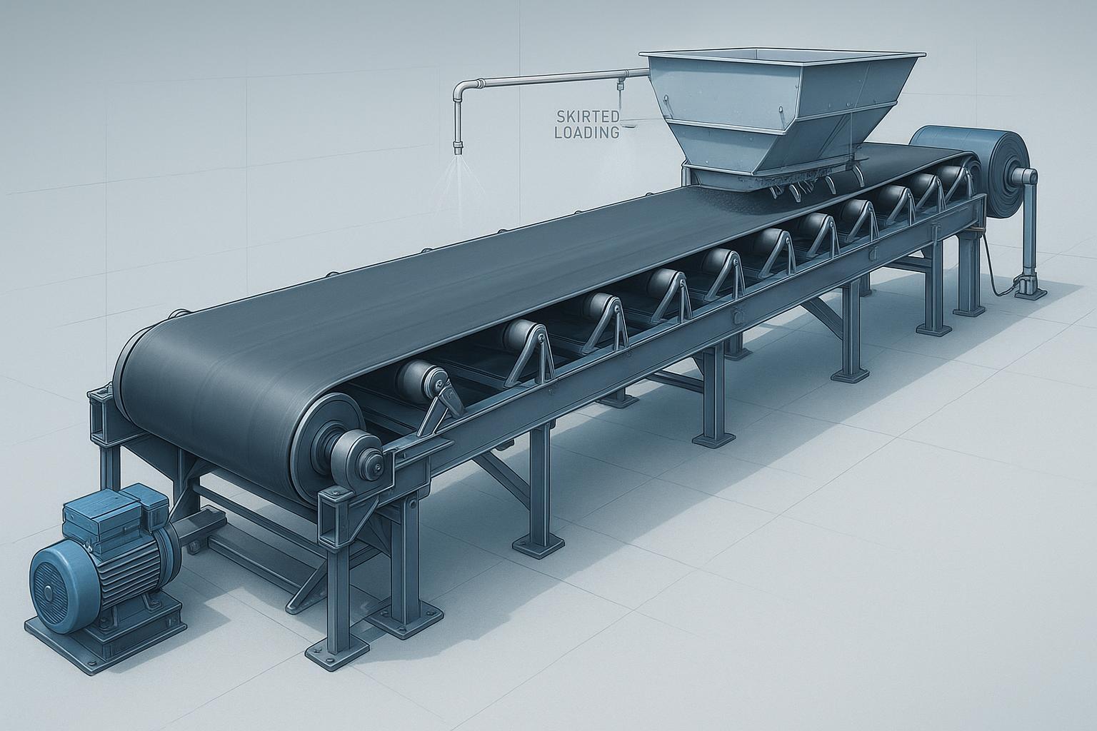
Transfers and loading zones
The loading zone determines half of your reliability story. Good design centralizes the stream, minimizes impact, and controls dust and spillage.
Use impact idlers or beds under the drop zone. Size for lump energy and ensure stiffness continuity to avoid belt “piano string” effects.
Keep skirts tight and parallel, with adjustable clamps and wear liners. Avoid excessive sealing drag by matching skirt length to actual containment needs and by using low‑friction liners.
Aim the incoming stream to match belt speed and centerline. Poor chute geometry causes mistracking, dust, and liner wear. Martin Engineering’s Foundations reference provides detailed best practices for chute angle selection, wear lining, and airflow management.
Install primary and secondary cleaners compatible with your belt compound and splice type to control carryback and reduce fugitive material.
Commissioning, troubleshooting, and maintenance
Commissioning
Verify alignment of pulleys, idlers, and structure before splicing. Tension the belt per construction and splice recommendations. Test all pull‑cords, E‑stops, and interlocks. Confirm guards are secure at nip points and rotating parts in line with ASME B20.1 design provisions and OSHA 1910 machine guarding rules.
Troubleshooting cues linked to design choices
Mistracking tends to trace back to off‑center loading, skewed idlers, or inadequate trough transitions. Start by inspecting the loading zone and the first three idler sets; then check frame squareness and pulley faces. Correct the cause rather than overtightening trackers.
Excessive carryback suggests cleaner selection or installation issues, damaged scraper blades, or insufficient belt tension at the head pulley. Review cleaner type vs material stickiness and verify take‑up settings.
Spillage often indicates too much sag, inadequate skirt sealing, or free‑edge distances that are too small. Recalculate idler spacing from the sag criterion and inspect skirtboard geometry.
High power draw can result from seized idlers, misalignment, over‑tight skirts, or material buildup in the return path. Condition-monitor idler temperature and vibration; loosen skirts if drag is unnecessary.
Maintenance and condition monitoring
Inspect idlers for noise, heat, and runout during routine walks. Replace before bearing failure escalates into belt damage.
Track power consumption trends. A rising baseline often reveals idler deterioration or material buildup long before a stoppage.
Use infrared and ultrasound where practical to catch early bearing failures. Log adjustments to skirts and cleaners to correlate with energy draw and spillage trends.
For comprehensive safety language and scope boundaries, see ASME’s Safety Standard for Conveyors and Related Equipment and OSHA 1910 Subpart O on machinery guarding and nip points.
Procurement and specification
Clear specifications reduce risk and shorten lead times. Provide the following data when engaging suppliers and OEMs.
Material data: bulk density, surcharge angle, lump size, moisture, abrasiveness, temperature, corrosiveness.
Duty: capacity range, belt speed if fixed, elevation change, length, geometry, environment, ambient temperature range.
Belt: width, construction (textile or steel cord), rating, cover grade/thickness, splice type, minimum pulley diameters by station.
Idlers: trough angle, diameter, spacing target from sag criterion, sealing class, bearing life target, environmental protection.
Pulleys: face width, lagging type, shaft diameter/deflection criteria, bearings, take‑up type/travel.
Safety and compliance: guarding expectations, pull‑cord and E‑stop layout preferences, inspection access.
A neutral micro‑example
For a 600 mm, 2.5 m/s limestone conveyor outdoors, a buyer might request textile EP 500/3 with 6+2 mm covers, hot‑vulcanized splice, 35° troughing idlers at spacing calculated for ~3% sag, diamond lagged drive pulley sized per ISO 3684, and a gravity take‑up with 1.5% travel. A supplier such as BisonConvey can provide belts, idlers, and pulleys to these parameters and collaborate on take‑up and cleaner choices based on site conditions.
If you are shortlisting vendors, you may also find value in a procurement‑focused perspective like this internal guide on evaluating suppliers: see the engineering‑oriented discussion in the article on the best conveyor belt suppliers for 2026.
Glossary of practical terms
Surcharge angle: The angle formed by the free surface of bulk material on a moving belt; used to compute cross‑sectional area in a trough.
Free‑edge distance: The horizontal gap between the material edge and the belt edge; a containment and spillage control parameter.
Running sag: The maximum vertical deflection between idlers during operation, often limited to about 3% of the pitch to control spillage and tracking.
Transition distance: The length required for the belt to form from flat to troughed and back; prevents edge overstress.
Indentation rolling resistance: Energy loss as the belt deforms over idlers; a major contributor to steady‑state power.
References and further reading
CEMA 7th Edition preview and errata provide scope and methodology context for capacity, power, and installation tolerances. See the official CEMA 7th Edition preview and the CEMA errata page for corrections to first printings.
ISO 5048 outlines operating power and tensile force calculations for conveyors with carrying idlers; DIN 22101 defines the European dimensioning framework. Use the official ISO scope page and DIN Media listings for authoritative scope descriptions.
The evolution of CEMA horsepower prediction and comparisons to ISO/DIN friction models are summarized in a technical article hosted by Bulk‑Online.
For comprehensive field best practices on transitions, chute design, dust control, and troubleshooting, consult the Martin Engineering Foundations book.
Minimum pulley diameter selection examples appear in mining catalogs such as the Fenner Dunlop Americas mining brochure.
Safety and guarding design scope and obligations are established in ASME B20.1 and OSHA 1910 Subpart O regulations.
Conclusion and next steps
Here’s the deal: robust belt conveyor design is about disciplined inputs, a consistent calculation method, and reliability‑by‑design details that prevent the usual failures before they start. Use defensible material data, select belt width and speed with containment margin, control sag and transitions, and enforce safety from day one. That’s how you keep uptime high and power draw steady.
If you are drafting specifications or refining component choices for a project, share your duty parameters and constraints. A practical next step is to review belts, idlers, pulleys, and take‑up options against the design criteria outlined in this Belt Conveyor System Design Guide and to line up installation and commissioning checks before materials arrive. For component sourcing and application discussion, you can request a technical review and options from an industrial supplier such as BisonConvey—keep the brief factual, include constraints, and expect a standards‑aligned response.
SEO notes inside the copy
Primary keyword used in the H1 and once more in a section heading, as well as several times in the body. Secondary phrases like belt conveyor design calculations, CEMA belt conveyor standards, ISO 5048 conveyor calculation, conveyor belt width selection, idler spacing and troughing angle, minimum pulley diameter, belt tension and power, conveyor maintenance best practices, troubleshooting conveyor problems, and bulk material handling conveyors have been incorporated naturally.
External source anchors used once each in the article body for authority
CEMA 7th Edition preview: authoritative method scope and tables. https://cemanet.org/cema-7th-edition-preview/
CEMA errata and appendix references: corrections and installation standards access. https://cemanet.org/cema-7th-ed-belt-book-errata/ and https://cemastore.com/product/cema-pdf-conveyor-installation-standards-7th-ed-appendix-d/
ISO 5048 scope page: official calculation standard description. https://www.iso.org/standard/11069.html
DIN 22101 listing on DIN Media/Beuth: basis for calculation and dimensioning. https://www.dinmedia.de
Bulk‑Online technical article on CEMA horsepower methodology. https://www.bulk-online.com/en/article/technical-article/cema-horsepower-equation-development-new-conveyor-power-prediction
Martin Engineering Foundations book PDF for best practices. https://www.martin-eng.com/sites/default/files/Foundations/Book%20Downloads/f4-2012.pdf
Fenner Dunlop Americas mining brochure with pulley diameter tables. https://fennerdunlopamericas.com/app/uploads/fda-mining-brochure-web.pdf
ASME B20.1 code page. https://www.asme.org/codes-standards/find-codes-standards/b20-1-safety-standard-conveyors-related-equipment
OSHA 1910 Subpart O index. https://www.osha.gov/laws-regs/regulations/standardnumber/1910/1910SubpartO
Internal links used once each
BisonConvey homepage in the neutral micro‑example: https://bisonconvey.com
Supplier comparison article for procurement perspective: https://bisonconvey.com/blog/best-conveyor-belt-suppliers-2026/