Comprehensive guide to conveyor belt tracking
Conveyor belt tracking sounds simple—keep the belt centered and running true—but in the field it’s often the difference between clean production and chronic spillage, shutdowns, and edge damage. This guide explains why belts wander, what really fixes it (and what doesn’t), and how to install, tune, and maintain systems so they stay on track in mining, cement, ports, and manufacturing.
Key takeaways
-
Tracking is about geometry, first contact, and tension: a belt moves toward the side it contacts first and the side of lower tension.
-
Correct root causes before adding trainers: square pulleys and frames, align idlers, and center the load per CEMA installation practices.
-
Use crowned pulleys cautiously: effective on light, low‑tension systems; generally avoid on high‑tension bulk drives; consider trainers and design fixes instead.
-
Place training idlers strategically (return run first) and never in transitions or high‑tension zones; verify loading geometry and take‑up travel.
-
Build a maintenance cadence (inspection, cleaning, logs) and track KPIs so small drift never becomes a shutdown.
Core concepts in this Comprehensive guide to conveyor belt tracking
Mechanics in one paragraph
A belt tends to steer toward the end of a pulley or idler it touches first. That first contact increases local normal force and friction, creating a yaw moment that “pulls” the belt in that direction. Think of it like a rolling cylinder contacting a sloped surface—it seeks the lower resistance path. Combine that with the rule of least tension—the belt migrates toward the side with lower longitudinal tension—and you have the essence of tracking. For a deeper dive into the geometry and force picture, see the internal theory primer on belt tracking principles in the BisonConvey knowledge base: conveyor belt tracking theory.
Belt constructions and behavior
-
Textile (EP/NN) belts per ISO 14890 are more compliant and responsive to minor geometry changes; they’re common in plant conveyors.
-
Steel‑cord belts per ISO 15236 have high modulus; they resist “climbing” crowns and require precise alignment and stable loading.
-
Light‑duty belts (ISO 21183‑1 scope) often use crowned pulleys or V‑guides; their thin, flexible carcasses respond well to subtle steering devices.
When in doubt, assume higher tension and higher modulus reduce the effectiveness of passive steering tricks and increase the importance of alignment.
Components and geometry that matter most
-
Pulley squareness and parallelism: All terminal and bend pulleys must be square to the conveyor centerline and parallel to each other.
-
Idler alignment: Troughing and return idler sets must be centered and perpendicular to the belt line; even a few millimeters of skew accumulates.
-
Trough angle and transitions: Transition distances that are too short create uneven edge stress and promote drift.
-
Take‑up behavior: The take‑up must be aligned and have adequate travel; crooked travel sends the belt hunting.
-
Lagging friction and cleanliness: Contamination or uneven lagging friction alters first contact and normal force.
-
Splice geometry: A crooked splice introduces a permanent steering bias.
Loading zone and chute effects
The belt should be fully troughed and stable before material contacts it. Off‑center loading, asymmetrical skirtboard pressure, or loading inside a transition zone are classic causes of mistracking, especially under load. Center the material stream, match skirtboard angles to trough geometry, and maintain free edge distance.
Crowned pulley mechanics and limitations
A crown increases diameter toward the center so the belt “climbs” to the high point. This can help on light, low‑tension belts but can overstress edges and is generally unsuitable for high‑tension bulk systems and drive pulleys. Flat‑faced or cylindrical–conical pulleys with correct alignment typically offer better reliability on heavy‑duty belts. Industry primers summarize this stance and emphasize root‑cause alignment first; see Martin Engineering’s knowledge hub for a public overview of crowning considerations in bulk applications: Foundations learning center on belt tracking.
Practical applications and scenarios
Overland and mine conveyors
Long, high‑tension systems with steel‑cord belts magnify small alignment errors. Start with structure and pulley squareness, verify long transitions, and place a training idler on the return run well before the tail, not in vertical curves. Reversing overlands may require purpose‑built reversing trainers located near mid‑span where tension is moderate.
Cement plants and aggregate plants
Dust and carryback create buildup on return rolls and snubs, which changes diameter, first contact, and friction. Cleaning and housekeeping are part of tracking. Expect chronic drift under load if the chute is off‑center or skirt pressure is uneven; adjust skirts symmetrically and re‑center the feed.
Ports and logistics terminals
Plant conveyors run a mix of belt types and duty cycles. For low‑tension, light‑duty sections, crowned pulleys or V‑guides can be appropriate. For bulk transfer points, treat them like heavy‑duty systems: prioritize alignment, clean components, and measured trainer placement.
Reversing conveyors
A trainer that only works in one direction can worsen drift when the belt reverses. Use devices designed for reversing service and increase the emphasis on perfect squareness and centered loading. Place trainers at locations where tension is moderate and consistent in both directions.
Implementation guidelines (selection and setup)
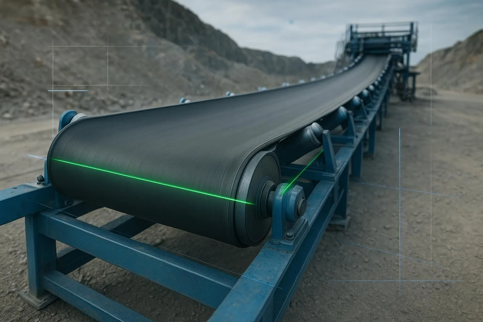
Start with the frame and pulleys. Establish a conveyor centerline with laser or piano wire. Square and level the tail, head, and all bend pulleys. Confirm take‑up alignment and travel. Next, set all idler frames perpendicular to the belt line and centered; shim as needed and record shim stacks. Verify transition distances against design. Only when the conveyor is geometrically correct should you install training devices.
Tensioning comes next. Commission with staged loading. Confirm take‑up position and belt sag within your design’s expectations, and compare power draw to design to detect abnormal drag from seized or misaligned rolls. If you must steer, start in the low‑tension zones—usually the return run before the tail.
Trainer selection and placement need discipline. Public CEMA committee materials summarizing Appendix D guidance advise placing trainers at least about 50 ft (15 m) from terminal or bend pulleys, typically spaced near 100 ft (31 m), staying out of transitions, high‑tension zones, and vertical curves. For one‑direction conveyors, start with one trainer on the return run prior to the tail; for reversing systems, use reversing trainers at mid‑span or per device design. See CEMA’s public committee agenda set describing these themes: CEMA Accessories Committee 2019 agenda set.
Pulley/lagging choices matter. Use flat‑faced drive pulleys on high‑tension systems; reserve crowns for light, low‑tension sections where appropriate. Select lagging to maintain consistent friction; clean and inspect it regularly.
Below is a compact comparison to help choose a tracking approach.
Sources for general context: Martin Engineering Foundations hub on tracking; CEMA Accessories Committee public agenda sets summarizing trainer placement themes.
Troubleshooting: a field‑proven workflow
When a belt starts to wander, diagnose upstream and make one change at a time. A practical sequence, echoed by industry guides, is: observe empty and then under load; clean carryback and return rolls; square pulleys and idlers; correct loading; then use trainer adjustments in small increments. Superior Industries’ tech tip lays out this upstream‑first logic and cautions against “training” with uneven take‑up turns: conveyor belt mistracking tech tip.
Use the “three revolutions” rule as you tune: after an adjustment, let the belt make at least three full revolutions before judging the effect. On troughed carry runs, adjust the preceding idler set slightly—only a few millimeters—on the side the belt needs to move toward. On the return run, pivot the trainer or a return roll bracket minimally and watch results upstream first.
Common root causes to confirm in order of leverage: off‑center loading (chute, skirt pressure), gross pulley misalignment, crooked splice, seized or dirty return idlers, contamination or uneven lagging friction, transition too short, take‑up skew, and structural drift (e.g., settling supports). For a stepwise, photo‑rich checklist, see BisonConvey’s practitioner guide: How to fix conveyor belt misalignment.
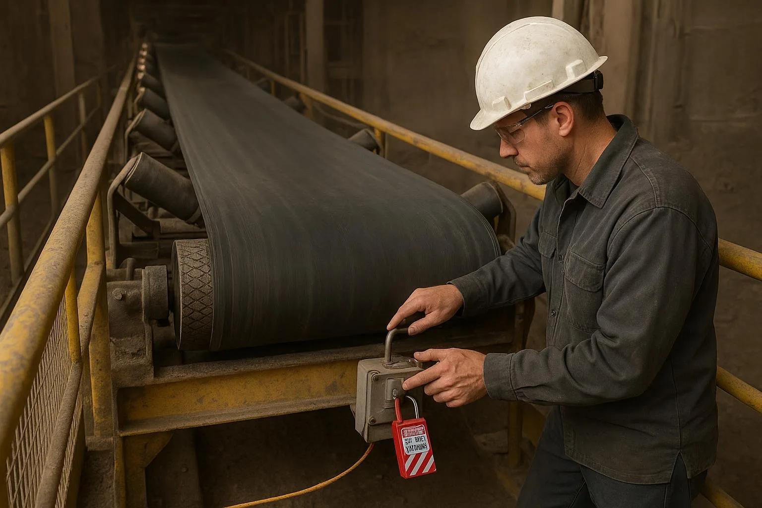
Safety note: Lockout/tagout, block from motion, relieve take‑up energy, and use engineered belt clamps before any hands‑on adjustment. MSHA’s Powered Haulage guidance consolidates these basics for conveyor work: MSHA Powered Haulage Guidance. For guarding and drive/transmission safety, reference OSHA 1910.212 and 1910.219: OSHA 1910.212 Machine Guarding and OSHA 1910.219 Mechanical Power‑Transmission Apparatus.
Best practices and maintenance
Make tracking part of routine reliability, not emergency response. Establish a cadence. During shift walkdowns, look and listen for drift, edge rub, unusual noise, and buildup on return rolls. Weekly, spot‑check idler rotation and temperature, verify take‑up position, and inspect cleaner and skirt contact. Monthly to quarterly, measure belt thickness and edge wear, audit lagging, and validate emergency stops. Trend power draw—rising power at fixed tonnage often signals drag from seized rolls or misalignment. For noise‑related diagnostics that often correlate with drift, see the practical primer: how to fix conveyor system noise.
Track a few KPIs so you can see problems early: belt drift at fixed reference stations (empty and loaded), trainer activity/interventions per 1,000 hours, edge wear rate, splice rework frequency, and spillage per 1,000 tons. A simple logbook (date, location, condition, adjustment, result) makes the “three revolutions” rule measurable instead of anecdotal.
Micro‑example: a neutral workflow with component upgrades
A plant feed conveyor with a textile belt showed steady right‑hand drift under load. The crew verified structure squareness with a laser and cleaned return rolls. They re‑centered the loading stream and set equal, modest skirt pressure. Several seized return idlers were replaced with sealed CEMA‑class‑appropriate units, and one self‑aligning return trainer was added about 60 ft before the tail—outside transitions and high‑tension zones—followed by incremental upstream idler tuning. The result was stable tracking across empty and loaded conditions. Component sourcing followed ISO belt scopes and common CEMA practices; a supplier like BisonConvey can provide belts, idlers, and pulleys specified to those standards.
Standards and references (public, accessible)
-
Trainer placement and installation themes consistent with Appendix D of the CEMA Belt Book: CEMA Accessories Committee 2019 agenda set and CEMA Accessories Committee 2022 agenda set.
-
ISO belt scopes/status (textile and steel‑cord belts): ISO 14890 catalogue entry and ISO 15236 series pages (see Parts 2/3 for scope/status notes).
-
Crowns and tracking context: Martin Engineering Foundations learning center.
-
Field workflow reference: Superior Industries mistracking tech tip.
Internal resources for further reading:
-
Theory background: Conveyor belt tracking theory — ultimate guide.
-
Idlers and why they matter: Belt conveyor idlers: definition and importance.
-
Visuals and splicing/transition notes: Rubber conveyor belt visual resources.
Conclusion: what to do next
Here’s the deal: tracking that stays fixed starts with geometry and loading, not gadgets. If you take one thing from this Comprehensive guide to conveyor belt tracking, make it this sequence—align, center, clean, then train sparingly. Use flat‑faced pulleys on heavy‑duty drives, reserve crowns for light duty, and place trainers where they can work without fighting physics. Keep clean records, measure drift at reference points, and review your KPIs monthly.
If you need help selecting CEMA‑class idlers, specifying pulleys and lagging, or verifying alignment against ISO belt scopes for your duty, our engineers at BisonConvey can review drawings and recommend component sets and checklists tailored to your system. It’s a straightforward way to reduce downtime and keep the belt where it belongs—on center.
About the author
A senior mechanical engineer specializing in bulk material handling with 15+ years commissioning and troubleshooting conveyors across mining, cement, and ports. Focus areas include installation QA, tracking and cleaning systems, and lifecycle reliability.