Steel Cord Conveyor Belt Splicing — The Ultimate Engineer’s Guide
Steel cord conveyor belt splicing is where reliability is won or lost. A splice that looks fine on day one can become the weakest link under dynamic loading, bending over pulleys, moisture, heat cycles, and impact. This guide gives you a field‑tested, standards‑aware playbook for planning, executing, and inspecting hot vulcanized stepped splices, and for deciding when cold or mechanical options make sense. All numeric ranges are typical and indicative—always follow your belt and splice‑kit manufacturer’s manuals and safety procedures.
Safety note: Splicing should be performed only by trained technicians under a documented lockout/tagout and hot‑work program. Use engineered clamps and verify zero motion.
Key takeaways
-
Steel cord conveyor belt splicing is best done by hot vulcanization for long‑term strength and fatigue life; cold and mechanical options are limited‑use.
-
Splice performance depends on geometry (step count/length, cord pitch/diameter), cord‑to‑rubber adhesion, uniform curing, and correct pulley diameters.
-
Use ISO 15236 (family) and ISO 7623 (adhesion test) for context, with DIN 22131 for belt designation/performance; use CEMA for safe work practices.
-
Control temperature, pressure, time, and cooling under pressure; document cure logs and inspect with visual criteria and, for critical conveyors, NDT scans.
What is Steel Cord Conveyor Belt Splicing?
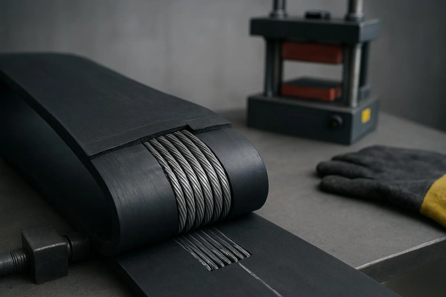
Steel cord conveyor belt splicing joins two belt ends so they act as a single, continuous tension member. In steel cord belts, longitudinal steel cables (cords) carry the load, embedded in core rubber and protected by top/bottom cover rubber. Key terms you’ll see:
-
ST rating: belt tensile rating per width (e.g., ST 3150). Defines strength class and informs step count and pulley sizing.
-
Cord diameter and pitch: the wire rope size and center‑to‑center spacing. These drive minimum step length and rubber spacing rules.
-
Step splice: staggered “steps” that overlap cord groups so load transfers gradually across the joint.
-
Splice efficiency and fatigue life: not just static strength—dynamic bending and stress distribution over millions of cycles matter most.
Hot vulcanized splicing is the default choice for steel cord conveyor belt splicing because it produces a homogeneous rubber matrix across the joint. According to the standards landscape summarized by ConveyorBeltGuide, steel‑cord splice patterns and practices are referenced in ISO standards and manufacturer manuals, while belt designation/performance is captured in DIN 22131 and ISO 15236 family documents. See the standards section below for links and roles.
Standards you should know
When you design and approve steel cord conveyor belt splicing, reference standards for terminology, performance context, and testing. Full texts are paywalled; we link to authoritative summaries and manufacturer literature for clarity.
-
ISO 15236 (family): defines steel cord belt construction and performance; Part 4 discusses vulcanized joints and simple pattern types. See ISO’s listing for Part 4 and recognized summaries. Source: ISO and ConveyorBeltGuide.
-
ISO 7623: specifies cord‑to‑coating (rubber) adhesion test methods—highly relevant to splice durability. Source: ISO index and standards overviews.
-
DIN 22131: covers belt designation and minimum performance for steel cord belts; practitioners still rely on belt‑maker splice manuals for geometry details. Source: ConveyorBeltGuide and manufacturer catalogues.
-
CEMA: provides conveyor design and safety context (e.g., lockout/tagout, belt blocking) rather than splice geometry. Source: CEMA safety notes and recognized safety guides.
Table — Standards at a glance (scope and how each relates to splicing)
Sources: ISO listing for Part 4 of ISO 15236 (2024) and ISO 7623 index; ConveyorBeltGuide standards overview and splice resources; Sempertrans catalogue confirmations of DIN/ISO alignment. Examples include: ISO’s Part 4 page, ConveyorBeltGuide’s splice patterns page, and Sempertrans Product Catalogue (2019).
-
ISO 15236‑4 listing at ISO.org: see the official index for Part 4: Vulcanized joints: https://www.iso.org/standard/92495.html
-
ConveyorBeltGuide standards and splice resources: https://www.conveyorbeltguide.com/st-splices.html
-
DIN/ISO performance context in Sempertrans Product Catalogue (2019): https://conveyor-belts.semperitgroup.com/fileadmin/user_upload/MediaLibrary/ConveyorBelts/Media/Downloads/Sempertrans_Product_catalogue_Nov_2019_EN.pdf
Splice design fundamentals (geometry, bending, and fatigue)
For steel cord conveyor belt splicing, geometry determines how load transfers across cords and how the joint survives bending. Industry‑shared rules of thumb provide a defensible starting point, but you must confirm final geometry with your belt supplier.
-
Step patterns: ISO 15236‑4 describes simple patterns (e.g., fir tree, organ pipe, finger) primarily for belts with higher safety factors. Modern manufacturer manuals often use optimized multi‑step patterns for high‑ST belts.
-
Indicative step counts by ST rating: published practice suggests roughly 1 step up to ST 2000; 2 steps for ST 2500–3150; 3 steps for ST 3500–4500; 4 steps for ST 5000–7500; and 5 steps for ST 7800–10000. Treat these as starting points only.
-
Minimum step length and rubber spacing: a typical rule is step length ≥ 100 × cord diameter; inter‑cord rubber width ≥ 2 mm or 0.3 × cord diameter, whichever is greater.
-
Cord pitch and diameter: larger diameters push minimum step lengths up; tighter pitch reduces available rubber and may limit feasible step counts.
-
Bending and fatigue: smaller pulleys increase bending strain; splice life is often fatigue‑limited, not static‑strength‑limited. Designing to spread stress and respect minimum pulley diameters greatly improves service life.
Evidence and reading:
-
ConveyorBeltGuide’s “Steel Cord Conveyor Belt Splice Patterns” summarizes the rules of thumb and pattern context: https://www.conveyorbeltguide.com/st-splices.html
-
A classic fatigue‑based view of belt and splice life is presented in “Steel Cord Belt and Splice Construction” (1993), emphasizing that dynamic behavior governs life: https://cvdyn.com/wp-content/uploads/2020/01/Steel-Cord-Belt-and-Splice-Construction-1993.pdf
Geometry cheat sheet (indicative; confirm with supplier manuals)
Hot vulcanized splice procedure (field‑proven overview)
This overview is practical but non‑proprietary. Always follow the belt/splice‑kit manufacturer’s detailed steps and datasheets.
Pre‑job safety checklist (jurisdiction‑agnostic)
-
Lockout/tagout energy sources, apply engineered belt clamps, and verify zero motion by attempt‑to‑start per recognized guidance (e.g., CEMA LOTO notes and OSHA 1910.147 in the U.S.).
-
Obtain hot‑work permits where applicable; clear combustibles; station a fire watch as required by policy.
-
Establish exclusion zones and communication; verify PPE and first‑aid/fire‑fighting gear.
Environment and tooling
- Prepare clean, dry, temperature‑controlled layup surfaces; mark centerlines and step offsets carefully. Verify press size covers the splice with margin and that power capacity is sufficient. Use calibrated thermocouples and pressure gauges.
Layup and cure parameters (typical ranges; follow datasheets)
-
Temperature: many steel‑cord systems cure around 140–160 °C; a common setpoint is about 145 °C ± 5 °C, with timing started at setpoint.
-
Pressure: representative full‑cure pressure is ≥ 1.2 MPa (≈ 12 kg/cm² ≈ 176 psi). Some procedures ramp pressure through heat‑up to full pressure during cure.
-
Time: a practical planning figure is roughly 3 minutes per 1 mm of total belt thickness. Heavy belts often require multi‑hour cycles.
-
Cooling: cool the splice under pressure to a safe demolding temperature before releasing pressure (often around 80 °C; confirm with your kit).
Quality and documentation
- Record temperature, pressure, and time curves; note ambient temperature and humidity. Perform visual/dimensional checks for straightness, thickness profile, edge condition, and controlled squeeze‑out; trim after full cool.
Authoritative references you can cite to stakeholders:
-
Sempertrans steel‑cord splicing instructions (2023) for indicative parameters and process control emphasis: https://conveyor-belts.semperitgroup.com/fileadmin/user_upload/MediaLibrary/ConveyorBelts/Media/Downloads/Steelcord_Belt_Splicing_Instructions-EN-web.pdf
-
Continental service pages highlighting monitored process variables (temperature, pressure, time, ambient): https://www.continental-industry.com/kr/en/products-solutions/conveying-solutions/services-field-service/belt-splicing
-
Martin Engineering’s vulcanized splice overview for accessible background: https://foundations.martin-eng.com/knowledge/vulcanized-conveyor-belt-splices
-
OSHA 1910.147 and CEMA LOTO note for safety framework: https://www.osha.gov/laws-regs/regulations/standardnumber/1910/1910.147 and https://cemanet.org/wp-content/uploads/2018/05/LockOut-TagOut-2.pdf
Selection guide: hot vs. cold vs. mechanical
Decision‑makers balance uptime, skill/equipment availability, and risk. Hot vulcanized is the default for steel cord conveyor belt splicing; cold and mechanical are exceptions with trade‑offs.
Supporting sources: industry summaries and manufacturer manuals emphasize hot vulcanization for steel‑cord belts, with cold and mechanical as limited or temporary solutions. See Martin Engineering’s overview and manufacturer literature cited above.
QA, inspection, and NDT
Acceptance starts with what you can see and measure, and it improves with what you can scan. A robust QA program reduces rework and unplanned stoppages.
Visual/dimensional acceptance
-
Straightness and alignment across the belt width; no skew or twist.
-
Overall thickness profile within tolerance; no bumps/dips that disturb tracking or pulley passage.
-
Correct step geometry and cord positioning per the approved plan; no voids, blisters, or contamination; edges show controlled squeeze‑out only.
Adhesion framework and specialist testing
- ISO 7623 defines cord‑to‑coating adhesion tests; adhesion is a first‑order determinant of splice life. Where practicable, rely on kit certification and supplier QA that reference ISO 7623 methods: https://www.iso.org/ics/53.040.20.html
NDT options (consider for critical conveyors)
-
Ultrasound (UT): good depth resolution for internal defects; requires coupling, skill, and controlled conditions.
-
Infrared thermography (IR): fast, non‑contact screening for near‑surface issues; environment‑sensitive and less suited to deep defects.
-
Magnetic flux leakage (MFL): suited to steel‑cord belts for detecting broken cords, corrosion, and splice anomalies; requires dedicated systems and expertise.
Further reading: ConveyorBeltGuide’s monitoring and papers index outlines belt condition‑monitoring and NDT approaches: https://www.conveyorbeltguide.com/monitoring.html
Common problems and troubleshooting
Most splice failures trace back to geometry errors, contamination, or inadequate cure. Use the symptom‑cause‑action approach below to triage and prevent repeats.
Context: the fatigue‑based design lens from the 1993 paper above explains why geometry and bending conditions dominate life. Use it to justify proactive QA and periodic scans.
Maintenance and splice life (what to do after commissioning)
A strong splice still needs the right environment to live a long life. Focus your maintenance on smooth belt passage, even loading, and early detection.
-
Inspection intervals: build short‑interval inspections for the first weeks after commissioning; extend as confidence grows. Schedule periodic detailed checks for critical conveyors and after any overload or jam.
-
Idlers and impact: misaligned or seized idlers and poorly tuned impact beds load the splice unevenly. See your idler and impact systems and alignment program; if you need components, review your options for pulleys and idlers.
-
Pulleys and lagging: keep lagging in good condition and respect supplier‑approved minimum pulley diameters; don’t relocate a splice to a high‑curvature pulley without a risk review.
-
Tracking and tension: confirm tracking through transition zones and over the splice; re‑tension after run‑in per supplier guidance.
-
Event‑driven NDT: after suspected impacts, jams, or drive trips, plan a UT/MFL scan before returning to full load on high‑criticality lines.
Supporting evidence: Sempertrans catalogues discuss how cord diameter, breakers, and construction influence pulley diameters and fatigue; ConveyorBeltGuide’s engineering pages summarize pulley‑diameter implications. See Sempertrans Product Catalogue (2019): https://conveyor-belts.semperitgroup.com/fileadmin/user_upload/MediaLibrary/ConveyorBelts/Media/Downloads/Sempertrans_Product_catalogue_Nov_2019_EN.pdf
Worked example (indicative only)
Imagine you are planning a splice for an ST 3500 steel‑cord belt with cord diameter d and pitch p provided by the supplier, and a total belt thickness t.
-
Step count: the indicative table suggests a 3‑step pattern for ST 3500. You confirm feasibility with the supplier’s splice manual.
-
Minimum step length: you apply L ≥ 100 × d and verify that the resulting splice envelope fits within your press dimensions with adequate margin.
-
Rubber spacing: you check that inter‑cord rubber width is at least 2 mm or 0.3 × d, whichever is greater, given the pitch p.
-
Pulley diameters: you verify the minimum pulley diameters from the belt datasheet and confirm the splice will not repeatedly pass a high‑curvature pulley under peak load.
-
Cure plan: you set a nominal target of 145 °C ± 5 °C, ≥ 1.2 MPa, and roughly 3 minutes per mm of thickness t—then you replace these placeholders with the exact values from your belt and splice‑kit datasheets.
-
QA plan: you prepare a visual acceptance checklist and schedule a post‑commissioning MFL scan because the conveyor is critical to plant throughput.
These steps translate engineering principles into an approvable method statement while keeping authority with the supplier’s manuals and site safety procedures.
Conclusion and next steps
If you remember nothing else, remember this: splice geometry, adhesion, and controlled curing determine whether your steel cord conveyor belt splicing will last. Build your plan around standards‑aligned terminology (ISO 15236 family), adhesion expectations (ISO 7623 context), safe work practices (CEMA/OSHA), and meticulous QA. Document the cure, cool under pressure, inspect what you installed, and scan what you can’t see when the risk is high.
For component selection (idlers, pulleys) that supports long splice life or to discuss engineering considerations for your next shutdown, you can contact BisonConvey for a neutral review of options and custom component solutions.
References (selected, linked inline above)
-
ISO 15236‑4 listing (2024): Steel cord conveyor belts — Vulcanized joints: https://www.iso.org/standard/92495.html
-
ISO conveyor components index (incl. ISO 7623): https://www.iso.org/ics/53.040.20.html
-
ConveyorBeltGuide — Splice patterns/standards/monitoring: https://www.conveyorbeltguide.com/st-splices.html, https://www.conveyorbeltguide.com/monitoring.html
-
Sempertrans Product Catalogue (2019) and Splicing Instructions (2023): https://conveyor-belts.semperitgroup.com/fileadmin/user_upload/MediaLibrary/ConveyorBelts/Media/Downloads/Sempertrans_Product_catalogue_Nov_2019_EN.pdf, https://conveyor-belts.semperitgroup.com/fileadmin/user_upload/MediaLibrary/ConveyorBelts/Media/Downloads/Steelcord_Belt_Splicing_Instructions-EN-web.pdf
-
Continental belt splicing service/equipment (process control emphasis): https://www.continental-industry.com/kr/en/products-solutions/conveying-solutions/services-field-service/belt-splicing
-
Martin Engineering — Vulcanized splice overview: https://foundations.martin-eng.com/knowledge/vulcanized-conveyor-belt-splices
-
CEMA LOTO note and OSHA 1910.147: https://cemanet.org/wp-content/uploads/2018/05/LockOut-TagOut-2.pdf, https://www.osha.gov/laws-regs/regulations/standardnumber/1910/1910.147