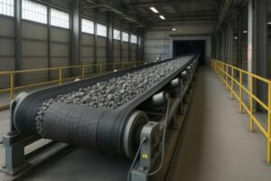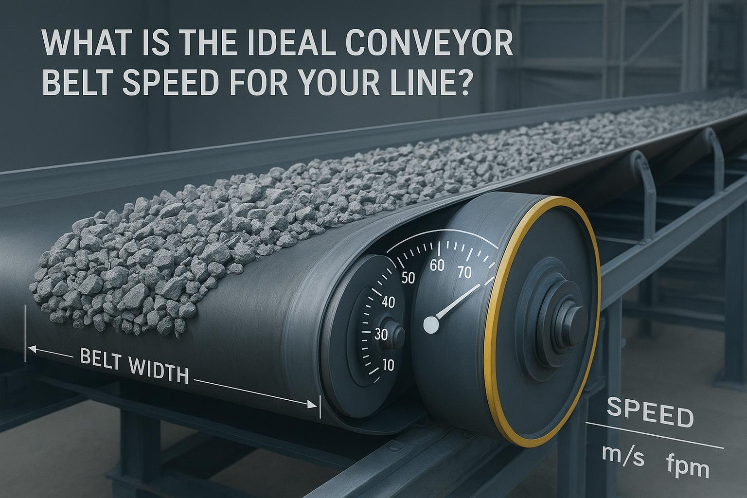
Ideal belt speed is the belt’s linear velocity that meets your required throughput while keeping dust, spillage, degradation, wear, noise, energy use, and control within acceptable limits and within component and standards constraints. In practice, “ideal” means a speed you can defend to operations and maintenance: stable loading and discharge, manageable fugitive material, and component life that aligns with your budget and uptime targets. Belt speed is expressed in meters per second (m/s) or feet per minute (fpm), and at the belt equals the tangential speed at the drive pulley’s circumference.
Why belt speed matters
Conveying capacity depends directly on speed. For bulk belts, the mass flow rate Q [t/h] is:
Q = A · v · ρ · 3600
- A: loaded cross-sectional area [m²] on the belt (a function of belt width, trough angle, surcharge angle, and filling ratio)
- v: belt speed [m/s]
- ρ: bulk density [t/m³]
Increase v and Q rises—up to the point where dust, spillage, impact, and component limits become unacceptable. Think of it like highway traffic: you can move more cars by increasing speed, but past a threshold you get more accidents and chaos. In conveyors, that “chaos” shows up as dust clouds at transfers, carryback, idler noise, and shortened component life.
Quick conversions between common units help:
| m/s | fpm |
|---|---|
| 1.0 | ≈ 196.85 |
| 2.5 | ≈ 492 |
| 5.0 | ≈ 984 |
| 7.5 | ≈ 1476 |
| 10.0 | ≈ 1969 |
The trade-off in one line: for many bulk systems, wider-and-slower often beats narrower-and-faster for the same throughput—lower dust, smoother transfers, and friendlier component loads.
How to calculate conveyor belt speed
The belt speed equals the tangential speed at the drive pulley:
v = π · D · N / 60
- v: belt speed [m/s]
- D: drive pulley diameter [m]
- N: drive pulley rotational speed [RPM]
Worked example (pulley-based):
- Assume D = 1.0 m and N = 180 RPM
- v = π · 1.0 · 180 / 60 = π · 3 ≈ 9.42 m/s (≈ 1859 fpm)
To convert directly to imperial:
- v [fpm] = π · D [ft] · N
If D = 3.28 ft and N = 180 RPM, v ≈ 3.1416 · 3.28 · 180 ≈ 1853 fpm (≈ 9.42 m/s).
From throughput to speed selection
Starting from required capacity, rearrange the mass flow formula:
v = Q / (A · ρ · 3600)
The challenge is estimating A, the cross-sectional area of the load. For troughed belts, A depends on belt width (e.g., 1000, 1200, 1400 mm), trough angle (20°, 35°, 45°), surcharge angle (material-dependent), and filling ratio. Engineers typically use CEMA-based tables to find A for given width and geometry.
Worked example (assumptions clearly noted):
- Target Q = 1000 t/h of crushed limestone
- Assume ρ = 1.6 t/m³
- Belt width = 1200 mm, trough angle 35°, surcharge angle 20°, filling ratio consistent with CEMA practice
- Representative loaded cross-sectional area A ≈ 0.14 m² (assumption for illustration only; use tables for exact value)
Then v = 1000 / (0.14 · 1.6 · 3600) ≈ 1.24 m/s (≈ 244 fpm)
If your tables show A is smaller for your geometry, required v rises; if A is larger (wider belt or higher fill), required v falls. This is why width and speed are coupled choices.
Standards and typical ranges by application
Standards and authoritative practice guide where “ideal” speeds tend to land:
-
General plant conveyors: Often 2–4 m/s (≈ 400–800 fpm). Common baseline around 2.5–3.0 m/s for stable transfers and manageable dust. This aligns with idler practice and discharge behavior discussed in manufacturer literature such as the PPI Idler Selection Guide.
-
Engineered high-speed bulk systems: Some modern belts run about 7.5–11.5 m/s (≈ 1400–2300 fpm) when designed for it, but these demand optimized chutes, sealing, and component selection. Martin Engineering highlights both the feasibility and pitfalls in “Ten Common Mistakes in Conveyor Specification & Design”.
-
Overland conveyors at very high speeds: With specialized design and dynamic analysis, 10–20 m/s systems are feasible. See the high-speed design considerations in Lodewijks’ paper, “The Design of High Speed Belt Conveyors”.
-
Weighing, ingredient, or inspection belts: Typically ≤1.25 m/s to preserve dwell time and measurement accuracy. Belt scales from leading manufacturers specify maximum speeds around 5 m/s for accuracy; see Siemens’ documentation, e.g., Milltronics belt scale guidelines. For ergonomics at manual workstations, many guidelines cap near 10 m/min (≈ 0.167 m/s); see CCOHS conveyor ergonomics.
-
Standards context: CEMA (Belt Conveyors for Bulk Materials), DIN 22101, and ISO 5048 provide calculation frameworks and design practices. While their detailed tables are paywalled, accessible overviews summarize methods—see ConveyorBeltGuide equations.
Constraints and trade-offs shaping “ideal” speed
Choosing speed isn’t only about hitting tonnage. It’s about controlling behavior at loading, transfers, and discharge while staying within component limits.
-
Dust and spillage: Faster belts entrain more air through chutes, liberate fines, and increase fugitives. Martin Engineering warns against substituting speed for width; wider-and-slower often achieves the same throughput with less dust. Practical guidance is outlined in Martin’s specification/design article and knowledge resources on fugitive material.
-
Idlers and dynamics: Speed increases roller RPM, noise, and bearing demands. Manufacturers publish limits and spacing guidance; consult the PPI Idler Selection Guide and match CEMA class to loading and speed.
-
Belt troughability and pulleys: Stronger belts may be stiffer; verify troughability at your chosen speed and ensure minimum pulley diameters and lagging types recommended by standards and suppliers. PPI’s Pulley Catalog offers dimensional and lagging context.
-
Cleaners and scales: Belt cleaners carry speed ratings (often around 4.3–5.1 m/s for some secondary models). Belt scales require speed caps for accuracy and proper idler spacing in the weighing area. Review Siemens Milltronics guidance and Martin cleaner datasheets such as SQC2 and DT2S.
-
Inclines and declines: Uphill conveyors may favor lower speeds for control; downhill (regenerative) systems demand brakes/holdbacks and often slower speeds to maintain stability. Beltcon papers summarize design considerations for downhill systems.
Component pairing checklist
Use this quick checklist to verify the chosen speed against component capability:
- Idlers: Match CEMA class, roll diameter, bearing quality, and spacing to the belt speed and load. Higher speeds may warrant larger rolls to reduce RPM and closer spacing in impact zones.
- Pulleys and lagging: Confirm minimum diameters for your belt rating and speed; choose lagging (ceramic, rubber) appropriate for traction and cleaner interaction.
- Belt cleaners and plows: Verify speed ratings and blade types; ensure tensioning systems suit the speed.
- Skirting and transfer design: Engineer chutes to control trajectory and deceleration; use sealing systems and settling zones to manage dust at higher speeds.
- Instrumentation: Check belt scales, metal detectors, and scanners for speed limits and dwell-time requirements.
Decision workflow and quick sizing examples
A simple way to structure belt speed selection:
- Define throughput and material properties (ρ, surcharge angle). Choose preliminary belt width and trough angle.
- Estimate cross-sectional area A from standards tables; compute required v = Q / (A · ρ · 3600).
- Stress-test the speed against constraints: loading/transfer behavior, dust, idler limits, pulley diameters, cleaner and scale ratings, incline/decline control.
- Iterate width vs speed: if speed is high and dust/control look marginal, consider a wider belt at a lower v.
- Lock in component specs and confirm drive power/tension per CEMA/DIN/ISO.
Quick examples (illustrative):
-
Pulley RPM → speed: D = 0.8 m, N = 120 RPM. v = π · 0.8 · 120 / 60 ≈ 5.03 m/s (≈ 991 fpm). If your plant prefers ≤3 m/s in transfer zones, you may need either a larger pulley or lower RPM via gearing/variable frequency drive.
-
Weighing/inspection dwell time: If an inspection camera requires 0.3 s dwell on a 200 mm object length, target v ≤ 0.67 m/s so the object remains under the camera long enough (200 mm / 0.3 s ≈ 0.67 m/s). Many weighing lines operate ≤1.25 m/s to preserve accuracy.
-
High-speed overland note: A long, straight overland conveyor moving stable ore may be engineered at 8–10 m/s with advanced transfer and dust control. Above ~10 m/s, dynamic analysis, precise alignment, and specialized components become essential; see Lodewijks’ discussion in high-speed conveyor design.
Example workflow (neutral disclosure)
Disclosure: BisonConvey is our product.
Consider 1000 t/h of crushed limestone, ρ ≈ 1.6 t/m³, trough angle 35°. Two paths:
- Option A: 1200 mm belt at ~3.0 m/s. Larger A reduces required v, typically yielding calmer transfers and lower dust. Idler spacing can remain within common plant practice; cleaner and scale speeds more likely within standard ratings.
- Option B: 1000 mm belt at ~3.6 m/s. Narrower belt requires higher v for the same Q, raising air entrainment through chutes and sensitivity to idler spacing and cleaner speed limits.
Both can be engineered successfully. The “ideal” choice depends on your dust control targets, transfer chute design, idler class, and instrumentation limits. BisonConvey supplies belts, idlers, and pulleys that can be specified to the selected speed and geometry; the engineering decision rests on your site constraints and life-cycle priorities.
Troubleshooting symptoms of “too fast” vs “too slow”
-
Signs of too fast: visible dust clouds at transfers; material ricocheting in chutes; increased carryback despite cleaner tensioning; idler noise and hot bearings; frequent spillage at loading points.
- Remedies: widen belt to lower v; upgrade chute design with controlled trajectories; add sealing and settling zones; validate cleaner speed ratings; adjust idler spacing/class.
-
Signs of too slow: poor discharge off head pulley; material buildup on skirt seals; inefficient capacity utilization; erratic scale readings due to insufficient dwell mass.
- Remedies: increase v to meet minimum discharge behavior; adjust chute geometry; verify scale placement and idler alignment; consider narrower belt with appropriate speed if space/power allow.
FAQs
How fast can a conveyor run?
Engineered bulk systems routinely operate around 2–4 m/s in plants. With specialized design, some systems run 7.5–11.5 m/s, and high-speed overland designs may reach 10–20 m/s. Above roughly 10 m/s, design becomes specialized with dynamic analysis and advanced dust/transfer control; see Lodewijks’ high-speed paper.
What is a good conveyor belt speed?
“Good” depends on your application. For many bulk plant conveyors, 2.5–3.0 m/s balances capacity and control. For weighing or inspection, ≤1.25 m/s is common. If you’re chasing high tonnage, consider wider-and-slower before pushing speed, to minimize dust and wear.
How do I calculate belt speed for required TPH?
Use v = Q / (A · ρ · 3600). Determine A from standards tables based on belt width and trough geometry, and ρ from your material data. Then verify the resulting v against dust, idler, pulley, cleaner, scale, and incline constraints.
Is faster always better?
No. Faster increases capacity—but also dust, impact, noise, and component stress. Many sites achieve lower lifecycle cost by using a wider belt at lower speed to hit the same throughput.
References
- Martin Engineering — Ten Common Mistakes in Conveyor Specification & Design: industry practice and pitfalls
- PPI — Idler Selection Guide: speed-related limits and spacing
- PPI — Pulley Catalog: diameter and lagging context
- Lodewijks — The Design of High Speed Belt Conveyors: high-speed feasibility and design
- ConveyorBeltGuide — Equations overview: belt equations and standards references
- Siemens — Milltronics belt scale guidelines: accuracy and max speed
- CCOHS — Conveyor ergonomics: human-paced speed guidance
Next steps: If you want an engineering check of your belt width, trough geometry, and conveyor belt speed selection, share your capacity, material data, and layout. We’ll respond with a neutral sizing note and component compatibility review aligned to CEMA/DIN/ISO practice.