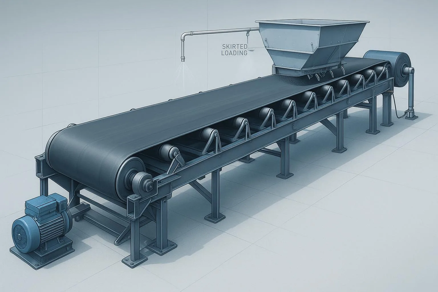
Plant reliability lives or dies on details like idlers. These non‑powered rollers carry, shape, and guide the belt day after day—quietly determining energy draw, spillage, tracking stability, and belt life. Get them right and you bank uptime; get them wrong and you inherit heat, noise, edge wear, and chronic mis‑tracking.
Key takeaways
-
Idlers are non‑powered rollers or roller sets that support and guide the belt on both carrying and return runs, shaping the cross‑section and influencing tracking and energy.
-
The most common types are troughing, impact, return (flat, V‑return, rubber‑disc), and self‑aligning/training; garland sets appear in certain applications.
-
Typical troughing angles are 15°–40° (sometimes 45°). Steeper angles raise capacity/containment but demand longer transition distances.
-
Carrying‑side spacing is engineered to keep belt sag about 1.5–2.0% of the idler span; return spacing is longer but must control flutter.
-
Selection is driven by belt width/speed, material, impact energy, CEMA class, roll diameter, sealing/bearing design, and environment—validated against manufacturer data and standards.
Formal definition and scope (with standards context)
In belt conveyors, idlers are the non‑driven rollers or roller assemblies that support and guide the belt along the carrying and return runs. On the carry side they form a trough so bulk material rides stably; on the return they support the empty belt and help control tracking. This scope and terminology align with CEMA Standard No. 502 on bulk belt conveyor troughing and return idlers, which organizes idlers by type and class for selection and dimensional interchangeability. See the publications overview at the CEMA site in the CEMA publications catalog. For power/tension context, ISO 5048 sets methods for calculating drive power and belt tensile forces for conveyors with carrying idlers; see the ISO 5048 listing. Dimensions for impact rings/discs are addressed historically in ISO 4123 within the ISO ICS 53.040.20 index. Always verify the latest editions directly on cemanet.org and iso.org before specification.
Core concepts and technical explanation
Anatomy of an idler set
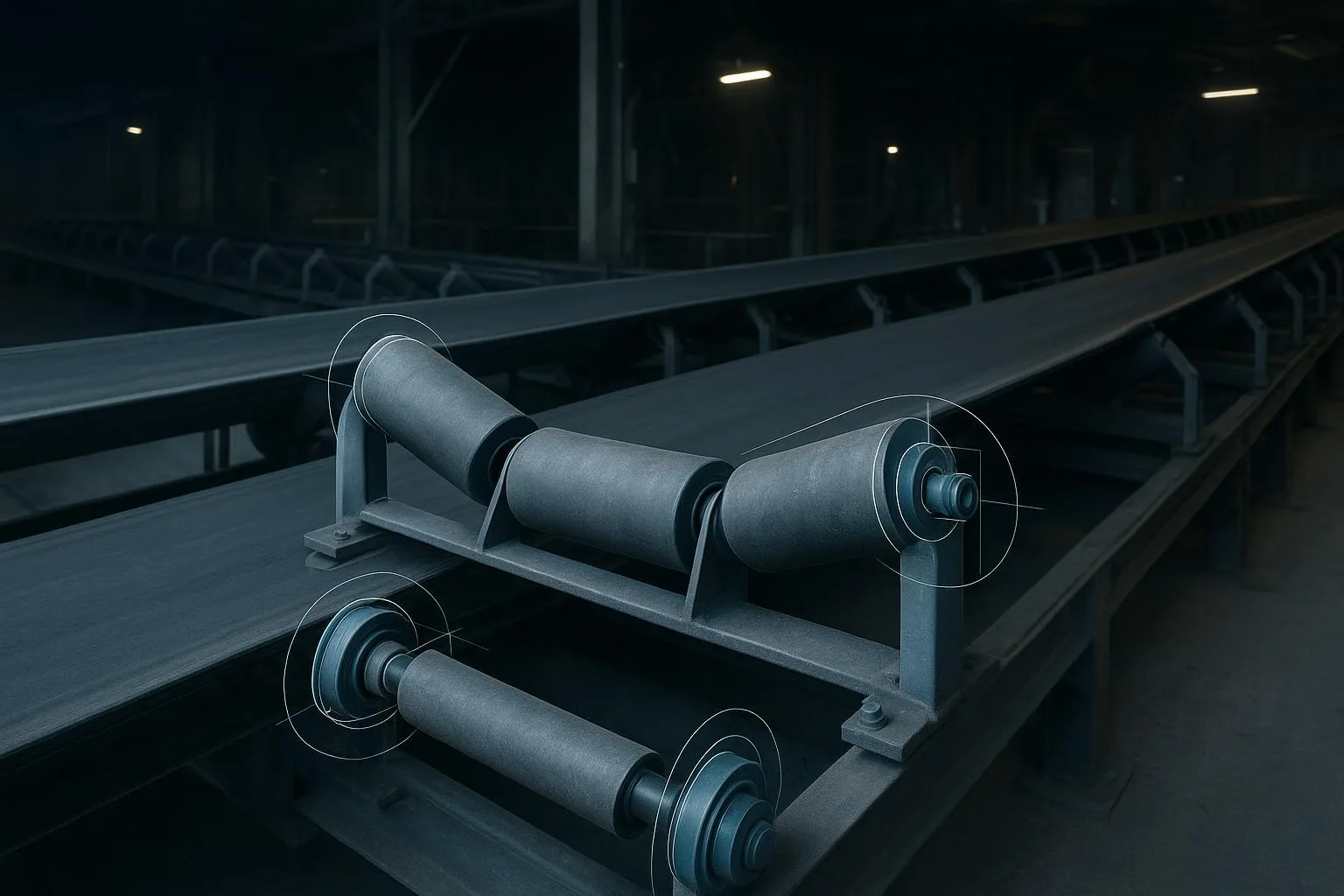
A typical carry‑side troughing set includes a steel frame and three rolls (left, center, right) with precision shafts, sealed deep‑groove ball bearings, and multi‑stage seals (labyrinth plus contact elements). Return idlers are generally single‑roll units (flat) or paired for V‑return. Critical quality levers include total indicated runout (TIR), bearing life (L10), seal design vs. drag, and frame alignment.
Troughing angles and their effects
Common equal‑trough angles are 15°, 20°, 25°, 30°, 35°, and 40°; some systems use 45°. Increasing angle raises the loaded cross‑sectional area at a given speed, improving volumetric capacity and material containment. However, steeper angles concentrate stresses at the belt edges if transitions are too short. Practical rules many OEMs teach: plan transition distances on the carry run near 1× belt width (BW) for ~20°, ~1.5× BW for ~35°, and ~2× BW for ~45°. See the geometry context in the Bulk‑Online technical paper on transition design: transition geometry notes. Manufacturer guides such as PPI’s idler selection materials also summarize angle availability and use patterns; see the PPI Idler Selection Guide.
Idler spacing, belt sag, and return stability
Engineers often begin with carry‑side spacing around 4 ft (≈1.2 m) and return spacing 8–10 ft (≈2.4–3.0 m), then adjust to limit belt sag and control tracking. A typical design target is 1.5–2.0% sag on the carry run, with an upper bound near 2% to protect splices and avoid material agitation. OEM selection manuals and power‑resistance methods reflect these norms; see the PPI CDP user manual defaults and spacing notes and the belt‑scale white paper discussing a 2% sag condition: Bulk‑Online belt scale accuracy note. On the return, V‑return idlers at 10°–15° help stabilize wide or fast belts and reduce flutter. Always confirm final spacings against calculated tensions, belt stiffness (troughability), and environmental load (moisture, carryback).
Types of idlers and where they fit
According to manufacturer references, selection and dimensions track closely to CEMA 502 classes; for a representative catalog see the PPI idler catalog (CEMA‑aligned).
Conveyor idler selection guide (what to specify)
When preparing RFQs or internal specs, organize inputs and decisions as follows:
-
Application inputs
- Belt width and speed; design capacity; material bulk density and surcharge angle; max lump size and drop height (impact energy); ambient temperature; dust/moisture; cleaning system.
-
Geometry choices
- Trough angle (15°–40° typical); transition distances from pulleys; carry and return spacing to hit ~1.5–2.0% sag; return style (flat vs. V‑return); use of trainers and their spacing.
-
Mechanical classing
- CEMA series (B, C, D, E, F, G) appropriate to loads; roll diameter and wall thickness; frame style and stiffness; runout and concentricity tolerances.
-
Bearings and seals
- Bearing series (e.g., 6203/6204 and up); target L10 life (commonly 30k–60k h depending on duty); seal stack (labyrinth + contact) chosen for contamination vs. drag trade‑off.
-
Environment and maintenance
- Corrosion protection, rubber disc options for return, taconite‑style sealing where needed; access for inspection and safe replacement.
For a step‑by‑step manufacturer viewpoint, see the PPI Idler Selection Guide. For power/tension context and resistance components, consult CEMA’s method and independent summaries such as the Bulk‑Online article on the horsepower equation lineage: CEMA horsepower/resistance overview.
Bearings, seals, energy, and life
Most idler rolls use sealed deep‑groove ball bearings. Life is typically expressed as L10 (the point at which 90% of bearings are expected to survive). Seal systems often combine a low‑drag labyrinth to exclude coarse contaminants with a contact element (felt or elastomer) for fine dust. The trade‑off is straightforward: stronger contact seals improve exclusion but add drag and heat, which can shorten life if alignment isn’t precise. Good practice includes checking frame planarity and shimming to avoid bearing distortion. Representative OEM documentation discusses housing/shimming and alignment practices; see PPI bearing housing and shimming guidance.
Common problems and troubleshooting
Inspection, maintenance, and safety
-
Routine inspection cadence
-
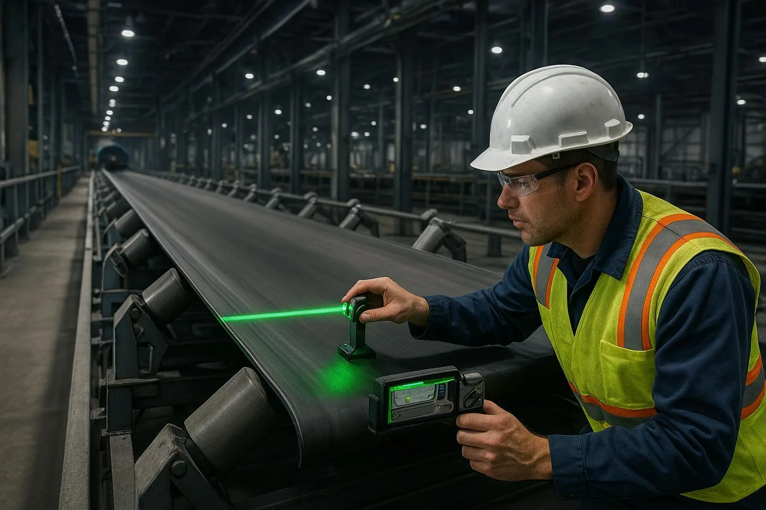
Walk the line for seized or noisy rolls; listen for tonal changes and feel for heat at housings.
-
Check fasteners and frame alignment; verify trainers are free to pivot and not over‑tightened.
-
Replace damaged seals/rolls promptly; chronic failures in one zone usually indicate root‑cause issues (loading, alignment, contamination).
-
-
Safety reminders
- Always lockout/tagout (LOTO) before servicing idlers; guard pinch points and rotating parts per OSHA/ANSI/CEMA guidance. For a practical overview, see this conveyor safety summary and consult OSHA 1910.212/1910.219 on guarding.
-
Documentation
- Record replacements and temperatures by location; trend noise/heat to anticipate bearing end of life.
Practical micro‑example (neutral, replicable)
A 1,200‑mm quarry conveyor running 35° equal‑trough idlers experienced edge wear near the head transition. The transition distance measured just under 1× belt width—short for 35°. We added an intermediate 20° set and extended the transition to ~1.5× BW. Edge wear subsided and tracking stabilized. On the return, switching a few standard rollers to rubber‑disc returns reduced carryback stripes. A supplier like BisonConvey, which offers belts, idlers, pulleys, and compatible frames, can provide CEMA‑rated troughers and rubber‑disc returns to match these changes. Engineers should still size by class, roll diameter, spacing targets, and environmental sealing.
Conclusion: what to remember and act on
-
Define idlers correctly: non‑powered rollers/sets that support, shape, and guide the belt on both runs.
-
Choose angles and transitions together: 20°–35° are common; 40°–45° demand longer transitions.
-
Design spacing to sag targets: aim ~1.5–2.0% on the carry run and control return flutter.
-
Specify class, roll diameter, bearings/seals, and tolerances per duty and environment; validate against CEMA tables and OEM data.
-
Maintain proactively with alignment, cleaning, and temperature/noise checks—always under LOTO and adequate guarding.
If you’re aligning specs across belts, idlers, and pulleys or considering an upgrade, discuss application details with BisonConvey’s engineering team to size the right CEMA‑rated components and sealing options for your site conditions.
SEO notes (for editors; not visible to readers):
-
Primary keyword used in H1 and H2s; long‑tails included naturally (what is an idler in belt conveyors, troughing idler angles, idler spacing and sag, self‑aligning idlers, impact idlers vs beds, conveyor idler selection guide, conveyor idler maintenance).
-
External links kept to authoritative sources: CEMA publications page, ISO 5048 listing, ISO ICS index, PPI guides/catalogs, Bulk‑Online technical paper, safety overview. Internal link to BisonConvey products page once.