History and Invention of the Conveyor Belt
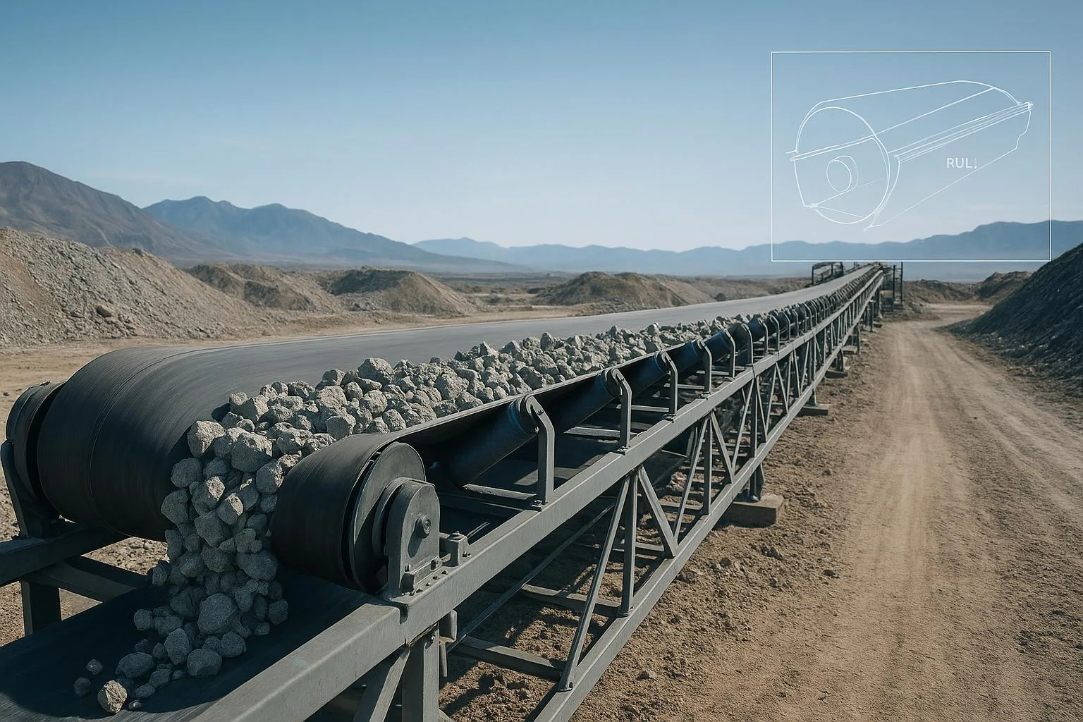
Conveyor technology is one of the quiet foundations of modern industry. Understanding the History and Invention of the Conveyor Belt isn’t just trivia—it explains why today’s belts, idlers, and pulleys look the way they do, which standards apply, and how to make better choices that reduce downtime. In this guide, I’ll combine a concise history timeline with practical, standards-based advice you can use in plants handling everything from ore and clinker to grain and unit loads.
Key takeaways
-
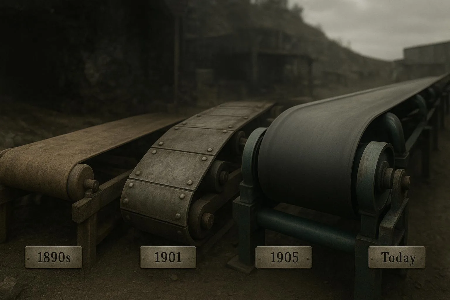
The core milestones—from 1890s prototypes to Sandvik’s steel belts in 1901, Sutcliffe’s mine conveyors in 1905, and Ford’s 1913 moving line—established the designs we still refine today.
-
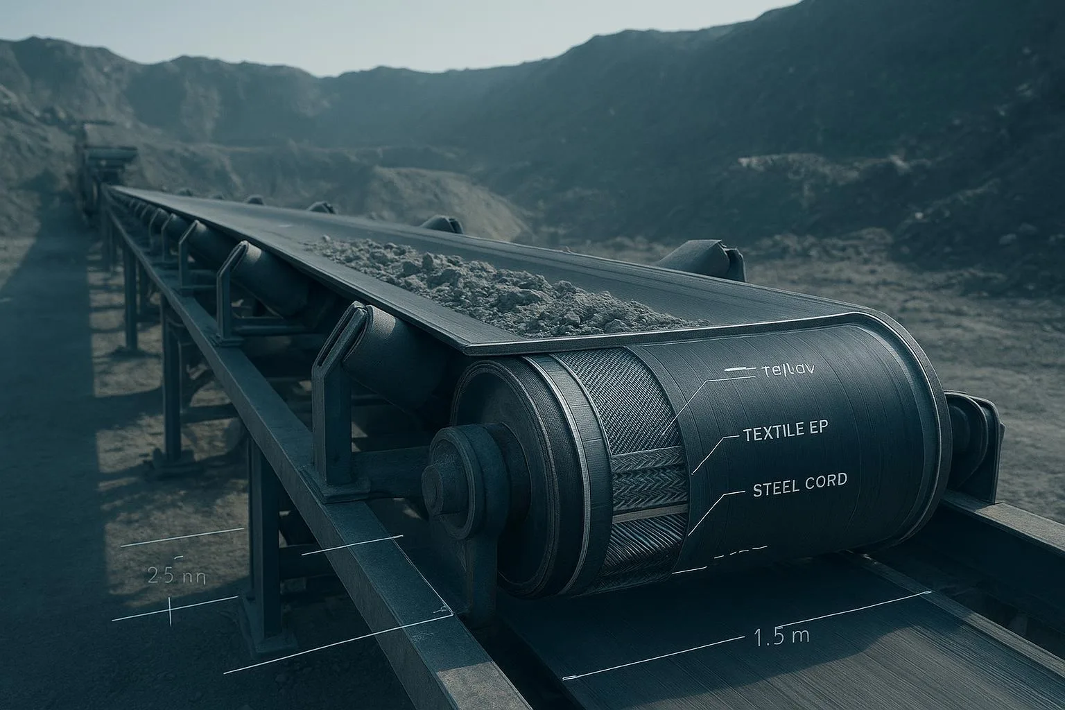
Modern selection hinges on carcass type (textile EP/NN vs steel-cord ST), cover compound, safety properties (flame, antistatic), and component sizing aligned to ISO and CEMA.
-
For heavy, long, or high-tension duties, steel-cord belts with engineered splices shine; for high-impact, tear-prone zones, textile belts often win.
-
Reliability comes from basics: correct pulley diameters and transitions, sound splicing, centered loading, effective cleaning, and disciplined inspection.
Conveyor belt history timeline
Who invented the conveyor belt? Attribution depends on which “first” you mean. Many secondary sources credit Thomas Robins—working with the Edison Ore-Milling Company in the early 1890s—with a heavy-duty belt system for ore handling. While these accounts are consistent, a definitive primary patent citation remains to be pinned down; several industry histories echo the Robins/Edison collaboration, including a widely referenced SEMCOR overview.
A documented industrial milestone arrived in 1901, when Sandvik began producing and delivering steel belts for conveyor installations. According to the company’s own record, the entry “Steel belts” appears under 1901 on the corporate history page. Some Sandvik publications note 1902 as the year the company started supplying steel conveyor belts, a minor discrepancy likely reflecting the difference between first production and scaled supply. See the company’s public history page for the 1901 entry and an anniversary magazine reference that cites 1902 for supply. These early steel belts were an inflection point for higher tensions and longer runs.
In underground coal mining, Richard Sutcliffe patented and introduced belt conveyors in 1905 in the UK, enabling continuous haulage at the face. The National Coal Mining Museum notes Sutcliffe’s 1905 patent and first installations that same year, a major step for safety and productivity in mines.
A separate stream of influence came from manufacturing: Henry Ford’s moving assembly line, introduced at Highland Park in 1913, reorganized factory flow around synchronized motion. The Library of Congress business history guide recounts the 1913 implementation and its dramatic impact on production time. While these were not bulk belts in the modern sense, the concept of controlled material flow on a moving surface leapt into mainstream industrial engineering.
From leather and canvas to vulcanized rubber, and then to textile and steel-cord carcasses with specialized covers (heat-, oil-, flame-, and antistatic-resistant), the 20th century was an evolution toward stronger, safer, more durable belts. Standards from ISO and design guidance from CEMA helped turn that evolution into predictable, interchangeable practice.
References (first mentions only):
-
Sandvik’s corporate history page on “Steel belts” (1901) and a later anniversary publication noting 1902 supply.
-
The National Coal Mining Museum’s note on Richard Sutcliffe’s 1905 patent and installations.
-
The Library of Congress guide describing Ford’s 1913 moving assembly line.
Core concepts and technical foundations
Belt construction basics
-
Carcass: The belt’s tensile body. Textile belts use multilayer fabrics—typically EP (polyester warp/nylon weft) or NN (nylon/nylon). Steel-cord belts embed longitudinal steel cords in rubber.
-
Covers: Rubber or plastics layers that shield the carcass from abrasion, heat, oil, chemicals, and weather. Compounds are selected for duty: abrasion grades, heat resistance, flame resistance, antistatic behavior, or oil/chemical resistance.
-
Ratings and notation: Textile belts are often denoted by total tensile rating and plies (e.g., EP 200/4), while steel cords use “ST” followed by nominal strength (e.g., ST2500). Strengths are expressed in N/mm.
-
Splicing: Mechanical fasteners enable quick joins but reduce strength and can increase wear. Vulcanized splices (hot/cold) are standard for heavy industry; steel-cord splices are engineered for cord layout and length to achieve high strength retention.
Components that shaped reliability
-
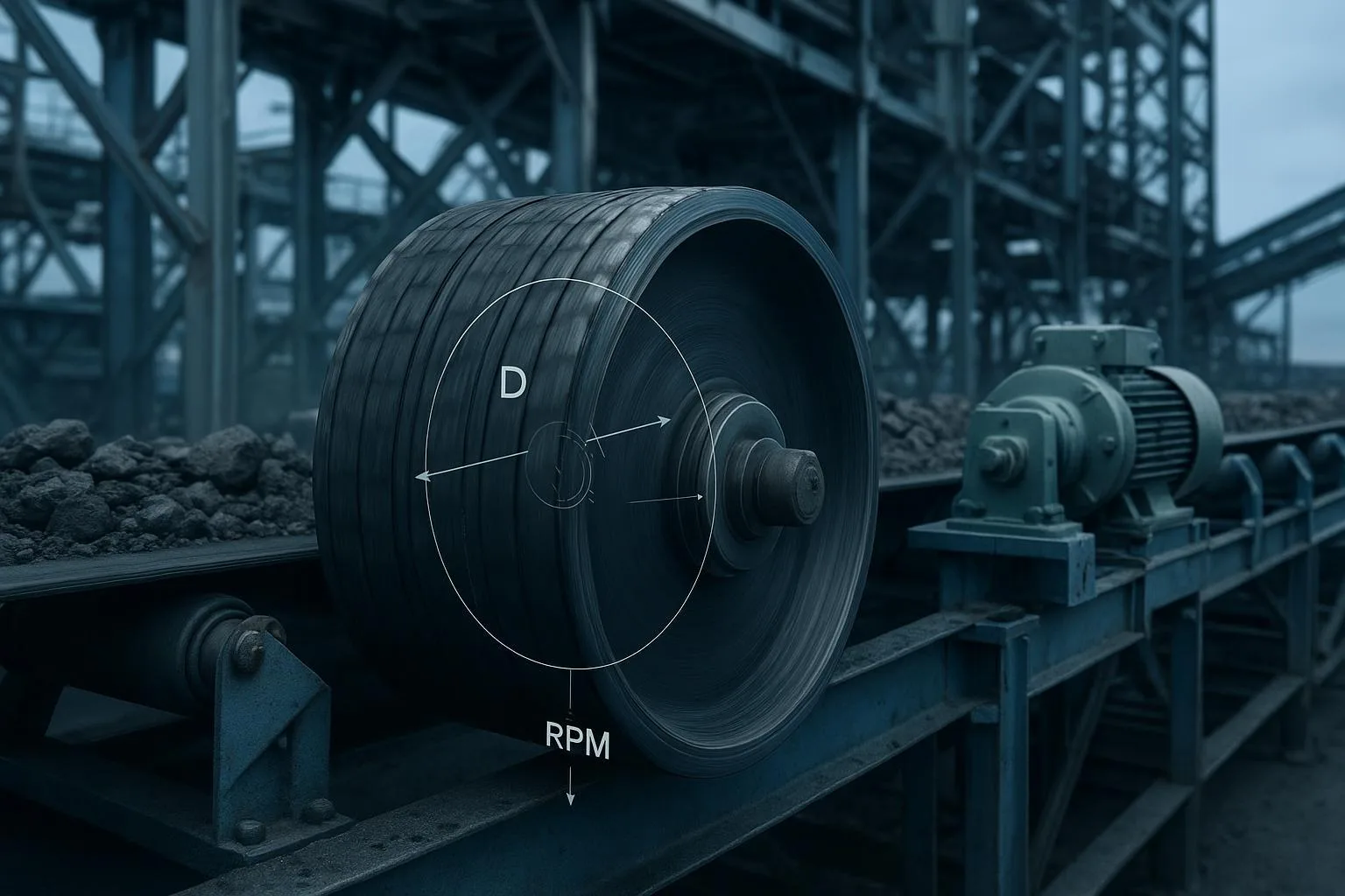
Pulleys: Drive, tail, bend, and snub pulleys set wrap angles and power transmission. Minimum pulley diameters depend on carcass and splice geometry—undersizing accelerates flex fatigue.
-
Idlers: Three-roll troughing idlers support the carry strand; return rollers support the return. Training idlers can nudge tracking, but they are not a substitute for sound alignment. Dimensional classes and load ratings are standardized in the industry; CEMA Standard 502 defines classes (B, C, D, E, F, and beyond) and interchanges used across North America and globally.
-
Take-up systems: Gravity or screw take-ups maintain working tension to prevent slip and accommodate elongation.
For a deeper primer on troughing idlers and why they matter to belt life, see the short explainer on belt conveyor idlers and their role in reliability: belt conveyor idlers definition and importance.
Safety and materials evolution (standards in practice)
-
ISO 14890 defines requirements for textile-construction belts with rubber/plastics covers for general surface use. While the full text is paywalled, the ISO Online Browsing Platform outlines scope and terminology used in specifications.
-
ISO 22721:2023 specifies principal characteristics for steel-cord belts in the 3150–10,000 N/mm range, guiding materials and performance definitions used by many OEMs and buyers.
-
ISO 340 addresses test methods for flammability of conveyor belts—often required in regulated environments.
-
ISO 284 defines requirements for electrical conductivity (antistatic), relevant in dust-prone or explosive atmospheres.
-
CEMA publications, including Standard 502 for idlers and the “Belt Conveyors for Bulk Materials” handbook, anchor design fundamentals, load ratings, and power/tension calculation methods used widely by designers and auditors.
Textile vs steel-cord at a glance
Applications and real-world examples
-
Mining and quarrying: Overland conveyors hauling ore or overburden often justify steel-cord belts (low elongation, stable tracking) and high-class idlers. In coal or gassy seams, select compounds conforming to flame resistance and antistatic requirements. Long transitions and correct pulley diameters are essential to prevent cord and splice fatigue.
-
Cement and building materials: Raw meal and clinker are harsh. Abrasion-resistant covers aligned with ISO 14890 cover classes help in raw handling, while heat-resistant compounds protect belts near the kiln or hot clinker conveyors. Where space forces steep angles, patterned covers can help.
-
Ports and logistics terminals: Shiploaders and stacker-reclaimers face weather, salt, and dust. Choose idlers with robust sealing and bearings appropriate for coastal exposure, and plan maintenance windows around vessel schedules. Good cleaning reduces carryback that would otherwise foul return idlers and pulleys.
-
Discrete manufacturing: Ford’s 1913 line popularized synchronized motion. Today’s plants mix belt and roller conveyors, with modular plastics for hygiene or ergonomic reasons in sub-systems, while bulk in-feed or waste lines still rely on textile or steel-cord belts sized per ISO and CEMA guidance.
Selection and implementation guidelines
Choosing between textile and steel cord
Think in terms of tension, length, loading, and maintenance envelope:
-
Use textile (EP/NN) when the conveyor is short-to-medium length, the take-up travel is sufficient to handle higher elongation, impact is severe, and rapid field repairs may be necessary near crushers or transfer points.
-
Choose steel-cord (ST) for long or high-tension routes where low elongation stabilizes tracking and minimizes take-up travel; design splices carefully and control bending cycles with correct pulley diameters.
Covers and compounds by duty
-
Abrasion: Align with ISO 14890 concepts (often mapped in practice to traditional DIN X/Y/W or ISO H/D/L descriptions in vendor literature). Observe the wear mode—sliding abrasion in chutes versus gouging at impact points—to select the right formula.
-
Heat and oil: For hot clinker, select heat-resistant compounds rated above your worst-case material temperature; for oils/fats/solvents, choose oil- or chemical-resistant covers to prevent swelling and softening.
-
Safety properties: Where regulations or risk assessments demand it, specify flame resistance per ISO 340 and antistatic behavior per ISO 284. Underground or ATEX-classified areas may require additional certifications.
Pulleys, diameters, and transitions
Minimum pulley diameters depend on belt construction, tensile rating, and splice geometry. Undersized pulleys raise flexural stress, leading to early carcass and splice failures. For preliminary checks and DIN-based guidance, use the Pulley Diameter Calculator to sanity-check minimums and iterate early in layout: pulley diameter calculator for DIN-based minima.
Transitions between flat pulleys and troughing idlers must meet the belt’s troughability. Too-short transitions pinch or crease the edges; too-long transitions can cause cupping. Align transition distance with belt width, carcass stiffness, and trough angle, referring to manufacturer charts during detailed design.
Orientation to power/tension (a quick, non-proprietary example)
Designers often start with the CEMA simplified method to estimate effective tension and power. Without reproducing proprietary tables, here’s a compact orientation:
-
Define material rate, belt speed, and conveyor length. Estimate the running resistance per unit length based on idler class, loading, and environment.
-
Compute effective tension Te as the sum of resistances for carrying strand, return strand, elevation changes, and special devices (cleaners, plows). Then determine tight-side and slack-side tensions (T1, T2) based on wrap angle and friction at the drive.
-
Example: Suppose a 1000 t/h conveyor at 2.5 m/s over 400 m with moderate rolling resistance. If your preliminary running resistance yields Te ≈ 45 kN, with a drive wrap and friction that give a permissible T1/T2 ratio of ~2.8, you might target T1 ≈ 63 kN and T2 ≈ 22.5 kN. Select a belt rating and width that provide adequate safety factor over T1, then verify take-up and motor power with detailed calculations and manufacturer data.
When you want to iterate quickly with plant-specific numbers, a simplified calculator can help frame discussions before full design. Try the conveyor belt tension calculator using CEMA concepts to scope motor and belt rating ranges for feasibility checks.
Common problems and troubleshooting
Mistracking is a symptom, not a root cause. Common drivers include out-of-square or twisted splices, off-center or segregated loading, frame misalignment, and buildup on idlers or pulleys. Rather than adding more training idlers, square the splice, correct the loading geometry, clean the return, and confirm idlers are aligned and freely rotating. Training devices are fine-tuning tools, not magic wands.
Premature cover wear often traces to carryback, abrasive chute geometry, seized idlers, or incorrect pulley choices that over-flex the belt. Multi-stage belt cleaning, proper wear liners and skirt settings, and right-sized pulleys reduce wear dramatically. If heat or oils are present, choose compounds designed for those exposures; otherwise the cover hardens, cracks, or swells and fails early.
Carcass failures—ply separations, cord breaks, or edge fraying—typically indicate one or more of: undersized pulleys, too-short transitions, chronic over-tensioning, or splices that were poorly designed or executed. Audit these basics first. In impact zones, consider impact beds or slider cradles to distribute loads and prevent localized damage.
Fire and static hazards require the correct compound and tests up front. In coal handling, power plants, or dust-prone processes, skipping flame-resistant or antistatic specifications is a risk no safety review will accept. Align with ISO 340 and ISO 284, and with your jurisdiction’s overlays for underground or hazardous areas.
Best practices and maintenance
Inspection discipline keeps the physics on your side. Rotate through daily operator walkdowns, weekly condition checks, and monthly deeper inspections focused on high-risk zones (loading, transitions, drives). Listen for bearing noise and feel for heat at idlers near the loading point; small temperature rises often precede seizure. Cleaners should be adjusted when carryback appears, not after piles grow.
Spare strategy matters: keep critical troughing and return idlers for your dominant belt width, and, where justified, a spare pulley or at least lagging kits and a documented change-out procedure. Maintain a splice kit matched to your belt family and have your splice procedure and QA checklist at hand.
Here’s a short, field-proven maintenance cadence you can adapt:
-
Keep the loading zone clean and centered; adjust skirts and maintain liners to eliminate plow-like material accumulations.
-
Verify idler alignment and rotation; replace seized or misaligned assemblies immediately.
-
Reconfirm splice integrity and squareness during every planned outage; log measurements to spot drift early.
Conclusion and next steps on the History and Invention of the Conveyor Belt
The History and Invention of the Conveyor Belt explains why today’s choices work: carcass type, cover compound, pulley diameters, idler classes, and safety properties all trace back to milestones like Sandvik’s early steel belts and Sutcliffe’s mine conveyors, then matured under ISO and CEMA guidance. When you apply those lessons—correct selection, careful splicing, centered loading, proper cleaning, and disciplined inspection—you get stable operation and fewer surprises.
If you’re scoping a new line or auditing an existing one and want pragmatic, standards-aligned options for belts, idlers, and pulleys, you can consult with BisonConvey for component options and engineering guidance tailored to your duty.
Sources and standards cited in-text:
-
Sandvik corporate history page for 1901 steel belts and a later publication that cites 1902 supply, offering context on the 1901/1902 variance.
-
The National Coal Mining Museum reference to Richard Sutcliffe’s 1905 patent and implementations in UK coal mining.
-
The Library of Congress guide detailing Ford’s 1913 moving assembly line and its impact.
-
ISO committee portal outlining scopes for textile belts, steel-cord belts, flammability, and antistatic behavior (single committee link retained for density control).
-
CEMA publications index for Standard 502 (idler classes) and the Belt Conveyors for Bulk Materials handbook.
External links (first mention only):
-
According to Sandvik’s corporate history, see the entry on steel belts in 1901: Sandvik history — steel belts and the later publication noting 1902 supply: Meet Sandvik magazine 2012-1 (PDF).
-
The Library of Congress summarizes the 1913 moving assembly line: LOC business history guide on Ford’s 1913 line.
-
The National Coal Mining Museum notes Sutcliffe’s 1905 patent and first installations: National Coal Mining Museum — Innovation Day.
-
ISO standards landscape and committee: ISO/TC 41/SC 3 — Conveyor belts.
-
CEMA publications and Standard 502 overview: CEMA publications index.
Internal links retained (≤3/1000 words):
-
Idlers explainer: belt conveyor idlers definition and importance.
-
Pulley Diameter Calculator: pulley diameter calculator for DIN-based minima.
-
Belt Tension Calculator: conveyor belt tension calculator using CEMA concepts.