
How to calculate conveyor belt RPM
Engineer‑grade guide to calculating conveyor belt RPM with formulas, unit conversions, gearbox & slip corrections, worked examples, and troubleshooting. Learn more.
If you work on bulk handling or manufacturing lines, sooner or later you have to convert between belt speed and drive pulley RPM. Getting that number right is more than math—it determines throughput, wear, power draw, and even dust behavior. This guide shows exactly how to calculate conveyor belt RPM (and the reverse), account for gearboxes and slip, and verify results safely in the field.
A quick scope note: the RPM–speed relationship comes from first‑principles kinematics. Standards like CEMA and ISO treat belt speed as a fundamental parameter in power/tension and testing; we’ll cite those publishers for context while keeping the math transparent.
Key takeaways
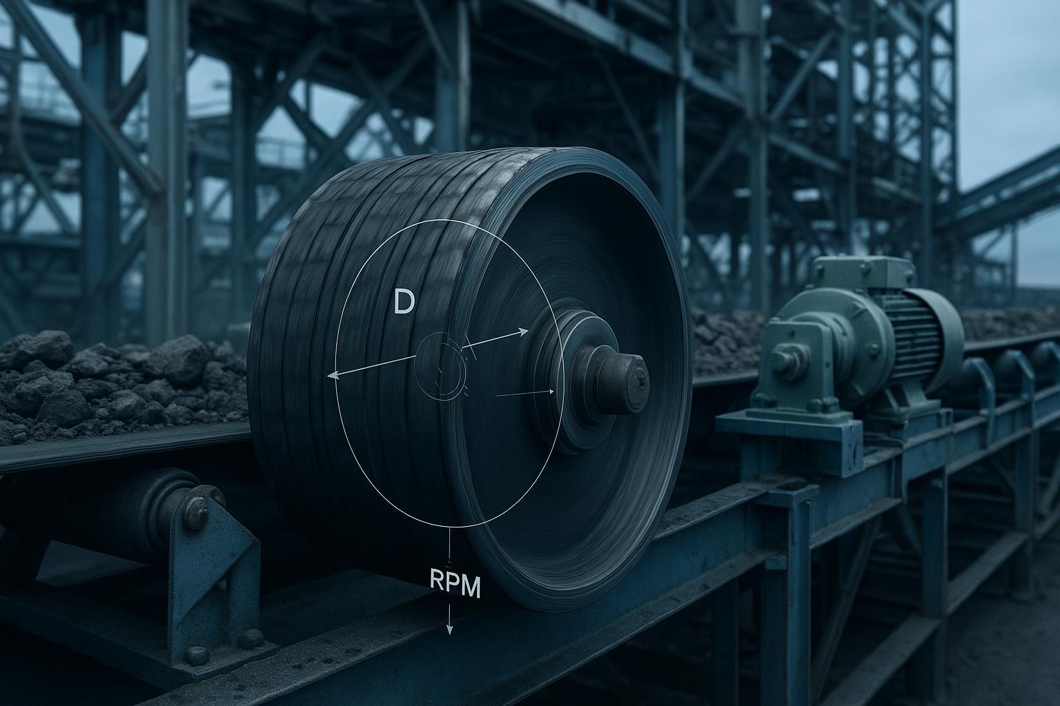
The governing relationship is v = (π × D × RPM)/60, where v is belt speed (m/s) and D is effective pulley diameter (m). In imperial units: V_fpm = (π × D_in × RPM)/12.
Always use the effective, lagged outer diameter for the drive pulley. If you back‑calculate from a roller, consider belt thickness and contact conditions.
To trace from motor nameplate to pulley RPM: Pulley RPM = Motor RPM ÷ Gear Ratio (multiply through any intermediate sheaves/couplings). Then convert to belt speed.
Expect 0–2% slip in dry, well‑tensioned service; more in wet or contaminated conditions. Adjust calculations and verify with instrumentation.
Verify by at least two methods (tachometer, encoder, stopwatch strip‑test) and follow LOTO and guarding rules when measuring on live equipment.
How to calculate conveyor belt RPM: the speed–RPM relationship
Before we add gearboxes or slip, start with the core geometry. Each pulley revolution advances the belt by one circumference. That yields simple, reliable equations used across industry.
Metric (RPM input): v = (π × D × RPM)/60, where v in m/s and D in meters. You’ll find this form in practical guides such as the belt speed page from Engineering ToolBox, which presents equivalent relationships and conversions in both unit systems (see the equations on the conveyors page) in the article on the conveyor belt speed relationship: Engineering ToolBox’s conveyor belt speed relationships.
Metric (rev/s input): v = π × D × n, where n is rev/s.
Imperial (feet per minute): V_fpm = (π × D_in × RPM)/12. Worked imperial examples are shown in industry explainers like the conveyor belt speed post from Fluent Conveyors: imperial circumference × RPM method.
For an explicit statement of the metric RPM form used by field engineers, Sanhok’s technical note prints v = (π × D × RPM)/60 directly and shows a sample calculation. See: Sanhok Group’s belt conveyor speed calculation.
SI form and quick reverse
Forward (to speed): v = (π × D × RPM)/60
Reverse (to RPM): RPM = 60 × v /(π × D)
Use D in meters. If you receive D in millimeters, divide by 1000 first.
Imperial form and quick reverse
Forward (to fpm): V_fpm = (π × D_in × RPM)/12
Reverse (to RPM): RPM = 12 × V_fpm /(π × D_in)
Use D_in in inches. To convert fpm to m/s, multiply by 0.00508.
Side‑by‑side forms (copy this)
Purpose | SI (m, m/s) | Imperial (in, fpm) |
|---|---|---|
Speed from RPM | v = (π × D × RPM)/60 | V_fpm = (π × D_in × RPM)/12 |
RPM from speed | RPM = 60 × v /(π × D) | RPM = 12 × V_fpm /(π × D_in) |
From target belt speed to pulley RPM (and back again)
Let’s turn the equations into a repeatable workflow so you can go from a design speed to a drive RPM, or from a field RPM to belt speed, without tripping over units or ratios.
Choose the correct diameter
Use the effective lagged outer diameter (OD) of the drive pulley. If lagging is 10 mm on a 500 mm bare pulley, effective D ≈ 520 mm (0.52 m). Using the bare OD in the equation will under‑predict speed. For background on lagging choices and how they influence grip/slip, see Flexco’s comparison of pulley lagging materials: how lagging selection affects slippage.
Trace from motor to pulley
When you have only the motor nameplate and reducer ratio, compute the pulley speed first:
Pulley RPM = Motor RPM ÷ Gear Ratio
Then use the formulas above to compute belt speed. The gearbox relation is standard across mechanical design; for a concise refresher on speed/torque tradeoffs in reducers, see Engineering ToolBox’s gear‑reducing primer: basic gear reducing relations.
If there are V‑belt sheaves between the reducer and pulley, multiply by the sheave diameter ratio as well (driver dia / driven dia).
Practical examples you can copy
The best way to internalize the math is to walk a few scenarios end‑to‑end.
Example 1 — SI design case
Given a lagged drive pulley diameter D = 0.50 m and a target belt speed v = 2.50 m/s, what pulley RPM is required?
RPM = 60 × 2.50 /(π × 0.50) ≈ 95.5 RPM
Example 2 — Imperial readout to speed
Given D_in = 20 in and a pulley running at 120 RPM, what’s the belt speed?
V_fpm = (π × 20 × 120)/12 ≈ 628 fpm ≈ 3.19 m/s
A walkthrough of this imperial method appears in Fluent Conveyors’ explainer: circumference × RPM example.
Example 3 — Include gearbox ratio and slip
Motor nameplate 1750 RPM, speed reducer 25:1 → Pulley RPM ≈ 1750/25 = 70 RPM.
With D = 630 mm (0.63 m): v = (π × 0.63 × 70)/60 ≈ 2.31 m/s.
If the drive is dry with ceramic lagging and good tension, slip may be ~2% or less. To approximate real‑world speed: v_effective ≈ 2.31 × (1 − 0.02) ≈ 2.27 m/s. In wet conditions with rubber lagging, slip can be higher; validate on site. Flexco’s materials review gives context on friction differences across lagging types: lagging and slippage considerations.
Example 4 — Reverse from a field tach reading
Measured belt speed V_fpm = 500 using a stopwatch&marker method over a known distance. Lagged drive pulley D_in = 24 in. Find RPM:
RPM = 12 × 500 /(π × 24) ≈ 79.6 RPM
Inputs → outputs snapshot (for your notebook)
Case | Inputs | Result |
|---|---|---|
SI design | D = 0.50 m, v = 2.50 m/s | RPM ≈ 95.5 |
Imperial to speed | D = 20 in, RPM = 120 | V_fpm ≈ 628 (≈3.19 m/s) |
Gearbox + slip | Motor = 1750 RPM, 25:1; D = 0.63 m; slip 2% | v ≈ 2.27 m/s (effective) |
Reverse from field | V_fpm = 500; D = 24 in | RPM ≈ 79.6 |
Correcting for slip and lagging thickness
Two factors routinely tilt calculations away from nameplate values: slip and effective diameter.
Slip: With proper tension and appropriate lagging, expect roughly 0–2% speed loss. Wet fines, oil, or under‑tensioned take‑ups increase slip. Ceramic or hybrid lagging usually sustains higher friction than plain rubber in wet service. See Flexco’s application guidance on choosing lagging and the associated slippage behavior: material‑specific lagging guidance.
Effective diameter: Always use the lagged OD. For small rollers used to infer speed, belt thickness can change the wrap radius enough to matter; measure where possible. If catalog data provides bare OD and lagging thickness, estimate EPD = bare OD + 2 × lagging thickness.
When in doubt, compute both the theoretical and the “−2% slip” speeds, then instrument the system to pick the value that matches reality.
How to measure RPM and belt speed safely
There are several reliable measurement methods. Choose at least two and compare.
Handheld tachometer
A handheld optical/contact tach is the fastest way to get RPM. Prep a reflective target on the pulley or use a contact wheel per the instrument’s manual. Monarch Instrument’s verification note covers lock‑on behavior, target prep, and standoff distance; it’s a good checklist before you head to the plant: verifying proper tachometer operation.
Safety first: to place targets or use contact accessories, follow lockout/tagout (LOTO). If energized running is required for testing, OSHA allows temporary removal under strict conditions; review OSHA’s 2024 interpretation for testing/positioning and re‑apply LOTO immediately after: OSHA’s LOTO testing/positioning interpretation (2024).
Encoders and VFD readouts
Encoders on the motor or pulley shaft output pulses per revolution (PPR). RPM = (pulse frequency Hz × 60)/PPR. Convert to belt speed using the circumference. For encoder basics and signal integrity limits (controller input frequency, counts), see AutomationDirect’s overview: what an encoder is and how to read it.
Many VFDs display motor RPM or output frequency; don’t forget to adjust for the gearbox ratio when inferring pulley RPM.
Stopwatch strip‑test (short conveyors)
Mark the belt, measure a fixed distance, and time the pass. V_fpm ≈ (Distance_ft/Time_sec) × 60. Repeat several times and average. This field‑friendly method is common in commissioning; treat it as a cross‑check, not a sole source.
Reinstall guards after any measurement. Keep clear of rotating parts per OSHA machine guarding rules.
Typical belt speed ranges by industry (context, not limits)
When you’re sanity‑checking a result, it helps to know common operating bands. These aren’t hard limits—design specifics, lump size, dust constraints, and transfer geometry all matter—but they anchor expectations.
Mining and bulk handling: often ~2–4 m/s (≈400–800 fpm) for coal/ore, with slower speeds for large lumps or dust‑critical service. Engineering ToolBox summarizes typical conveyor belt speeds and materials context; use it as a quick reference: typical conveyor belt speed ranges.
Cement plants: commonly ~1.5–3 m/s to balance wear and dust control on clinker/raw materials.
Ports and ship‑loading: ~3–6 m/s on high‑throughput links, tempered by spillage/dust controls.
Manufacturing/packaging/CEP: ~0.5–2 m/s typical; modern CEP platforms cite maximums around 2.5 m/s—see GlobalSpec’s event report for an example platform spec: CEP conveyor platform reaching 2.5 m/s.
For standards context (design capacity, testing where speed is controlled), consult the publisher pages for the CEMA Belt Book and relevant ISO entries: CEMA’s official store for conveyor publications and ISO’s Online Browsing Platform entry for ISO 23586.
Selection and implementation tips
Unit discipline prevents most mistakes. Decide your working unit system up front and convert everything to match—especially diameters and speeds. Keep a cheat‑sheet at the MCC and in the CMMS so technicians don’t reinvent conversions.
Which pulley or roller should you measure? Prefer the drive pulley (lagged OD known). If access is limited, you can read a snub or return roller RPM, then convert using its effective OD—but be mindful of belt slip and thickness effects. On short conveyors, a stopwatch strip‑test often provides a useful cross‑check.
Document your chain of ratios from the motor nameplate to the belt surface: motor RPM (or VFD frequency), reducer ratio, sheave ratios (if any), then the drive pulley OD. Note ambient and load conditions so future checks compare apples to apples. If you’re selecting components and want a concise ownership‑cost view that complements your RPM sizing, see BisonConvey’s guide on conveyor belt pricing and TCO factors.
Troubleshooting when math and reality don’t match
Use this compact matrix to zero in on the cause.
Symptom | Likely checks | Corrective actions |
|---|---|---|
Calculated speed too high vs. measured | Under‑tensioned take‑up; wet/oily carryback; using bare OD instead of lagged OD; reducer ratio mismatch | Increase take‑up tension per OEM; improve cleaning/containment; measure lagged OD; verify reducer ratio and sheaves |
Inconsistent RPM readings | Poor tach target; eccentric lagging; belt flutter; encoder pulse dropouts or input limit exceeded | Prep reflective tape; inspect/repair lagging; stabilize belt path; check encoder PPR and controller max frequency |
Speed drift after maintenance | Wrong sheave installed; VFD parameter reset; different reducer fitted; lagging wear | Verify sheave diameters; restore VFD speed base; confirm reducer ratio; re‑lag drive pulley |
Throughput mismatch at “right” speed | Chute restriction; surcharge angle off; idler drag higher than assumed | Inspect chutes/transition; re‑survey burden geometry; check idler condition and spacing |
Where measurement reliability is in doubt, revisit the Monarch tach checklist and encoder fundamentals from AutomationDirect linked earlier, and perform two independent measurements before changing hardware.
Best practices to keep speed stable
Verify speed by two methods after commissioning—e.g., encoder readout and handheld tach—and log results under multiple load states. Correlate with power draw to set trend alarms.
Maintain lagging and belt cleaners; track take‑up travel and re‑tension per procedure. Good grip reduces slip and stabilizes speed over time.
Keep a living conversion sheet (m/s ↔ m/min ↔ fpm; mm↔m; in↔ft; RPM↔RPS) in your CMMS and at the VFD panel. Small unit mistakes cause big production swings.
Quick conversion cheats
1 m/s = 196.85 fpm; 1 fpm = 0.00508 m/s
D(mm) ÷ 1000 = D(m); D(in) ÷ 12 = D(ft)
RPM ÷ 60 = RPS
For an explicit metric presentation of the core equation, see Sanhok’s note: metric RPM–speed formula in practice. For an overview of common forms and typical ranges across unit systems, refer again to Engineering ToolBox: conveyor belt speed relationships and conversions.
Wrap‑up and next steps
You’ve seen how to calculate conveyor belt RPM from first principles, trace nameplate to surface speed through reducers and sheaves, correct for slip and effective diameter, and verify results with instruments. Use the tables above as a pocket reference, and document your site‑specific ratios and diameters where technicians can find them. One last thought: when your math and your meter disagree, trust the physics—but re‑verify both.
If you’re planning a retrofit or specifying new components, B2B teams often ask for matched pulleys, lagging, idlers, and belts to hit a target diameter and operating speed. BisonConvey can supply those components and support custom configurations for heavy‑duty service; get in touch via the company site when you’re ready to review options.
Meta title: How to Calculate Conveyor Belt RPM — Formulas & Examples
Meta description: Step‑by‑step guide to convert belt speed and pulley RPM with formulas, unit conversions, worked examples, and troubleshooting for industrial conveyors.