Title: Basics of Conveyors: Technical Summary | Guide
Meta description: Learn conveyor basics—components, design, selection, troubleshooting, and maintenance with CEMA/ISO references. Practical tips for 2026 plants.
Basics of Conveyors: Technical Summary
If you work in mining, cement, ports, or manufacturing, you rely on belt conveyors to move bulk material safely and continuously. This beginner-friendly technical summary explains the essentials—what a belt conveyor is, how the core components work together, where these systems fit, and how to specify, commission, and maintain them without surprises. Along the way, we reference widely adopted standards so you can cite the right documents in specs and purchasing.
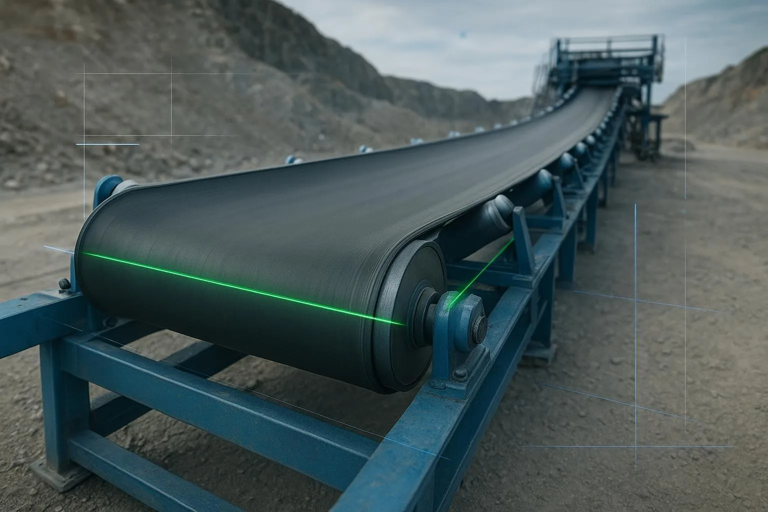
Concisely, a belt conveyor uses a continuous belt loop supported by idlers and driven by a head pulley to transport material between two points. Design choices—belt family, idler set, pulley sizing, drive power, and take-up—determine capacity, efficiency, and uptime. Safety controls, proper loading, and routine maintenance keep the system reliable.
Key takeaways
-
The phrase Basics of Conveyors: Technical Summary covers component definitions, operating principles, selection steps, safety, and upkeep tailored for real plant decisions.
-
Use standards to frame decisions: CEMA (components and tensioning), ISO 5048 (power/tension), DIN 22101 (layout and resistances), and ISO 14890/15236 (belt families and acceptance).
-
Practical success hinges on load-zone design (sealing, support, cleaners), correct tension and wrap at the drive, and disciplined inspection routines.
Basics of Conveyors: Technical Summary—core concepts and components explained
At minimum, a belt conveyor includes:
-
Belt: The load-carrying element with top/bottom covers and a carcass (textile EP/NN or steel cord). Textile belts are common across plant conveyors; steel cord belts serve long, high-tension routes. Belt families and acceptance parameters are defined in ISO 14890 for textile and ISO 15236 for steel cord. For official overviews, see ISO’s catalog pages for the ISO 14890 textile belt specification and the ISO 15236-1 steel-cord series.
-
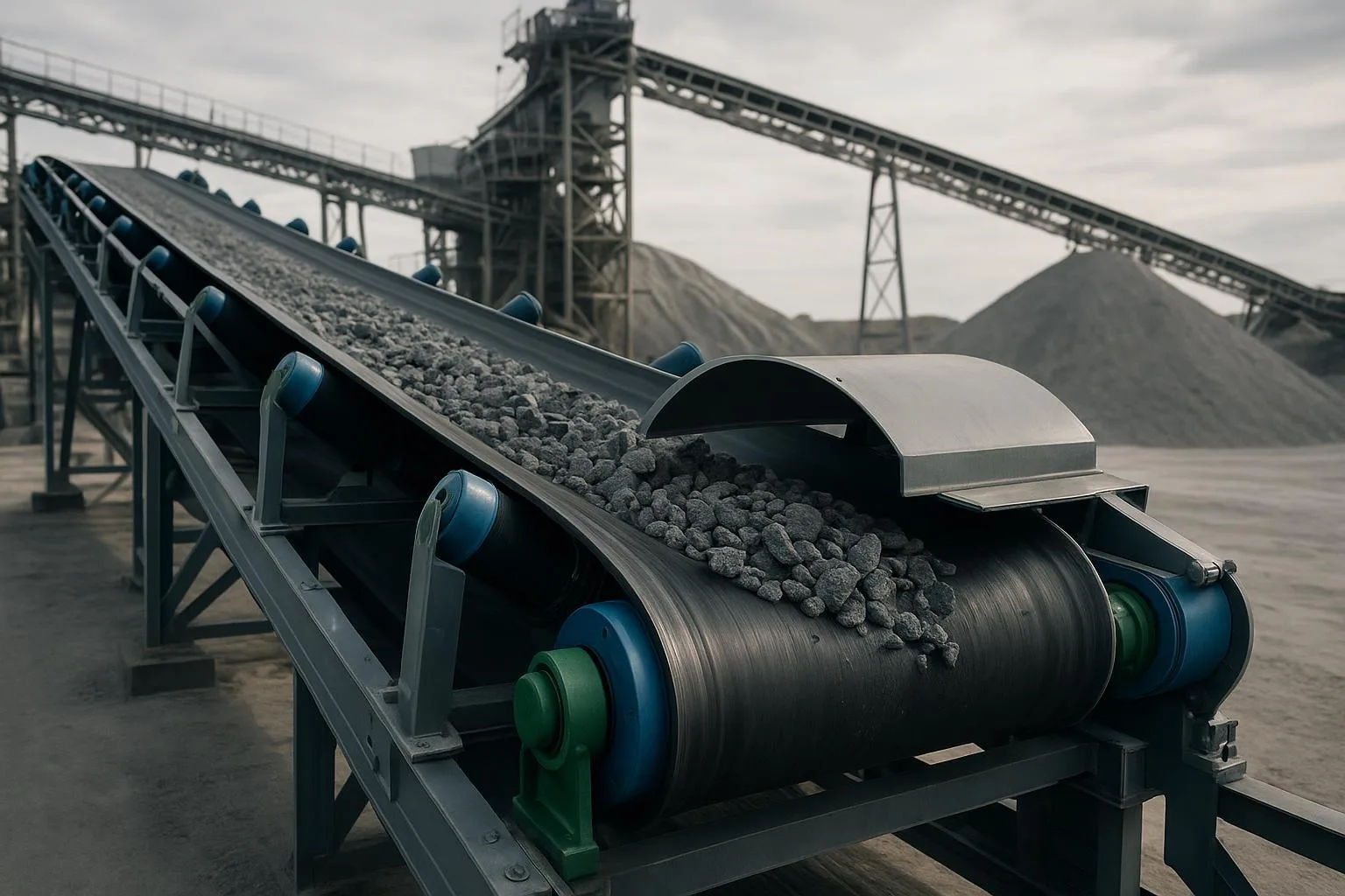
Idlers: Roll sets that support the carry and return runs. Troughing idlers (often 20°, 35°, or 45°) shape the belt into a channel that increases cross-sectional area. Closer spacing under the loading skirt improves support and sealing.
-
Pulleys: Head/drive pulley creates traction; tail pulley turns the belt; snub and bend pulleys increase wrap and guide the path. Lagging (ceramic or rubber) on the drive pulley helps friction, especially in wet or sticky conditions.
-
Drive: Motor and gearbox sized for the required effective tension and belt speed.
-
Take-up: Screw (manual) or gravity devices maintain belt tension. Gravity take-ups are preferred for long or variable-load conveyors.
-
Transfers and sealing: Chutes, liners, and skirtboards place material onto the belt after it has fully troughed; sealing minimizes spillage and dust.
-
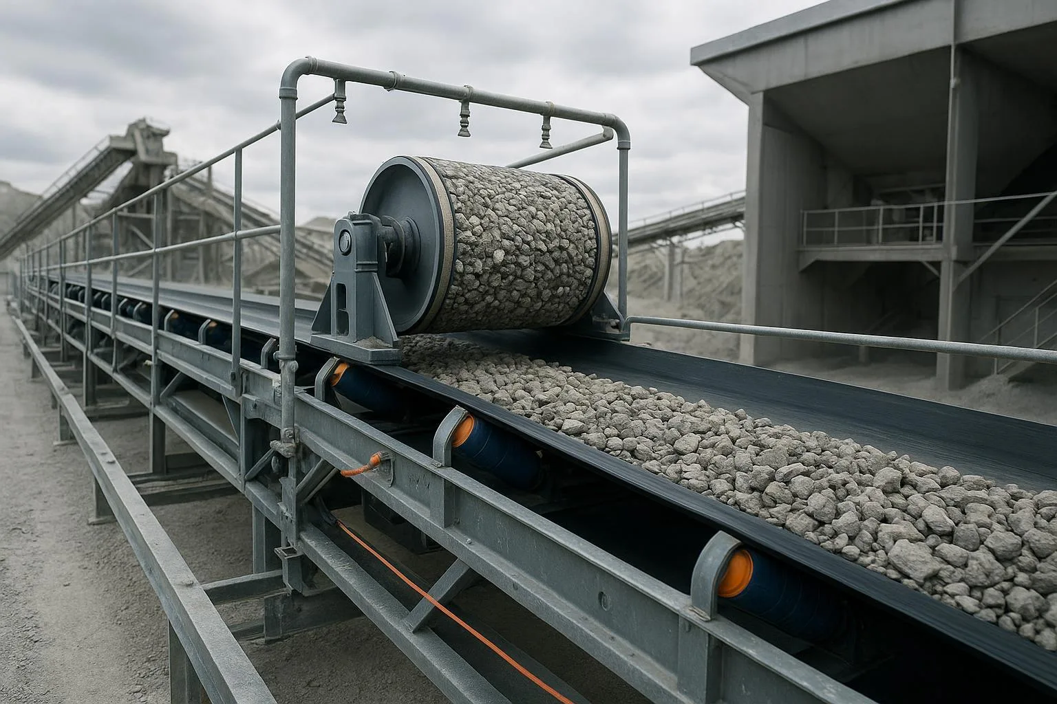
Belt cleaners: Primary and secondary cleaners remove carryback and protect return idlers and pulleys.
-
Safety devices: Emergency pull-cords, local E-stops, misalignment switches, zero-speed switches, and guarding at nip points are common controls.
A few operating principles guide how these components work together: traction and wrap at the drive; effective tension and sag management; careful flat-to-trough transitions; and tracking, which relies on clean, centered loading and square alignment.
Authoritative frameworks you’ll see referenced throughout include CEMA’s Belt Conveyors for Bulk Materials (7th ed.) for components and tension methods (see the CEMA 7th Edition overview); ISO 5048 for power and tensile force calculations (see the ISO 5048 standard overview); and DIN 22101 for layout fundamentals and resistance categories (see DIN 22101 basis for dimensioning summary).
EP/NN vs. steel-cord belts—what’s different and when to choose
For belt family definitions, consult the ISO 14890 textile belt specification and the ISO 15236-1 steel-cord series.
Where belt conveyors fit—practical applications
Mining overland: A single-flight route crossing undulating terrain might run several kilometers with curved alignments. Capacities can exceed 1,500 t/h with speeds beyond 4 m/s depending on material and sealing. For credible upper bounds and real-world examples, see BEUMER’s overview of overland belt conveyor systems with capacities up to 10,000 t/h.
Cement plant feed: Quarried limestone or clinker transfers run at moderate speeds (often 1.5–3.5 m/s) to control wear, dust, and spillage. Shorter conveyors with textile belts are common. Load zones benefit from 20° troughs near the chute for sealing, then 35° downstream for capacity.
Port shiploader transfer: High-throughput, frequent stop/start operation with strict dust control. Expect robust skirtboard sealing, primary/secondary cleaners, and ceramic lagging at the drive to resist moisture and fines.
For a broader survey of use cases, see the internal guide to industrial uses of belt conveyor systems across sectors from BisonConvey.
Basics of Conveyors: Technical Summary—selection and implementation guide
A simple, defensible path beginners can follow looks like this:
-
Define the duty. Material (size distribution, density, moisture, abrasiveness, surcharge angle), throughput target (t/h), geometry (length, lift, routing), and environment (heat, corrosion, explosive atmospheres). Note any regulatory overlays (e.g., underground standards or ATEX).
-
Outline geometry. Fix endpoints, transfer points, and maintenance access. Decide on straight vs. curved routing and space for a gravity take-up if needed.
-
Choose the belt family and initial spec. For most plant conveyors, start with a textile EP/NN per ISO 14890; for long/high-tension routes, consider steel cord per ISO 15236. Define width, cover grades and thicknesses, and carcass rating.
-
Select idlers and trough angle. 20°, 35°, or 45° depending on sealing needs and capacity. Close spacing under the skirtboard; typical spacings increase downstream. Troughing guidance aligns with industry practices summarized by AT Minerals and similar engineering sources.
-
Size pulleys and lagging. Confirm minimum pulley diameters for the chosen belt family. Add ceramic or rubber lagging to the drive as conditions require.
-
Check power and tension. Use ISO 5048 or CEMA methods to compute effective tension and verify slack-side tension against slip and sag criteria. Adjust take-up, wrap, or lagging as needed.
-
Engineer the load zone and cleaners. Load after the belt fully troughs; keep adequate free belt edge; install primary/secondary cleaners and plan for tension checks.
-
Plan safety and maintenance. Integrate pull-cords/E-stops and guarding. Define inspection cadence and housekeeping. Comply with local regulations and consensus standards.
For a concise collection of standards, OEM manuals, and calculators, see BisonConvey’s Conveyor Belt Design Resources — Engineer’s Ultimate Guide.
Worked example 1: quick capacity and speed sanity check
Goal: Move 600 t/h of crushed limestone, ρ ≈ 1.6 t/m³, with moderate lump size and good sealing.
-
Pick an initial belt width: 900 mm (36 in) is common at this duty. Ensure width also satisfies lump-size clearance rules.
-
Cross-sectional area A depends on trough angle and surcharge angle (material repose minus a few degrees). Using standard capacity charts, a 900 mm belt at 35° trough can carry roughly 0.06–0.08 m² of material section.
-
Capacity Q ≈ A × v × ρ. If A ≈ 0.07 m² and ρ ≈ 1.6 t/m³, then v ≈ Q / (A × ρ) ≈ 600 / (0.07 × 1.6) ≈ 5,357 m/h ≈ 1.49 m/s.
-
Check speed range: 1.5 m/s sits in common practice for abrasive stone, balancing wear and dust. If sealing allows and transfer limits are met, 1.8–2.2 m/s could reduce belt width or idler loading.
This is a “back-of-the-envelope” check; use CEMA/ISO charts to refine A and validate surcharge angle assumptions.
Worked example 2: rough power/tension per standard methods
Assume the same conveyor: 900 mm belt, 1.8 m/s speed, 120 m length, 12 m lift. Compute effective tension Te using ISO 5048 or CEMA guidelines (framework only here):
-
Determine primary and secondary resistances and lift resistance to get the total driving force Fu.
-
Effective tension Te ≈ Fu at steady state. Slack-side tension T2 must satisfy both slip and sag criteria. One common check uses a slip criterion based on wrap and friction (a method summarized in many CEMA-based resources). Drive power P ≈ Te × v.
-
If the preliminary calculation yields Te ≈ 6 kN, then P ≈ 6,000 N × 1.8 m/s ≈ 10.8 kW. Add allowances for starting, friction uncertainties, and accessories, and select the next standard motor size.
For a guided calculator and webinar explaining the CEMA-style approach, see Rulmeca’s bulk handling power calculation program and training resources.
Note: Always confirm take-up travel, pulley diameters, and splice ratings against the chosen belt family (ISO 14890 or ISO 15236) and your final Te and T1/T2.
Micro example: component package fit (neutral)
On a plant retrofit handling 400 t/h cement clinker, a supplier package that includes a textile EP belt, CEMA-class troughing and return idlers, and a ceramic-lagged head pulley can simplify commissioning because belt, idler load ratings, and lagging are pre-matched to the basic duty. This is the kind of bundle a firm like BisonConvey supplies for heavy-duty plants, and it can be adapted to your geometry and take-up arrangement. The value is compatibility and fewer interface risks, not a change in the underlying standards.
Installation and commissioning essentials
Before any hands-on work, apply lockout/tagout, verify zero energy, and secure guards and barricades. In the U.S., OSHA 29 CFR 1910.147 (LOTO) and 1910.212/219 (guarding) set the baseline; ANSI/ASME B20.1 provides industry consensus practices for conveyor safety controls. An overview of the employer duties is summarized in this readable OSHA-focused conveyor safety explainer.
Commissioning sequence, summarized in prose to keep the focus on essentials: Verify frames, idlers, and pulleys are square and aligned; spin idlers to confirm free rotation and change any with rough or noisy bearings. Inspect splice length, steps, and squareness and confirm transition distances to protect the carcass. Set take-up travel and counterweight (if gravity) to meet the design sag target, then recheck after the first loaded run. In the load zone, set skirtboard gaps and liner angles, add impact idlers or slider rails, and make sure loading occurs after the belt is fully troughed. Tension cleaners per the manufacturer and check access for ongoing adjustments. Finally, perform functional tests for pull-cords and local E-stops, verify zero-speed switch action and interlocks, and confirm pre-start alarms.
For a step-by-step field checklist and visuals, see BisonConvey’s Conveyor Belt Installation Guide — Ultimate Guide.
Troubleshooting and maintenance—conveyor basics you can apply today
Mistracking (belt drifting to one side) often traces back to alignment and cleanliness. If drift appears the same empty and loaded, look first at idler/pulley squareness and splice squareness. If drift flips under load, focus on centered loading and return-side cleanliness. Replace seized idlers and remove buildup before you try to “steer” with the drive.
Slippage at the drive shows up as material left on the drive pulley, heat or discoloration, and lagging glazed with fines. Raise slack-side tension at the take-up, add wrap with a snub pulley, restore lagging, and improve upstream cleaning.
Spillage and carryback suggest poor transfer design, inadequate skirting, or excessive sag. Rework skirtboard geometry, support the belt under the skirt with closer idler spacing or slider rails, and maintain cleaner tension; add a secondary cleaner if carryback persists.
Seized or frozen idlers announce themselves with noise and localized wear. Replace immediately, then audit alignment and housekeeping to prevent recurrence.
A pragmatic maintenance cadence balances vigilance with realism. On daily or shift rounds, walk the tail, transfers, and head, check pull-cord integrity, and listen for unusual sounds. Weekly, check cleaner tension and blade wear, spot-check idler noise and temperature, verify take-up position, and inspect lagging condition. Monthly or quarterly, inspect the splice and belt covers, audit skirtboard seals, and measure cover thickness at a few reference points. Annually, run an alignment survey, perform pulley NDT if applicable, and complete a full controls function test.
For rules of thumb on skirtboard sizing, free belt edge allowances, and load-zone support that align with common practice, see AT Minerals’ overview of conveyor specification pitfalls and rules of thumb. For tracking specifics, BisonConvey’s guide to how to diagnose and correct belt mistracking provides a field-tested decision path.
Conclusion—actionable takeaways
-
Define duty and geometry first; don’t jump to components before you know the tph, lift, routing, and environment.
-
Choose the belt family (EP/NN vs steel cord) based on length and tension. Use ISO 14890 and ISO 15236 to pin down acceptance criteria.
-
Select idlers and trough angle with sealing in mind; many plants use 20° in the loading zone, 35° downstream.
-
Size pulleys, compute tension/power with ISO 5048 or CEMA methods, and verify take-up travel and wrap.
-
Engineer the load zone: support under skirts, correct free-edge, and cleaner access. Good housekeeping and cleaner tensioning reduce carryback and spillage.
-
Build safety and maintenance into the design. Guarding, pull-cords, and a realistic inspection cadence are not optional.
A soft next step: If you want a sanity check on belt family, idler class, and pulley lagging for a new spec or retrofit, share your duty and geometry. A supplier such as BisonConvey can review options for belts, idlers, and pulleys and suggest component packages aligned with CEMA/ISO/DIN without changing your basis of design.
Selected references and further reading (descriptive anchors):
-
CEMA 7th Edition: scope for components and tension methods — see the official CEMA 7th overview and product page: https://cemastore.com/product/cema-belt-conveyors-for-bulk-materials-7th-ed-eng-book-pdf/
-
ISO 5048 power/tension method — ISO 5048 standard overview: https://www.iso.org/standard/11069.html
-
DIN 22101 layout fundamentals — DIN 22101 basis for dimensioning summary: https://www.intertekinform.com/en-gb/standards/din-22101-2011-12-429650_saig_din_din_970826/
-
ISO 14890 textile belts — ISO 14890 textile belt specification: https://www.iso.org/standard/61047.html
-
ISO 15236 steel-cord belts — ISO 15236-1 steel-cord series: https://standards.iteh.ai/catalog/standards/cen/71809687-f4fb-4969-b157-22d0c392eac8/en-iso-15236-1-2016
-
Power/tension calculator — Rulmeca bulk handling power calculation program: https://rulmecacorp.com/bulk-handling-power-calculation-program/
-
Capacities and overland context — BEUMER overland belt conveyor systems: https://www.beumergroup.com/products-systems/conveyors-technology/overland-belt-conveyors/
-
Rules of thumb for load zones and sealing — AT Minerals conveyor design pitfalls and rules of thumb: https://www.at-minerals.com/en/artikel/at_conveyor_rules_of_thumb_-3752877.html
-
LOTO/guarding baseline — OSHA-focused conveyor safety explainer: https://customconveyor.com/conveyor-safety-standards-osha-requirements/
Internal resources for deeper practice:
-
Design methods, standards, calculators — Conveyor Belt Design Resources — Engineer’s Ultimate Guide: https://bisonconvey.com/blog/conveyor-belt-design-resources-ultimate-guide/
-
Installation and commissioning — Conveyor Belt Installation Guide — Ultimate Guide: https://bisonconvey.com/blog/conveyor-belt-installation-ultimate-guide/
-
Troubleshooting tracking — How to Fix Conveyor Belt Misalignment (Mistracking): https://bisonconvey.com/blog/how-to-fix-conveyor-belt-misalignment-guide/
-
Industry applications and examples — Industrial Uses of Belt Conveyor Systems — Ultimate Guide: https://bisonconvey.com/blog/industrial-uses-belt-conveyor-systems-ultimate-guide/