Recycling Plant Sorting Process — Engineer’s Ultimate Guide
As engineers and procurement teams evaluate upgrades, the Recycling Plant Sorting Process is where throughput, purity, safety, and uptime converge. This guide maps the end‑to‑end material recovery facility (MRF) flow—from receiving to baling—then goes deep on equipment choices, conveyor system design, standards, and maintenance. We reference CEMA for conveyor design, ISO 5048/14890/15236 for power and belt specifications, ASME B20.1 for conveyor safety, OSHA 1910 for guarding/LOTO, and NFPA 654 for combustible dust. The goal: help you specify, retrofit, or procure with confidence.
Key takeaways
-
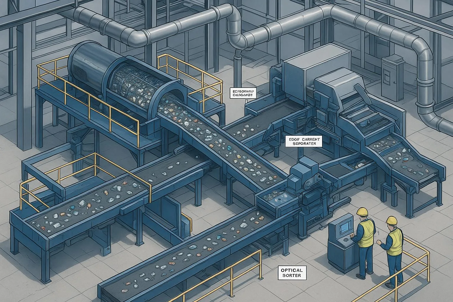
A modern MRF line combines size/shape separation, magnetic/eddy current recovery, and optical/AI identification with manual QC.
-
Conveyor fundamentals—belt width and speed, idler spacing, transfer chutes, and skirting—determine stability at each sorting device.
-
Use standards as anchors: CEMA (design), ISO 5048/14890/15236 (power/belt specs), ASME B20.1 and OSHA 1910 (safety), NFPA 654 (dust).
-
Start with KPIs: throughput (TPH), capture and bale purity, uptime, energy per ton, and safety observations.
-
Commission for reliability: align tracking, time PLC/VFDs to sorters, and keep optical air quality and lens surfaces clean.
Recycling Plant Sorting Process: Core concepts and flow
From receiving to baling
A typical Recycling Plant Sorting Process follows this path: collection delivery → tip floor/receiving → pre‑sort (remove hazards and large contaminants) → screening/shape separation → ferrous and non‑ferrous recovery → optical/AI sorting → manual quality control → baling and outbound. Industry explainers outline this hybrid approach that blends equipment with QC stations across the line, consistent with the process described by the Atlantic Packaging team in their 2024 deep dive on modern MRFs (see their MRF process explainer).
Screening and shape separation
Screens stabilize downstream sorting by classifying material by size and shape.
-
Trommel screen: Rotating perforated drum (≈10–25 rpm, 3–7° incline). Works well on sticky or wet feeds; separation by hole size. Typical municipal perforations range from ~8–12 mm for fine paper up through larger openings for containers. Reference OEMs provide ranges and selection notes. For general context, see KOMPLET and Spaleck overviews of trommel fundamentals.
-
Disc screen: Rows of rotating discs agitate and convey material; unders fall through set openings defined by slot length and interface opening (IFO). Effective for separating flat fibers from 3D containers. See disc screen fundamentals and best practices.
-
Ballistic separator: Oscillating paddles sort 2D (paper/films) vs 3D (bottles/cans) while fines drop through perforations. Deck angles commonly 15–20° with sieve openings 20–60 mm. OEM references (MetalTech, Parini, Bianna, Bollegraaf) corroborate these ranges; see an application‑focused perspective in VDRS guidance on ballistic separator placement.
Two compact tables follow to support selection.
Table 1. Screening technologies at a glance
Metal recovery: magnets and eddy currents
-
Overband magnets pull ferrous from burden depth; selection depends on belt width, gap, and expected ferrous size/shape. Permanent units often measure ≈4–8 kG at the surface; electromagnetic units can exceed 10 kG. Industry notes on magnet selection and working gaps are summarized by magnet OEMs; see their application notes for detailed gauss vs gap curves.
-
Eddy current separators (ECS) repel non‑ferrous metals using a high‑speed magnetic rotor. Rotor type and rpm depend on particle size. Concentric rotors suit >20 mm items; eccentric/high‑frequency rotors suit smaller fractions. See Bunting and Dings application notes for configuration heuristics like splitter tuning and belt speed.
Table 2. ECS rotor selection by size fraction
Authoritative OEM overviews include Bunting’s ECS parameter guidance and Dings’ eccentric vs concentric primer.
Optical/AI sorters and manual QC
NIR/visible optical sorters analyze spectral signatures to identify polymers (PET, HDPE, PP) and paper grades, firing ejector valves to separate target fractions. AI‑assisted vision and robotics increasingly provide real‑time composition data and automated picks; recent industry coverage shows enhanced detection resolution and intelligent MRF development. For a current snapshot, see NRT’s enhanced detection optics and coverage of AI‑enabled MRFs in Recycling Product News.
Reliability hinges on upkeep: keep NIR windows clean, maintain dry/clean compressed air (~80–100 psi; 20–40 CFM per valve bank typical in practice), test valve responsiveness, and align PLC timing to belt speed and pixel‑to‑nozzle mapping. For maintenance perspectives, see this sponsor note on optical sorting challenges and upkeep priorities.
Practical applications and scenarios
Single‑stream MRF upgrade scenario
A mid‑sized single‑stream MRF (15–25 TPH) seeks higher aluminum and PET recovery. A common upgrade path: add a modern NIR sorter on the container line upstream of an ECS. ECS rotor moves to eccentric at ~3,500–4,000 rpm for 5–50 mm; adjust splitter position to balance recovery vs purity. Upstream, ensure a stable mono‑layer via belt speed control and spreader chutes. Post‑install KPIs: recovery rate of target containers, bale purity vs ISRI/ReMA specs, and downtime from sensor fouling.
Handling films and flexible packaging
Films drive wrap on screens and contaminate fiber bales. Mitigations include: non‑wrapping primary screens, early film extraction with optics, dedicated film bunkers, and dust suppression and capture per NFPA principles where combustible fines exist. Ensure skirts and belt cleaners control carryback that would otherwise foul optics.
Conveyor system design notes (engineer’s lens)
Belt widths, speeds, idler spacing, skirting, and transfer chutes
-
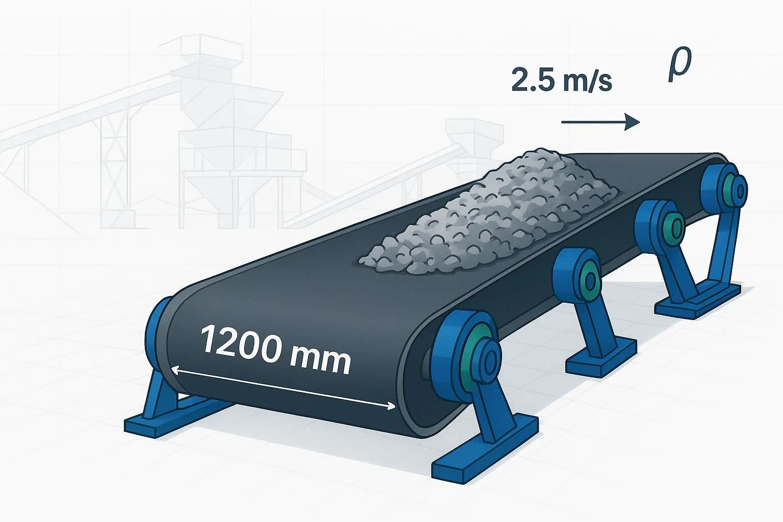
Widths: 18–96 in common; choose width for burden depth at design TPH, largest object size, and transfer geometry.
-
Speeds: Sorting lines often run 0.8–4.0 m/s (48–240 m/min); slower near manual QC to increase pick accuracy.
-
Idler spacing and troughing: Follow CEMA guidance and calculate power/tension per ISO 5048. Maintain adequate free belt edge (≈3.5 in seal, ≈1.0 in mistracking allowance per side) when skirting. Extend skirts past the material’s settling zone and terminate over an idler to avoid belt lift.
-
Transfers and chutes: Stabilize flow with correct lip angles, wear liners, and adjustable splitters. Maintain smooth acceleration into sorters; avoid plumes that confuse sensors.
-
Belt specifications: For surface MRFs, ISO 14890 textiles (EP/NN) are typical; steel cord belts per ISO 15236 apply for long or high‑tension runs. Choose covers for abrasion and heat as needed.
For foundational conveyor selection concepts, see the internal guide Conveyor Belt Design Resources — Engineer’s Ultimate Guide.
Neutral micro‑example (components working together)
On a 1.2 m‑wide container line feeding an ECS, we specified a textile EP belt with 4‑ply covers suitable for abrasion, CEMA‑D idlers at 1.2–1.5 m spacing, and a ceramic‑lagged drive pulley to control slip during start/stop sequences. This combination supported stable mono‑layering at 2.0–2.5 m/s into the ECS without carryback. Components like belts, idlers, and pulleys from BisonConvey can be used in such configurations when matched to calculated tensions (ISO 5048) and CEMA class ratings.
Selection and implementation
Compact selection matrix
Table 3. Choosing core separation technologies
Controls and automation basics
-
PLC/VFD timing: Match sorter firing windows to belt speed and pixel resolution; adjust for latency in valves and communication.
-
Data capture: Log infeed composition, belt coverage, ejection success, and purity. Use closed‑loop targets to tune splitter positions and firing thresholds.
-
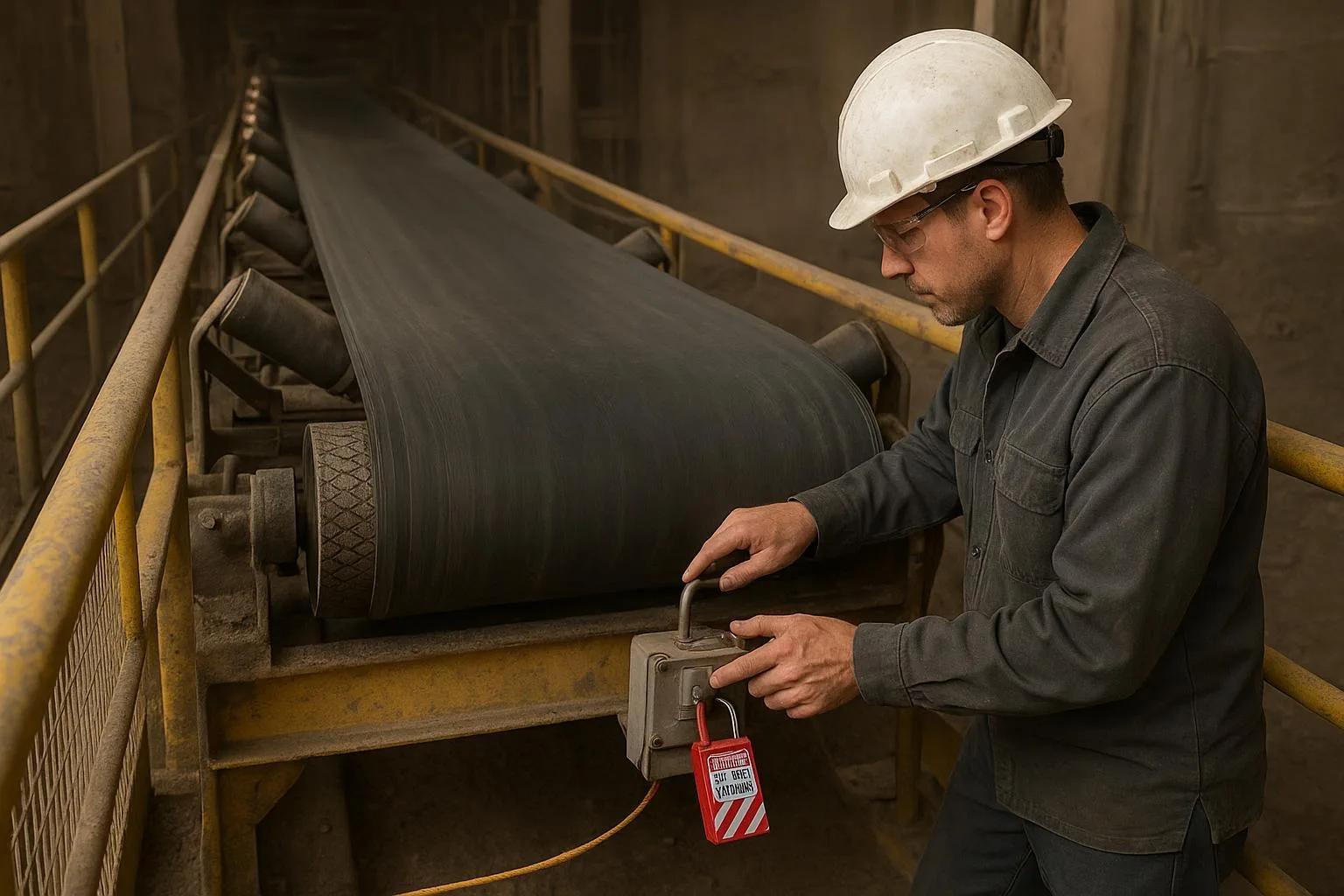
Interlocks and safety circuits: Apply CEMA safety guide logic for E‑Stops (manual reset, no auto‑restart) alongside ASME B20.1 and OSHA 1910.147 expectations.
Safety and compliance overview
-
ASME B20.1 (2024) outlines conveyor safety expectations for design/installation/operation (e.g., guarding nip points, E‑stop behavior). See an overview in ANSI’s summary of ASME B20.1 (2024).
-
OSHA 1910.212/219 govern machine guarding and power transmission; 1910.147 covers lockout/tagout during maintenance. OSHA maintains consolidated access to these requirements; start with OSHA’s machine guarding standards page.
-
NFPA 654 addresses combustible dust hazards in handling particulate solids; MRFs with fines should review dust collection, housekeeping, and recycled air conditions.
-
CEMA safety downloads provide practical guidance for crossovers, E‑Stops, and spill guarding; see CEMA technical downloads.
Always verify local codes and require qualified engineering oversight.
Common problems and troubleshooting
Conveyor tracking, carryback, and spillage
Symptoms: belt edge wander, material fines accumulating under returns, product plumes at transfers.
Checks and fixes:
-
Verify idler alignment and frame squareness; remove buildup.
-
Adjust troughing transitions and load points; ensure skirts are set with correct free edge and follow CEMA guidance.
-
Confirm tension and drive lagging; add or service belt cleaners.
For a deeper playbook on mistracking, see How to Fix Conveyor Belt Misalignment.
Optical sorter fouling and air supply
Symptoms: reduced detection accuracy, weak or inconsistent ejections, nozzle misfires.
Checks and fixes:
-
Clean NIR windows daily; document in CMMS.
-
Maintain dry/clean compressed air; verify pressure and CFM to spec; test valves weekly.
-
Re‑tune firing timing in the PLC after speed changes or belt replacement.
Best practices and maintenance
-
Daily: walk the line; remove entanglers; inspect skirts and cleaners; check E‑Stops and guards as per ASME/OSHA practices.
-
Weekly: verify belt tracking and tension; inspect idlers for noise/heat; clean optical windows; test ejector valves.
-
Monthly: audit transfer chutes and splitter positions; adjust ECS rotor rpm and splitters based on recovery vs purity trend data; check lagging wear and fasteners.
-
Commissioning and major work: use an installation procedure with tension/splice QA and guard verification—see Conveyor Belt Installation — Ultimate Guide.
Document intervals in your CMMS; apply vibration/thermal imaging and motor current analysis for early fault detection.
Conclusion and next steps
The Recycling Plant Sorting Process succeeds when each unit operation is engineered around realistic feed, stable transfers, and well‑maintained conveyors. Start with KPIs, choose separation technologies that fit your streams, anchor conveyor design in CEMA/ISO, and harden reliability with disciplined upkeep and safety compliance.
Actionable next steps:
-
Map your current flow and bottlenecks; set target purity and recovery vs ISRI/ReMA specs.
-
Build a selection matrix for screens, magnets/ECS, and optics based on size fractions and maintenance capacity.
-
Calculate belt tensions per ISO 5048; select belt constructions per ISO 14890/15236 and CEMA classes for idlers/pulleys.
-
Lock in maintenance intervals and PLC/VFD timing reviews; trend KPIs monthly.
If you need belts, idlers, or pulleys matched to calculated loads and environmental conditions, our team at BisonConvey supports custom component configurations for MRF and industrial recycling lines.