3D Conveyor Belt DWG Models for Engineering Design
Accurate 3D conveyor belt DWG models are more than visuals—they’re the backbone of plant layouts, clash checks, installation drawings, and spares planning. If the geometry or metadata is off by a few millimeters, you inherit misalignment, belt mistracking, and costly rework downstream. In this guide, I’ll walk through the standards, workflows, and practical tips I use to produce reliable DWG models that teams can trust.
Key takeaways
-
Build on standards: anchor DWG geometry and documentation to CEMA installation practices and ISO technical drawing conventions; verify OEM dimensions before release.
-
Choose the right format for the job: use native parametric for design intent, export STEP for neutral exchange, and publish 3D DWG for layout/coordination.
-
Control level of detail: keep most assemblies at LOD ~300–350; jump to LOD 400 only near fabrication to avoid bloated files.
-
Govern files: enforce ISO 13567 layer naming with DWT templates; run RECOVER → AUDIT → PURGE before sharing to protect DWG integrity.
-
Parameterize the right things: belt width series, trough angles, idler spacing, and pulley diameters should be named parameters for quick, standards‑aligned changes.
Core concepts engineers must get right
Precise models start with disciplined DWG practices and a clear link to standards.
-
DWG and DWT basics: A DWG is your drawing/model container; a DWT is the template that enforces standards. Autodesk’s guidance explains how templates drive layers, plot styles, and page setups; use CHECKSTANDARDS to flag deviations when files open. See the Autodesk University overview on developing CAD standards in the article titled Developing CAD Standards — Complete Guide (2023+) from Autodesk University: Developing CAD Standards — Complete Guide.
-
ISO layer and drawing conventions: Use ISO 13567 for layer naming and ISO 128/129 for presentation and dimensioning so downstream 2D sheets generated from 3D DWGs read cleanly. ISO’s catalogs outline scope and terminology; align your DWT accordingly. Start from the ISO 128-1 catalog page: ISO 128-1 general rules for drawings and the ISO 129‑1 catalog page: ISO 129-1 dimensioning and tolerances.
-
CEMA installation alignment: CEMA’s Installation Standards (7th Ed., Appendix D) define the tolerances and alignment practices that govern idler squareness, pulley setup, and belt tracking. Model centerlines, idler sets, and pulley faces to reflect those practices. For the official reference, see the CEMA store page for Appendix D: CEMA Installation Standards, Appendix D.
-
Level of detail (LOD):
-
Lite (~200): conceptual layouts, early studies; simplified idlers/pulleys, no seals/fasteners.
-
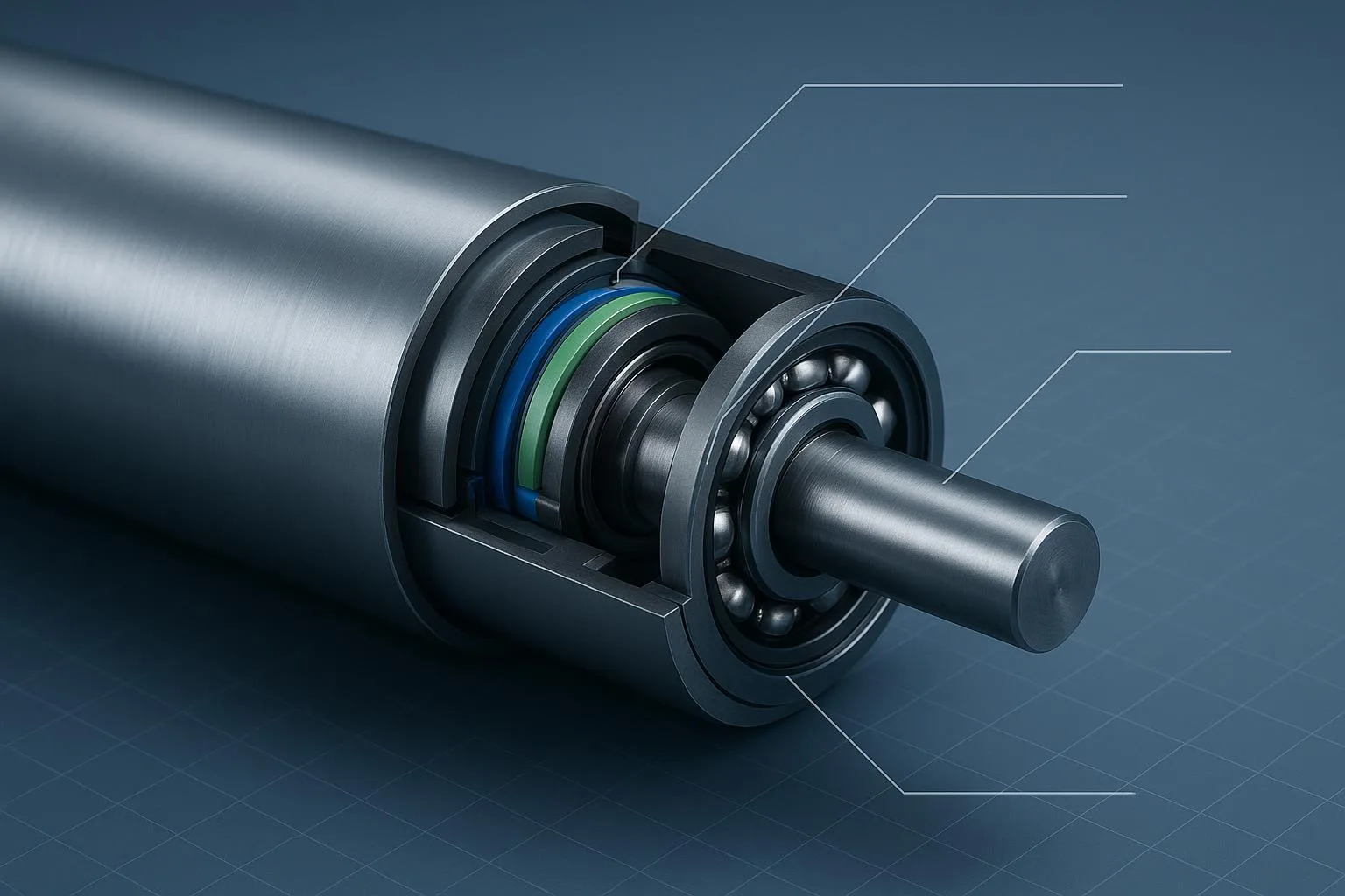
Design (~300–350): clash detection, installation planning; full envelope geometry, accurate shafts/bearings, simplified hardware.
-
Fabrication (~400): near‑release; detail hardware and fits only where fabrication depends on it. Keep these models out of large plant assemblies.
-
-
Parametric anchors to capture:
-
Belt width series (imperial): 18, 24, 30, 36, 42, 48, 54, 60, 72, 84, 96 in (use named parameter belt_w).
-
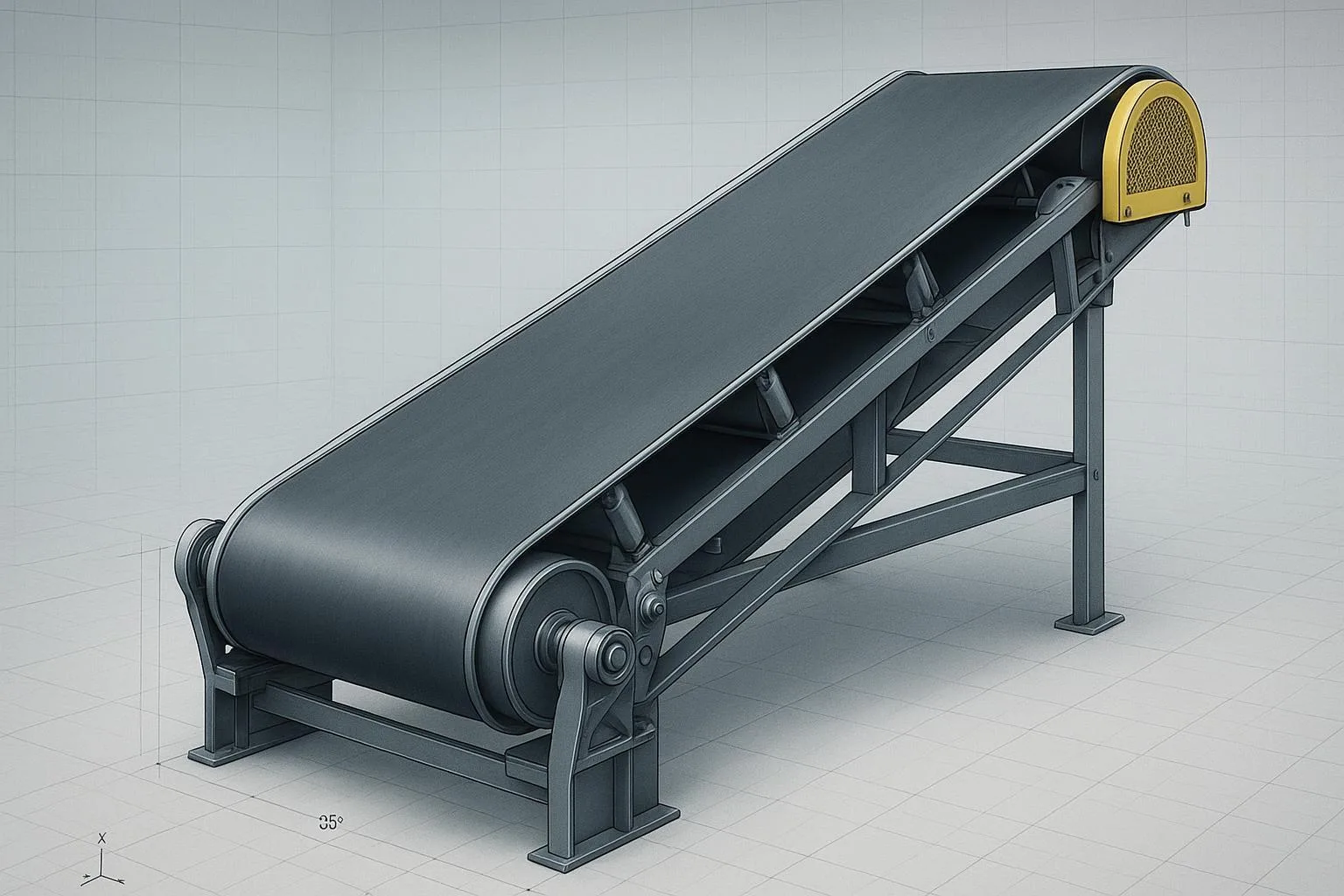
Troughing angles: 20°, 35°, 45° (most plants standardize on 35°).
-
Idler spacing presets: typically ~3.5–4 ft (≈1.0–1.2 m) for many applications; confirm against CEMA tables or your OEM’s engineering manual.
-
Pulley diameters: driven by belt construction and duty; set families for head/tail/bend/snub pulleys.
-
-
Belt construction impacts CAD: EP/NN textile versus steel cord belts change minimum pulley diameter, bend radius, and stiffness, which in turn affects the geometry in your models (transition lengths, take‑up travel). For a primer on belt carcass choices and their implications, see this backgrounder on EP, NN, and steel cord belts: EP vs NN vs Steel Cord Conveyor Belts — mining comparison.
Applications and real‑world use cases
Here are three scenarios that show how 3D DWG models move from design to operations.
Mining overland transfer station
-
Setup: 60 in belt, 35° trough, steel cord ST2000, CEMA E idlers. Head pulley lagged; dual‑drive with torque arms.
-
Workflow: Keep design in a native parametric CAD; export STEP (AP214/242) for FEA; publish a 3D DWG to the civil team for layout/alignment. Use LOD ~350 for transfer chutes and guarding envelopes to support clash detection.
-
Risks managed in CAD: Pulley diameter per steel cord rating; idler spacing vs sag; clear pull‑out space for belt splices; access around take‑up.
Port reclaim conveyor
-
Setup: 48 in belt, 35° trough, EP800/4, CEMA D idlers; humid, corrosive environment.
-
Workflow: Parametric DWG blocks for troughing sets with named parameters belt_w, trough_deg, idler_pitch. Use a DWT aligned with ISO 13567 layers for clear handoff. Export a neutral STEP for equipment vendors; keep DWG for site coordination.
-
Risks managed: Seal selection and bearing types recorded as metadata; idler stand baseplate clearances; guard swing radius.
Cement plant feed conveyor
-
Setup: 36 in belt, 20° trough, EP500/3, CEMA C idlers; tight geometry around bins.
-
Workflow: Use a Lite LOD DWG for early plant layout; only escalate local LOD to ~350 where chutes and drives interface. Convert final 3D views to 2D sheets with ISO 129 dimensioning.
-
Risks managed: Short transition lengths into the 20° trough; chute plug risk; housekeeping access for dust.
Selection and implementation: choosing formats and governing models
Start with this quick decision table, then enforce governance with templates and metadata.
DWG vs STEP vs native parametric for conveyor design
-
Autodesk collaboration and integrity: Current AutoCAD releases add features that reduce geometry errors and improve sharing (e.g., Connected References, geometry cleanup, versioning). See Autodesk’s 2027 overview for context in the article “AutoCAD 2027”: AutoCAD 2027 overview and collaboration features.
-
Template (DWT) essentials: Use a locked, shared DWT that includes ISO 13567 layer naming, title blocks with metadata fields (belt rating, idler class, bearing type), named page setups (PDF mono/color), and dynamic blocks for troughing sets. Autodesk’s standards guide demonstrates how to set and enforce these via CHECKSTANDARDS: Developing CAD Standards — Complete Guide.
-
Naming and metadata schema: Adopt a predictable pattern such as PLT-CONV-ASSY-BW60-TR35-CEMA-E-REV_B and store key properties in file and block attributes (belt_w, trough_deg, idler_pitch, pulley_d_head, bearing_type, CEMA_class). This makes BOM extraction and spares planning straightforward.
-
Sourcing verified geometry: Prefer supplier‑certified catalogs to community uploads. Two widely used portals offering DWG/STEP from manufacturers are TraceParts and 3Dfindit. Start here: TraceParts supplier-certified CAD catalogs and 3Dfindit manufacturer catalogs.
-
OEM portals: When available, use the manufacturer’s own CAD libraries for idlers, pulleys, and components to ensure fidelity. Examples include Dorner’s CAD hub for assemblies and components, Regal Rexnord’s conveying components, and Martin Sprocket’s idler/pulley libraries: Dorner CAD downloads, Regal Rexnord conveying components, and Martin Sprocket CAD library.
Troubleshooting common DWG issues
When a file misbehaves, follow a disciplined integrity routine before you spend hours chasing ghosts.
-
Run RECOVER, then AUDIT (Yes to fix), then PURGE (All; include registered apps). Save to a new filename. Autodesk documents this cleanup sequence in their optimization guidance: see the help article on optimizing AutoCAD drawings titled Optimizing the AutoCAD drawing file — Purge, Audit, Recover: Autodesk help: Purge, Audit, Recover sequence.
-
Resolve scale and unit mismatches. Standardize INSUNITS and check that any incoming STEP/DWG uses the intended units; avoid mixed-inch/mm models.
-
Fix exploded or proxy objects. Replace problem meshes/solids with clean blocks; consider WBLOCK to isolate clean geometry.
-
Clean up XREFs. Bind or detach stale references; set VISRETAIN to keep layer overrides; use relative paths for portability.
-
Migrate versions if needed. If partners run older AutoCAD, batch‑convert with DWG TrueView/TrueConvert to a common baseline (e.g., 2018). Autodesk provides a step-by-step on using DWG TrueView for conversion: DWG TrueView batch convert guide.
If a drawing still fails to open (“Drawing file is not valid”), Autodesk’s recovery notes suggest SAVEAS to DXF as a fallback, then re‑open and re‑save to DWG once stable. See Autodesk’s technical article on this error: Drawing file is not valid — recovery procedures.
Best practices and ongoing model maintenance
-
Version control and reviews: Store source models in a controlled PDM/Vault with lifecycle states; review DWG exports at each milestone to prevent drift from parametric truth.
-
LOD discipline: Keep plant assemblies light; push detail to component drawings. Use Fabrication LOD only when fabrication depends on it.
-
Metadata completeness: Populate belt rating, carcass type, idler class, bearing type, seal type, and revision in title blocks and block attributes. This pays off during spares and BOM generation.
-
Standards checks on open: Enable CHECKSTANDARDS to alert users to non‑compliant layers/dim styles; run it before issue.
-
Supplier verification: Cross‑check downloaded OEM parts against your CEMA class, width, and trough angle parameters before release.
Quick reference: CEMA idler classes and typical use
Use this table as directional guidance; always verify against OEM data and CEMA references for your duty and material.
For context on common classes and uses from a reputable OEM, see Luff Industries’ overview of CEMA ratings in their guide: Understanding the CEMA rating — Luff Industries.
Resources and download sources
Keep links concise and canonical to avoid link sprawl; prefer original publishers.
-
Templates and standards in AutoCAD: Autodesk University’s guide to CAD standards and DWTs: Developing CAD Standards — Complete Guide.
-
DWG cleanup and recovery: Autodesk’s optimization help page: Purge, Audit, Recover sequence.
-
Installation alignment standards: CEMA’s official Appendix D landing: CEMA Installation Standards, Appendix D.
-
ISO drawing conventions: Catalog pages for ISO 128-1 general drawing rules and ISO 129-1 dimensioning.
-
Verified CAD libraries: TraceParts supplier catalogs and 3Dfindit manufacturer catalogs.
Conclusion and next steps
Here’s the deal: if you establish a DWT rooted in ISO 13567, keep design intent in native parametric CAD, export STEP for neutral sharing, and publish clean 3D DWGs that pass the RECOVER → AUDIT → PURGE test, your team will cut coordination errors and speed up commissioning. Start by parameterizing belt width, trough angle, idler spacing, and pulley families; then verify every supplier block against your CEMA class and belt construction.
If you need supplier‑verified dimensions or help specifying belts, idlers, and pulleys for upcoming projects, a practical next step is to coordinate directly with a component manufacturer. BisonConvey supports engineering teams with belt, idler, and pulley specifications aligned to industry standards and can work with your CAD team on custom configurations.