7 steps for conveyor belt alignment
When a belt won’t stay centered, you burn time, spill material, wear edges, and risk safety incidents. Alignment is not just “training the belt”—it starts with structure, then pulleys, idlers, loading, tension, and only then fine training. This tutorial lays out a replicable, safety-first method rooted in field practice and supported by industry guidance.
Key takeaways
-
Alignment is hierarchical: verify structure → pulleys → idlers → tension/splice → loading → training. Skipping ahead wastes time.
-
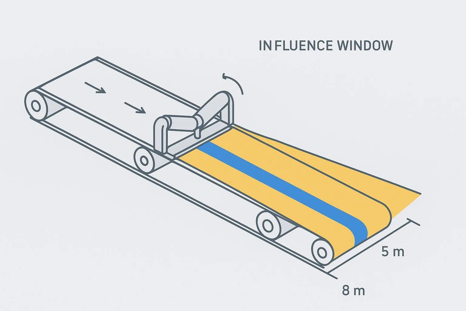
Small, upstream adjustments have the strongest effect within roughly 5–8 m (15–25 ft) downstream.
-
Use measurable checks. As a sanity check on a properly aligned system with centered loading, industry summaries of ISO allow ±40 mm deviation for belts ≤800 mm and ~±5% of width (capped ≈±75 mm) for wider belts.
-
Lockout/tagout (LOTO) and stored-energy controls are mandatory before mechanical work; keep test runs brief and guarded.
Core concepts and standards that matter
Alignment vs. tracking
-
Alignment is the mechanical geometry of the conveyor (structure, pulleys, idlers) relative to the theoretical centerline.
-
Tracking is the belt’s behavior in operation; you “train” the belt only after the geometry and loading are correct.
Why the hierarchy matters
- A perfectly trained belt on a twisted frame will drift again. Confirm the frame and pulleys first, then idlers and loading, then train.
Tolerance and allowance references (publicly available)
-
Structural parallelism during installation: the CEMA Conveyor Installation Standards preview references a ±1/8 in guideline for the back‑to‑back dimension of stringers/beam webs used as truss chords. Treat this as installation guidance rather than an on-the-fly field spec; confirm against your project standards. See the preview via CEMA’s Conveyor Installation Standards (preview).
-
Lateral deviation allowance (sanity check): Industry publications summarizing ISO belt standards report that a correctly aligned, centered-loading conveyor may see lateral deviation of about ±40 mm for belts ≤800 mm wide, or ±5% of belt width up to roughly ±75 mm max. See Canadian Mining Journal’s overview of mis-tracking automation and Coal Age’s feature on actionable mistracking (both 2020s). Use these as high-level checks—not a substitute for OEM/standard limits.
-
Upstream-first and the influence window: Martin Engineering’s Foundations guidance emphasizes adjusting where mistracking begins and notes that an idler change has its strongest effect within about 5–8 m downstream. See Martin Engineering’s “Training the Conveyor Belt” and chapter resources.
7 steps for conveyor belt alignment: the procedure
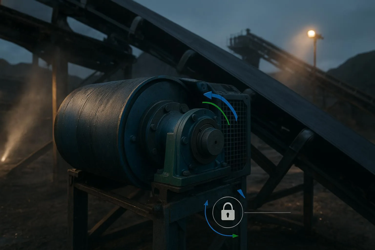
Before any hands-on work: apply OSHA-compliant LOTO and control stored energy. For mining sites, follow MSHA guidance on blocking motion and relieving take-up tension. Keep personnel clear during any test run.
Step 1 — Safety shutdown and clean-up
Purpose: Eliminate hazards and remove the variables that mask root causes.
Tools: LOTO kit and tags, personal locks, torque wrench, scrapers/brushes, PPE; belt clamps and blocks for stored energy control.
Actions:
-
Lock out and tag out all energy sources; verify isolation with a “try-out.” Control stored energy (gravity, springs, hydraulics); block against motion in both directions; relieve take-up tension where procedures require.
-
Clean material buildup from return idlers, snub/drive/tail pulleys, and the load zone. Remove carryback that could push the belt laterally.
-
Inspect and replace seized or flat-spotted rollers before alignment work.
Safety note: Follow OSHA 29 CFR 1910.147 guidance and MSHA’s stored energy alert. Tagout alone is not a substitute when locks are possible.
Verification: Zero-energy confirmed; photos/logs of pre-clean condition; guards ready for controlled test runs.
Step 2 — Verify structure and centerline
Purpose: Ensure the conveyor’s backbone is straight and true.
Tools: String line or laser, steel tape, spirit level, squares/straightedges, feeler gauges.
Actions:
-
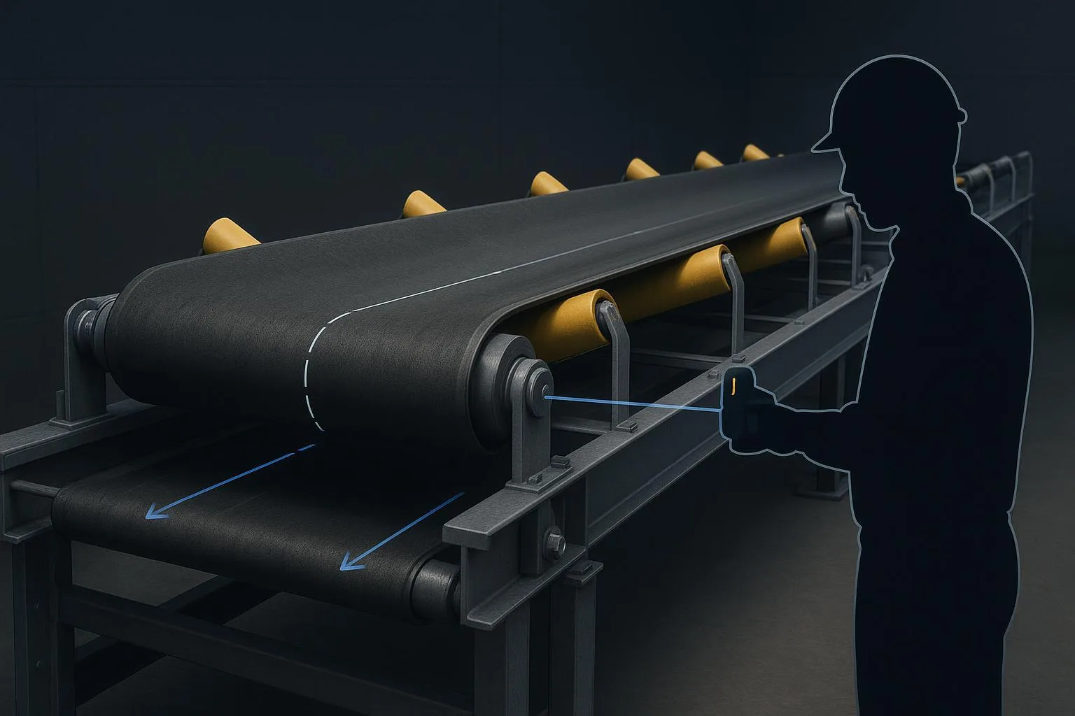
Establish the theoretical centerline along the conveyor length.
-
At three or more stations, measure back‑to‑back stringer dimensions and check for twist. If installation work is ongoing, use the ±1/8 in back‑to‑back guideline from the CEMA installation standards (preview) to set structure.
-
Correct bends or shimming errors in the frame. Do not proceed until the structure is within your project’s tolerances.
Verification: Document measurements; confirm idler/roller support planes are level and perpendicular to the centerline.
Step 3 — Square and inspect drive and tail pulleys
Purpose: Get the belt’s “reference rollers” correct; most tracking issues originate near the drive or where mistracking first appears.
Tools: Straightedge, feeler gauges, laser alignment tool; dial indicator if available.
Actions:
-
Check that the pulley faces are square to the conveyor centerline and that shaft centers are parallel.
-
Inspect lagging for uneven wear or buildup; correct before alignment.
-
If runout checks are feasible, record TIR. Use manufacturer alignment benchmarks as general guidance (e.g., small angular misalignment ~≤0.5°, parallel misalignment on the order of hundredths of an inch per foot span, and low runout per diameter inch), referencing vendor data rather than CEMA for these numbers. See Dodge Industrial’s component guidance: Dodge Industrial—Conveyor Components.
Verification: Belt can run empty without immediate edge contact after reassembly.
Step 4 — Align troughing and return idlers
Purpose: Place belt-carrying and return rolls in a straight, level plane; use idler tilt sparingly as a training aid for single-direction belts.
Tools: Spirit level, alignment rods/sticks, shims, tape, chalk line.
Actions:
-
Ensure idler frames are straight and perpendicular to belt travel; shim frames to remove “smiles” or “frowns.”
-
On single-direction conveyors, a slight forward tilt of troughing idlers (up to about 2° in the direction of travel) can promote centering; avoid this on reversing belts. See PPI’s installation instructions: PPI Belt Conveyor Idler Instructions.
-
Keep return idlers perpendicular to the centerline; replace any that are cocked or different diameters.
-
Make small, incremental changes and then run the belt to observe. Per Martin Engineering, an adjustment has its strongest effect within roughly 5–8 m downstream—focus on the point where mistracking begins.
Verification: Observed improvement within the downstream influence window; record what moved and by how much.
Step 5 — Inspect tension and splices
Purpose: Ensure the belt is tensioned appropriately and that joints don’t steer the belt.
Tools: Take-up inspection access, tension indicators (if fitted), square and straightedge for splice checks.
Actions:
-
Verify take-up travel and tension are within design; over-tension can exaggerate mistracking and damage components.
-
Inspect mechanical or vulcanized splices for squareness and straight tracking through pulleys and idlers. A skewed splice will steer the belt consistently to one side.
-
Confirm fasteners or skives don’t interfere with cleaners or pulleys.
Verification: The belt runs empty with minimal wander after splice and tension corrections.
Reference: Practical splice and tensioning checks are well covered in Flexco’s resources; see Flexco’s “How to Keep Your Conveyor Belt on Track”.
Step 6 — Control loading and skirtboards
Purpose: Center the material load and eliminate side forces from uneven skirting.
Tools: Adjustments at chutes, impact beds/rollers, skirtboard clamps; visual inspection during test load.
Actions:
-
Center the feed onto the belt; adjust deflectors/chutes so material lands near the belt centerline with minimal velocity mismatch.
-
Set skirtboards evenly; avoid excessive, uneven pressure that drags and steers the belt.
-
Use appropriate impact protection to minimize belt bounce at the load zone.
Verification: Under a controlled test load, the belt remains centered through the load zone without rubbing skirting.
Reference: See checklists from Sparks Belting on common causes of misalignment.
Step 7 — Train the belt and verify, empty then loaded
Purpose: Fine-tune tracking after geometry and loading are correct.
Tools: Wrenches for idler frame nudges, observation log, communication devices.
Actions:
-
Start where mistracking first appears; adjust upstream idlers in small increments (millimeters, not centimeters). Shift the idler so the belt “moves toward the end it contacts first.”
-
Run the belt empty 30–60 minutes to stabilize; then run under a representative load for 60–120 minutes.
-
Avoid simultaneous changes at multiple points; assign one person to coordinate adjustments. Document each change.
Verification: As a sanity check—not a target—compare lateral wander to ISO allowances summarized by industry sources: roughly ±40 mm (≤800 mm width) or ±5% of width up to about ±75 mm. See the earlier linked Canadian Mining Journal and Coal Age articles.
Practical applications and real-world scenarios
Mining load zone example (bulk ore)
-
Symptom: The belt drifts left 10–15 mm immediately after the impact zone and worsens to 25–30 mm within 10 m.
-
Actions: Step 6 first—re-center the feed and even out skirt pressure; Step 4—shim two troughing idlers and remove buildup on the left return roll; Step 7—fine-train upstream idlers.
-
Outcome: Drift reduced to within ~10 mm empty and ~15 mm loaded; no edge contact during a 90-minute loaded run.
Port terminal example (reversing belt)
-
Symptom: Wander alternates with direction changes; return trainers placed too close to the pulley.
-
Actions: Step 4—remove direction-sensitive trainers and replace with reversible-capable units; reposition trainers >15 m from pulleys; Step 3—confirm tail pulley squareness.
-
Outcome: Acceptable tracking both directions with minor upstream adjustments.
Neutral brand example (device use case)
- In a plant upgrade, engineers added self-aligning carrying idlers and return trainers after correcting frame and pulley geometry. Using CEMA C class components from BisonConvey helped standardize idler spacing and reduce ad-hoc shimming. Devices were placed sparingly as supportive measures, not as substitutes for root-cause corrections.
Selection and implementation guidelines
When to use self-aligning idlers or automated trainers
-
Use after the system is correctly aligned and loading is centered, to buffer transient disturbances (startup surges, moisture, minor feed shifts).
-
Avoid relying on trainers to mask structural or pulley misalignment.
Placement and selection notes (manufacturer guidance)
- Keep self-aligners a reasonable distance from pulleys (e.g., on the order of ~15 m/≈50 ft) and use at low frequency (for example, one carrying trainer per several dozen idlers). Select reversible-capable trainers for reversing belts. See PPI’s idler instructions and catalogs for model-specific notes.
Idlers and their role in tracking
- If you want a foundational explainer on idlers and their function, see Belt conveyor idlers: definition and why they matter.
Standards-aware selection references
- For a broader context on component selection tied to ISO/CEMA mentions, see our overview in Aggregate and Bulk Transport Options Comparison.
Useful tools during commissioning
- Capacity and burden checks are easier with calculators. Try the Conveyor Belt Capacity Calculator and the Bulk Material Properties Reference to validate assumptions.
Troubleshooting: symptoms, causes, and fixes
Below is a quick-reference matrix to speed diagnosis. Use it alongside your site procedures.
Further reading: For a deeper troubleshooting guide, see How to Fix Conveyor Belt Misalignment (Mistracking).
Best practices and maintenance cadence
-
Assign a single coordinator during training to prevent conflicting adjustments.
-
Document every change and runtime result; photos help future teams.
-
Inspect critical zones monthly (drive, tail, take-up, load zone); clean return rolls routinely to prevent buildup-induced steering.
-
Keep reversible belts free of direction-sensitive trainers; select reversible-capable units.
-
After any structural work, repeat Step 2 measurements before training.
Commissioning checklist (print and adapt)
Pre-run
  - LOTO applied; stored energy controlled; guards in place
  - Structure verified straight/level; centerline logged
  - Drive/tail pulleys squared; lagging clean/intact
  - Idlers aligned; seized rollers replaced; frames shimmed
  - Take-up free and within travel; splice inspected and squared
  - Skirtboards set evenly; impact protection installed

  Empty run (30–60 min)
  - Observe wander; note where mistracking begins
  - Adjust upstream idlers incrementally; log changes

  Loaded run (60–120 min)
  - Verify centered loading and skirt contact
  - Confirm lateral deviation within planned allowance
  - Sign off and store logs for maintenance
Conclusion and next steps
You now have a structured, repeatable method for the 7 steps for conveyor belt alignment: secure the system, verify geometry, correct components, balance tension and loading, and only then fine‑train with measured, incremental changes. Keep adjustments upstream, observe the 5–8 m influence window, and document results for continuous improvement.
If you need engineered idlers, pulleys, or belts specified for demanding duty cycles, our team at BisonConvey can support selections and custom configurations to fit your application.