How to calculate conveyor belt length
Getting conveyor belt length right is the difference between a quick, clean install and days of rework. This guide walks through the geometry for two‑pulley and multi‑pulley layouts, then shows how to translate those numbers into a purchase‑ready cut length using allowances for take‑up travel, splice construction, and belt stretch. We’ll ground the approach in common industry practice and cite authoritative resources where they add clarity.
Key takeaways
-
The geometry gives you installed length; procurement needs geometry plus allowances. Use Lorder = Lgeom + Ltakeup + Lsplice + Lstretch + Linstall.
-
For a two‑pulley open belt, use the exact equation or the common approximation; for complex conveyors, sum straight tangents and wrapped arc lengths (use radians for wrap angles).
-
Take‑up travel, splice allowance, and elongation are not “nice‑to‑haves”—they prevent tracking problems and re‑splicing during run‑in.
-
Reference standards and OEM guidance for tensions/elongation and transitions: ISO 5048, DIN 22101, CEMA, and OEM manuals/blogs.
-
Cross‑check your math with a calculator and, when measuring existing belts, follow strict lockout/tagout procedures.
Core concepts and simple definitions
-
Installed geometric length (Lgeom): The belt path dictated purely by your conveyor’s geometry—straight runs between tangent points plus arc lengths on each pulley. No take‑up, splice, or stretch included.
-
Ordered cut length (Lorder): The length you purchase from a belt supplier. It includes Lgeom and allowances for take‑up travel, splice construction, expected stretch/run‑in, and a small installation reserve.
-
Effective running length: The in‑service length when the conveyor is tensioned and the belt has settled after run‑in; it’s typically longer than the original installed length due to elongation.
-
Wrap angle (arc of contact): The angle over which the belt contacts a pulley. It affects both traction calculations and the geometric arc portion of length.
-
Take‑up: A device (gravity or screw) that adjusts belt tension and compensates for elongation. Your allowance budget must respect available take‑up travel.
-
Transitions and troughing: The belt must transition from flat around a pulley to a troughed profile on idlers. Transition distance that’s too short can overstress edges and cause tracking issues.
How to calculate conveyor belt length: two‑pulley formulas
When the belt runs over two pulleys (open belt, not crossed), there are closed‑form equations for the installed geometric length. Define:
-
DL = larger pulley diameter
-
DS = smaller pulley diameter
-
C = center‑to‑center distance between pulley shafts
-
B = belt length (installed geometry for this simple path)
Exact equation (open belt):
B = (π/2)·(DL + DS) + (DL − DS)·arcsin((DL − DS)/(2C)) + 2·sqrt(C^2 − ((DL − DS)^2)/4)
Approximation (valid when |DL − DS| ≪ 2C):
B ≈ (π/2)·(DL + DS) + 2C + ((DL − DS)^2)/(4C)
Equal‑pulley quick check (DL = DS = D):
B ≈ 2C + π·D
These equations represent pure geometry. For a quick verification of your numbers, you can validate the two‑pulley result with the online Conveyor Belt Length Calculator. The calculator implements the same industry‑standard geometric approximation shown above.
For an accessible walkthrough of the two‑pulley derivation and validity ranges, see the educational explanations published by Omni Calculator in their belt‑length explainer, which present the same forms engineers commonly use in the field. The approximations align with widely taught methods in practical engineering resources: see belt length formulas and example.
Multi‑pulley conveyors: summing straights and arcs
Most bulk‑material conveyors have more than two pulleys: head, tail, snubs, take‑up, and sometimes bend pulleys. The method is straightforward:
Lgeom = Σ(Lstraight,i) + Σ((Di/2)·θi)
-
Lstraight,i are all straight tangent segments between tangent points.
-
Di are pulley diameters.
-
θi are wrap angles in radians on each pulley (convert degrees to radians: θ [rad] = degrees × π/180).
Think of it this way: every straight run is measured end‑to‑end; every wrapped portion contributes an arc length s = r·θ = (Di/2)·θ. Add them up. This geometry‑first approach mirrors how conveyor layout is treated in practitioner texts and design manuals for the belt path. Practical discussion of transitions, idlers, and belt path considerations can be found in Martin Engineering’s Foundations materials, which reflect industry practice for layout and interfaces: see conveyor design and transitions reference.
Tip: Draw or extract the route in CAD and let the software report straight lengths and arc parameters; then check your wrap angles and diameters before summing.
Engineering allowances for ordering: from geometry to cut length
Geometry alone will almost always under‑order a belt. Convert installed geometry into a purchase‑ready cut length with this procurement expression:
Lorder = Lgeom + Ltakeup + Lsplice + Lstretch + Linstall
What each term means and how to estimate it:
-
Ltakeup (take‑up travel reserve): Travel you intentionally include so the take‑up can absorb run‑in/stretch and maintain traction. A practical quantitative guide from Rulmeca states that the minimum movement of a tension unit should not be less than about 2% of the center distance for textile belts and about 0.5% for other cases; treat this as a lower bound for travel budgeting, not as a universal setpoint. Many teams start commissioning near mid‑stroke to preserve adjustment in both directions—note this as common practice and confirm against your OEM documentation. See idler catalog excerpt with movement percentages.
-
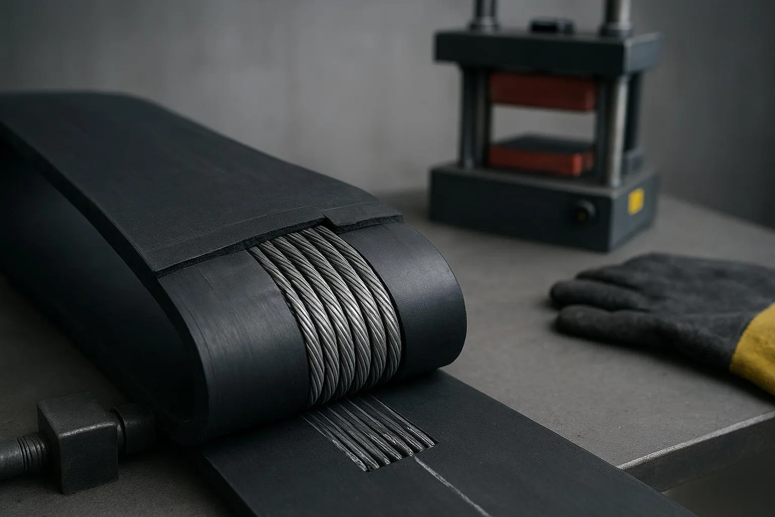
Lsplice (splice construction length): Added length required by the chosen splice method (e.g., hot‑vulcanized stepped splice or mechanical fasteners). Always use the splice drawing from your belt supplier; assuming a generic overlap is risky.
-
Lstretch (elastic + constructional elongation): Elastic stretch can be estimated from belt modulus and tension with ΔL ≈ (T·L)/(E·A), where T is belt tension, E is elastic modulus, and A is belt cross‑sectional area. Constructional (permanent) elongation depends on belt construction and is typically given as a percentage by the manufacturer during run‑in. Frameworks for tensions/elongation are covered in standards; use your belt’s data sheet for the actual numbers. Standards context: ISO 5048 standard page; DIN 22101 reference; CEMA Belt Book, 7th Edition.
-
Linstall (installation reserve): A small additional reserve that eases threading, initial tracking corrections, and future re‑tensioning without re‑splicing. Keep it conservative and consistent with take‑up travel limits.
Below is a quick reference mapping each allowance to drivers and sources.
- Transition distance context near pulleys (rule of thumb): see transition zones overview.
Worked examples
Example A — Two‑pulley conveyor (metric), from geometry to order length
Given:
-
DL = 500 mm (head pulley)
-
DS = 400 mm (tail pulley)
-
C = 7.5 m (center distance)
Check validity for exact formula: C ≥ |DL − DS|/2 → 7.5 m ≥ (0.5 − 0.4)/2 = 0.05 m → valid.
- Installed geometric length (exact):
-
Convert diameters to meters: DL = 0.5 m, DS = 0.4 m.
-
Term A = (π/2)(DL + DS) = (π/2)(0.9) = 1.4137 m
-
Term B = (DL − DS)·arcsin((DL − DS)/(2C)) = 0.1·arcsin(0.1/15) ≈ 0.1·0.0066667 = 0.000667 m
-
Term C = 2·sqrt(C^2 − ((DL − DS)^2)/4) = 2·sqrt(56.25 − 0.0025) ≈ 2·7.499833 = 14.9997 m
-
Bexact ≈ 1.4137 + 0.000667 + 14.9997 = 16.4141 m
- Quick approximation:
-
Bapprox = (π/2)(DL + DS) + 2C + ((DL − DS)^2)/(4C)
-
= 1.4137 + 15.0 + (0.01)/(30) = 16.4137 + 0.000333 ≈ 16.4140 m
-
The approximation is within 0.1 mm—excellent given the large C relative to diameter difference.
- Allowances to get an order length:
-
Ltakeup: Suppose you choose a commissioning travel budget of 1% of C–C for this textile belt application as a conservative starting value (check against your actual take‑up design and OEM guidance). 1% of 7.5 m = 0.075 m.
-
Lsplice: Supplier’s hot‑vulcanized splice drawing calls for 800 mm allowance (example value—use your actual spec). Lsplice = 0.8 m.
-
Lstretch: Assume steady‑state effective tension T ≈ 8 kN, belt modulus E ≈ 1800 MPa (1.8 GPa), belt thickness t = 10 mm, width w = 1000 mm → cross‑section A ≈ t·w = 0.01 m × 1.0 m = 0.01 m². Elastic ΔL ≈ T·L/(E·A) = (8000 N × 16.414 m)/(1.8e9 Pa × 0.01 m²) ≈ 0.0073 m. Add constructional run‑in, say 0.2% of L (supplier typical for EP fabric belts, example only): 0.002 × 16.414 ≈ 0.0328 m. So Lstretch ≈ 0.040 m.
-
Linstall: Keep a small reserve, say 10 mm to 20 mm; take 0.02 m.
- Ordered cut length:
- Lorder = 16.4141 + 0.075 + 0.800 + 0.040 + 0.020 ≈ 17.349 m (round per supplier convention; many vendors accept mm precision).
Cross‑check geometry with a calculator: Validate the two‑pulley geometry with the in‑browser Conveyor Belt Length Calculator. For tensions that inform your stretch estimate, see the Conveyor Belt Tension Calculator, which follows a simplified CEMA framework for early design checks.
Example B — Multi‑pulley troughed conveyor (geometry sum)
Given a route with these straight segments and wraps (metric):
-
Straights: S1 = 12.3 m (carry), S2 = 12.3 m (return shorter due to vertical curve), S3 = 1.1 m (between tail and bend), S4 = 0.9 m (between bend and take‑up)
-
Pulleys: Head D1 = 630 mm with wrap θ1 = 200°; Snub D2 = 315 mm with wrap θ2 = 60°; Tail D3 = 500 mm with wrap θ3 = 180°; Take‑up D4 = 400 mm with wrap θ4 = 90°
- Convert wraps to radians:
- θ1 = 200° × π/180 ≈ 3.4907 rad; θ2 = 60° × π/180 ≈ 1.0472 rad; θ3 = 180° × π/180 = 3.1416 rad; θ4 = 90° × π/180 ≈ 1.5708 rad.
- Arc lengths (s = (D/2)·θ): convert diameters to meters first.
-
Head: (0.630/2)×3.4907 ≈ 1.100 m
-
Snub: (0.315/2)×1.0472 ≈ 0.165 m
-
Tail: (0.500/2)×3.1416 ≈ 0.785 m
-
Take‑up: (0.400/2)×1.5708 ≈ 0.314 m
-
Σ arcs ≈ 2.364 m
-
Sum straights: Σ straights = 12.3 + 12.3 + 1.1 + 0.9 = 26.6 m
-
Installed geometric length: Lgeom = 26.6 + 2.364 ≈ 28.964 m
-
Allowances (illustrative only; use real data for procurement):
-
Ltakeup: Using a conservative 1% of a relevant center distance proxy or an OEM‑specified minimum travel—assume 0.3 m here (align with your take‑up design and Rulmeca guidance for belt type).
-
Lsplice: Supplier drawing requires 1.0 m.
-
Lstretch: Estimate from tension/modulus or use supplier run‑in percentage; assume 0.3% × 28.964 ≈ 0.087 m as an example combined value.
-
Linstall: 0.02 m.
- Ordered length: Lorder ≈ 28.964 + 0.300 + 1.000 + 0.087 + 0.020 = 30.371 m.
Engineering notes:
- Verify transition distances near the head and tail so the belt isn’t forced into a trough too quickly coming off the pulleys; Martin Engineering’s public guidance suggests keeping the flattened transition on the order of 2.5–3× belt width as a rule of thumb (confirm with your belt OEM and layout). If minimum pulley diameters are tight for your belt construction, review them using a quick check like the Pulley Diameter Calculator.
Practical applications and implementation guidelines
-
Communicate geometry and allowances explicitly on purchase documents. List the calculated Lgeom, then each allowance item with its basis (e.g., “Lsplice per supplier drawing X; Ltakeup per take‑up design travel; Lstretch per EP1000 belt data sheet, modulus curve M”). This prevents ambiguity and supports QA during delivery and commissioning.
-
Measuring an existing belt? Use a mark‑and‑measure workflow under full lockout/tagout. Mark a reference point (e.g., the splice), rotate the belt by hand only when fully de‑energized and safely blocked, and record distance after one full loop or between marks. Regulatory guidance emphasizes never relying on start/stop switches for isolation and testing for zero energy after lockout before work proceeds: see lockout/tagout and verification practices.
-
CAD route extraction can accelerate multi‑pulley sums. Model tangent points, extract segment lengths and arc data, and export a calculation sheet for review.
-
When specifying belt type, ensure compatibility with pulley diameters and transition stiffness. For quick orientation on common constructions, see product families like Fabric Belts. Specialty layouts may require sidewall or chevron constructions.
Common problems and how to troubleshoot them
-
Using the equal‑pulley shortcut when pulleys differ significantly. If |DL − DS| isn’t small relative to 2C, the shortcut can mislead; use the exact equation.
-
Forgetting extra pulleys. Snubs, take‑up, and bend pulleys add real arc length. Sketch the entire route and count wraps before you compute.
-
Omitting allowances. A perfect geometric length without Ltakeup, Lsplice, and Lstretch almost guarantees re‑splicing or running out of take‑up travel during commissioning.
-
Transition distances too short. If the belt leaves the pulley and is forced into a trough too quickly, edges overload and tracking wanders. Increase transition length and verify trough angle/idler spacing with OEM guidance.
-
Unknown or unrealistic elongation assumptions. If you don’t have modulus or run‑in data, ask the supplier. As a stopgap, bracket your estimate and ensure take‑up travel can cover the worst case while maintaining traction.
Best practices for design, ordering, and commissioning
-
Document assumptions and data sources (modulus curve, splice drawing, take‑up travel) in the purchase order and project files. Then have a second person verify the numbers.
-
Position the take‑up to preserve travel both ways during commissioning (often near mid‑stroke), within OEM recommendations and minimum movement requirements.
-
Verify minimum pulley diameters and transition distances against the selected belt construction before ordering; adjust idler spacing or trough angles if needed.
-
After installation, re‑measure effective length after run‑in and record remaining take‑up travel for maintenance planning.
Standards and technical references
-
ISO 5048: Belt conveyors with carrying idlers—calculation of tensile forces and power: see the ISO 5048 standard page.
-
DIN 22101: Continuous conveyors—basis for calculation and dimensioning of belt conveyors: see the DIN 22101 reference.
-
CEMA Belt Conveyors for Bulk Materials (Belt Book), a widely used industry text aligning design frameworks for resistances, tensions, and selection: see the CEMA Belt Book, 7th Edition.
-
Transition distance and belt path context: Martin Engineering’s open resources on transition zones: see the transition zones overview.
-
Quantitative guidance for minimum take‑up movement: Rulmeca idler catalog excerpt: see the minimum take‑up movement percentages.
Note: Geometry for belt length is standards‑agnostic, but tension/elongation, traction, and transitions should follow the frameworks and the belt OEM’s data.
A quick tool‑assisted workflow
In practice, engineers often compute the two‑pulley geometry on paper and validate with a web tool, then sum straights and arcs for complex routes in a spreadsheet. For a fast check on geometry or to explore “what‑ifs,” the calculators on the BisonConvey site are handy:
-
Validate geometry: Conveyor Belt Length Calculator
-
Optional reading on tensions (feeds elongation estimates): Conveyor Belt Tension Calculator
-
Quick minimum diameter check for your chosen construction: Pulley Diameter Calculator
Conclusion and next steps
The method for how to calculate conveyor belt length is simple in principle—sum your straight runs and arc lengths for Lgeom, then convert that to an orderable cut length by adding take‑up, splice, stretch, and a small installation reserve. The real engineering work is in choosing sound inputs for those allowances and checking transitions, wrap, and pulley minimums against the selected belt construction. Do that, and you’ll avoid the usual commissioning headaches.
Next steps: If you’d like a second set of eyes on your geometry, allowances, or splice drawings—or you need help selecting the right belt, idlers, or pulleys for your duty—reach out to BisonConvey. You can also sanity‑check your numbers with the in‑browser tools linked above.