meta-title: Rubber Conveyor Belt Visual Resources & Imagery meta-description: Authoritative visuals for belt construction, idlers, pulleys, lagging, splicing, and damage ID. Engineer-led guidance with CEMA and ISO context.
Rubber Conveyor Belt Visual Resources & Imagery
If you spec, buy, maintain, or troubleshoot conveyors, you know that a clear picture beats a paragraph of text. The right visuals—belt cross-sections, idler arrangement images, pulley lagging patterns, splice diagrams, and belt damage identification photos—cut through ambiguity, shorten spec cycles, and prevent costly rework. This guide curates trustworthy “what good looks like” imagery, explains where each visual comes from, and shows how to use it to make faster, safer decisions.
Safety note: Always de-energize and follow lockout tagout before approaching a conveyor. See OSHA’s requirements and training resources for controlling hazardous energy.
Key takeaways
-
Use visuals from authoritative sources and align terminology with ISO and CEMA to avoid spec confusion.
-
Anchor your selection discussions with a belt cross-section diagram, trough angle sketches, and lagging pattern photos.
-
Build a lightweight troubleshooting matrix that links a symptom photo to checks and corrective actions.
-
Treat splicing diagrams as QA tools, not just procedures, so you can spot under-cure, misalignment, or blistering early.
-
Capture your own site-specific images to create a living visual library that shortens maintenance and procurement cycles.
Core concepts you should visualize first
Belt anatomy for textile and steel-cord constructions
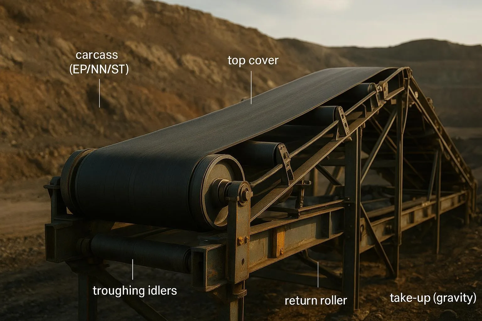
A good conveyor belt cross-section diagram labels the top and bottom cover, skim or adhesion layers, carcass plies, breakers or transverse reinforcements, and, for steel-cord belts, the cord array and edge sealing. Using consistent terminology matters: the ISO 14890 family covers textile-reinforced belts for general use and defines scope and performance requirements. For current scope and edition status, consult the official publisher’s pages such as the ISO overview for textile-reinforced belts and the ISO ICS catalogue confirming the 2026 status.
- According to the ISO catalogue, ISO 14890 sets out requirements for belt construction and cover properties for textile-reinforced belts. See the publisher’s scope notes in the ISO catalogue 53.040.20 listing for the latest status before finalizing specifications.
Plain-language tip: When you present a cross-section to stakeholders, color-code the covers versus carcass and annotate any breakers or edge sealing if your application faces high impact or moisture ingress.
Cover grades at a glance
DIN 22102 and similar standards describe cover grade groupings commonly recognized in industry. Without reproducing protected tables, you can still present a paraphrased, practical comparison that helps teams talk the same language and confirm details with the official text and manufacturer datasheets.
Reference for purchase and verification of requirements is available from the standard’s publisher.
Idlers and troughing visuals engineers actually use
Trough angles and load profile
Most troughed conveyors use 3-roll or 5-roll idlers set at typical trough angles like 20°, 35°, or 45°. Visuals that show belt edge elevation and load distribution help prevent edge tension spikes and spillage in transitions. Manufacturer catalogues and CEMA-compliant idler pages provide clear images of these arrangements.
- Rulmeca’s CEMA E idler page outlines heavy-duty idler families and typical trough angles widely used in industry, including 20°, 35°, and 45° sets. Use these visuals to align discussions of roll diameter, spacing, and duty class with a common reference.
Idler Arrangement Cheat Sheet
Transition distance and tracking cues
Transition distance—the length required for a belt to go from flat at the pulley to fully troughed—deserves a diagram in every spec or commissioning package. Annotations should show the increasing trough angle and the belt edge stress profile. For a clear explanation of this concept and related mistracking prevention visuals, see Martin Engineering’s Foundations knowledge pages on belt transition distance and tracking resources.
For deeper theory and step-by-step alignment images, review the belt tracking diagrams presented in BisonConvey’s internal technical guide.
Pulleys and lagging patterns that matter in the field
Choosing between diamond, chevron or herringbone, and ceramic
Pulley lagging imagery clarifies grip, drainage, and wear expectations. Use authoritative manufacturer diagrams to compare:
-
Diamond or square tile vulcanized rubber for general service with multi-directional drainage channels.
-
Chevron or herringbone for enhanced water shedding in wet or slurry conditions.
-
Ceramic tile for high-tension, high-slip-risk applications where added bite and wear life are needed.
Well-illustrated catalogues from PCI and PPI show these patterns and discuss material and bonding methods. See the PCI conveying components and accessories catalogue for pattern visuals and bonding notes, and PPI’s bulk materials pulley catalogue for selection considerations across pulley families.
Pulley Lagging Selection Guide
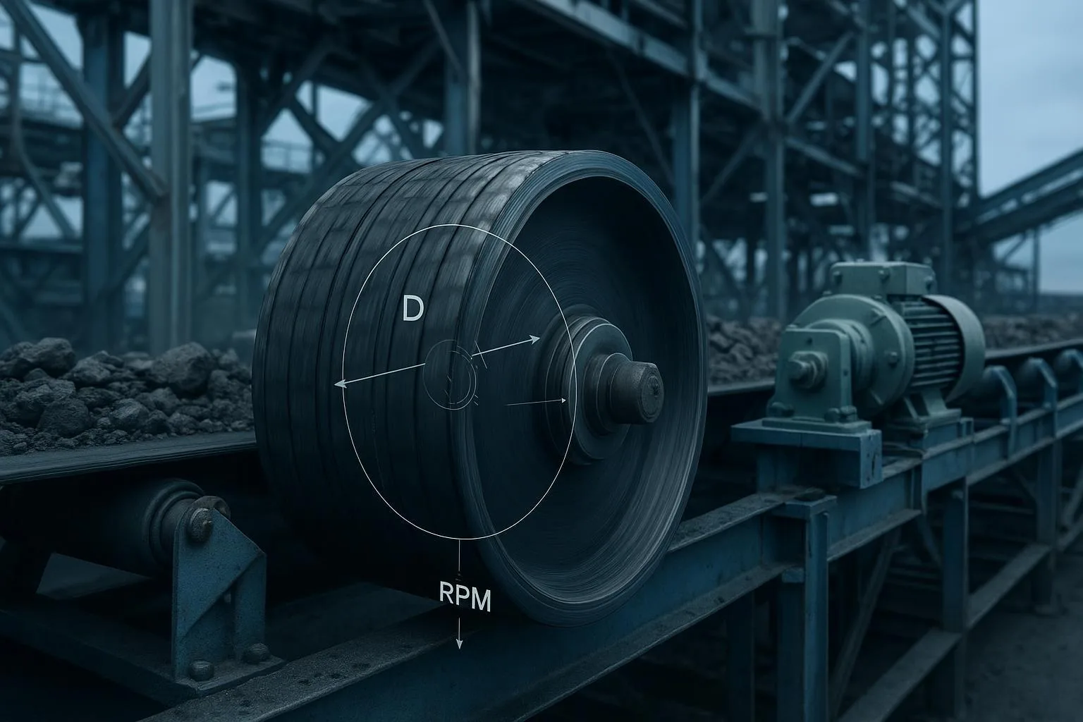
Inspection visuals should also include wear indicators when available. PPI’s documentation illustrates a lagging wear indicator strip that becomes visible as rubber wears, providing a simple visual trigger for maintenance planning.
Splicing diagrams and QA checkpoints
Splice visuals do double duty: they guide the procedure and form a QA checklist. Concept diagrams for finger versus step splices and for mechanical fasteners with skived cover treatments help teams align on the method and quality expectations.
- Flexco’s installation and operation manuals include clear illustrations and photo checklists for hot-vulcanized splice press operation and post-press inspection, including cues for under-cure, bleed-through, and alignment. See, for example, Flexco’s Aero splice press IOM for general QA concepts and pressure, cure time, and uniformity considerations.
Practical QA notes to annotate on your diagrams:
-
Alignment marks continuous through the splice.
-
No blistering or delamination at cover edges.
-
Even skive depth and clean trimming of excess compound.
-
Document cure times, pressure, and temperature alongside photos.
Damage identification photos for safer, faster troubleshooting
A compact library of belt damage identification photos trains the eye and speeds root-cause analysis. Pair each photo with what to check next and what a likely fix looks like. Common visual symptoms include edge fray, cover gouging or cutting, heat glazing or scoring, blistering or ply separation, and splice lift or crooked seam.
Safety reminder before any inspection, cleaning, or tracking adjustment: follow the lockout tagout standard for controlling hazardous energy. OSHA’s general industry standard provides the mandatory framework and training resources.
Selection and implementation using visuals
Turn imagery into unambiguous specs:
-
Cross-sections: Label cover thicknesses, carcass material and ply count, transverse reinforcements, and edge sealing. Cite the applicable scope from ISO 14890 for textile belts and confirm edition status in the ISO ICS catalogue.
-
Idlers: Show the trough angle, roll diameter, and spacing in a side-view sketch. For heavy-duty classes and arrangement visuals, reference a CEMA-compliant source such as Rulmeca’s CEMA E family page to align on duty language.
-
Pulleys and lagging: Add a photo or diagram with the selected lagging pattern and bond type. Cross-check selection notes against PPI’s bulk materials pulley catalogue and PCI materials for lagging types, then capture inspection cues in your maintenance plan.
-
Splicing: Include a simplified splice diagram with QA checkpoints and a photographic record during curing. Flexco’s manuals are a reliable source for widely accepted QA concepts.
Troubleshooting by symptom using a visual matrix
Use a matrix to connect what you see to what you do. Keep it to a single page you can print and carry.
Keep photos high resolution and annotate arrows and labels directly on the image so the action path is obvious at a glance.
Best practices to build a useful visual library
-
Standardize file names so search finds the right view quickly, for example “BeltA_1200mm_35degTrough_IdlerAlignment_2026-05.”
-
Capture before and after photos for every correction and add a one-line metric like “reduced carryback by ~30%.”
-
Host canonical versions on your intranet with read-only access and include a field pack with compressed images for offline use.
-
Add a short legend to every diagram explaining colors, arrows, and units so non-specialists can follow along.
Example and next steps
In one minerals plant, the team used annotated idler alignment images and a side-by-side comparison of pulley lagging patterns to resolve a 6 mm edge wander and recurring slip during rain. The visuals made the decision path clear: correct the transition spacing, re-align the trough set, and switch from diamond to chevron lagging on the drive. Results were tracked over two weeks using the same photo angles.
When you need engineered belt, idler, and pulley solutions supported by clear, standards-aware visuals, a supplier like BisonConvey can provide component options alongside practical diagrams that make implementation and maintenance easier.
For deeper theory and stepwise images on alignment and tracking, see the belt tracking diagrams in our internal guide at BisonConvey’s Conveyor Belt Tracking Theory ultimate resource.
References and further learning
-
Rulmeca CEMA-rated idlers with visuals for troughing angles and duty classes. See Rulmeca’s CEMA E idler family page for heavy-duty arrangements.
-
PCI pulley and lagging patterns with material and bonding notes. See the PCI conveying components and accessories catalogue for open-access diagrams.
-
PPI bulk materials pulley catalogue for selection considerations and lagging inspection features including wear indicators.
-
Martin Engineering’s Foundations knowledge pages on transition distance and mistracking prevention for clear, field-ready diagrams.
-
ISO textile belts scope and edition status. See the ISO overview for textile-reinforced belts and the ISO ICS catalogue for current status.
-
Flexco splice press and cleaner manuals for widely used QA checkpoints and inspection checklists.
-
OSHA controlling hazardous energy resources for mandatory LOTO procedures.
Where exact numeric requirements apply, confirm with the official standard text and your supplier’s datasheet.
Meta notes for SEO
-
Primary keyword used in H1 and section headings: Rubber Conveyor Belt Visual Resources & Imagery.
-
Related phrases included naturally: conveyor belt cross-section diagram, idler arrangement images, pulley lagging patterns, belt damage identification photos, conveyor splice diagrams, CEMA idler visuals, ISO 14890 belt construction.
External source links cited inline in the article above:
-
Rulmeca CEMA E idlers page with trough angle visuals: https://www.rulmeca.com/en/cema-e/112/p
-
PCI components and accessories catalogue with lagging diagrams: https://www.pcimfg.com/wp-content/uploads/2023/04/PCI_Conveying_Components_Accessories_2018R18.pdf
-
PPI bulk materials pulley catalogue and lagging wear indicator overview: https://www.ppi-global.com/userdocs/literature/ppi/documents/pul_001-09_pulleycatalog.pdf and https://www.ppi-global.com/userdocs/literature/ppi/documents/ppi_073-03_strip_relag.pdf
-
Martin Engineering Foundations articles on transition distance and tracking: https://foundations.martin-eng.com/knowledge/conveyor-belt-transition-distance and https://foundations.martin-eng.com/prevent-belt-mistracking-resource-on-demand
-
ISO 14890 overview and ISO ICS catalogue status: https://www.iso.org/standard/61047.html and https://www.iso.org/ics/53.040.20.html
-
Flexco Aero splice press IOM and cleaner IOM for QA and inspection cues: http://documentlibrary.flexco.com/X4298_enSG_4069_AeroGeneration3IOM_102220.pdf and https://documentlibrary.flexco.com/X6056_enUS_6056_FGSecondaryCleanerIOM_112222.pdf
-
OSHA LOTO standard overview: https://www.osha.gov/control-hazardous-energy
Internal link for extended learning:
- Belt tracking diagrams and alignment theory guide: https://bisonconvey.com/conveyor-belt-tracking-theory-ultimate-guide/