
Roller Bed Conveyor Design Principles
Engineer-level guide to roller bed conveyor design: spacing, belt selection, power/tension, noise, and maintenance with CEMA/ISO context.
Roller Bed Conveyor Design Principles
A roller bed belt conveyor—often called belt-over-roller—supports the carrying strand of the belt on closely spaced rollers rather than a continuous slider pan. By replacing sliding friction with rolling resistance, roller beds reduce heat generation, can handle higher loads with lower power, and provide smoother transport for rigid packages and many bulk-like unit loads. They are not the same as roller conveyors (where the product rides directly on rollers without a belt), and they differ from slider beds (where the belt slides on a deck).
Designing these systems well means getting a few fundamentals right: roller spacing and support, belt selection, power and tension, alignment and stiffness, and maintainability. The guidance below aligns with widely adopted methods in the CEMA ecosystem for belt conveyors and draws on unit-handling practices and reputable OEM technical notes.
Key takeaways
Use roller beds when you need lower friction than a slider bed, higher load capacity, or gentler handling for rigid items and cartons.
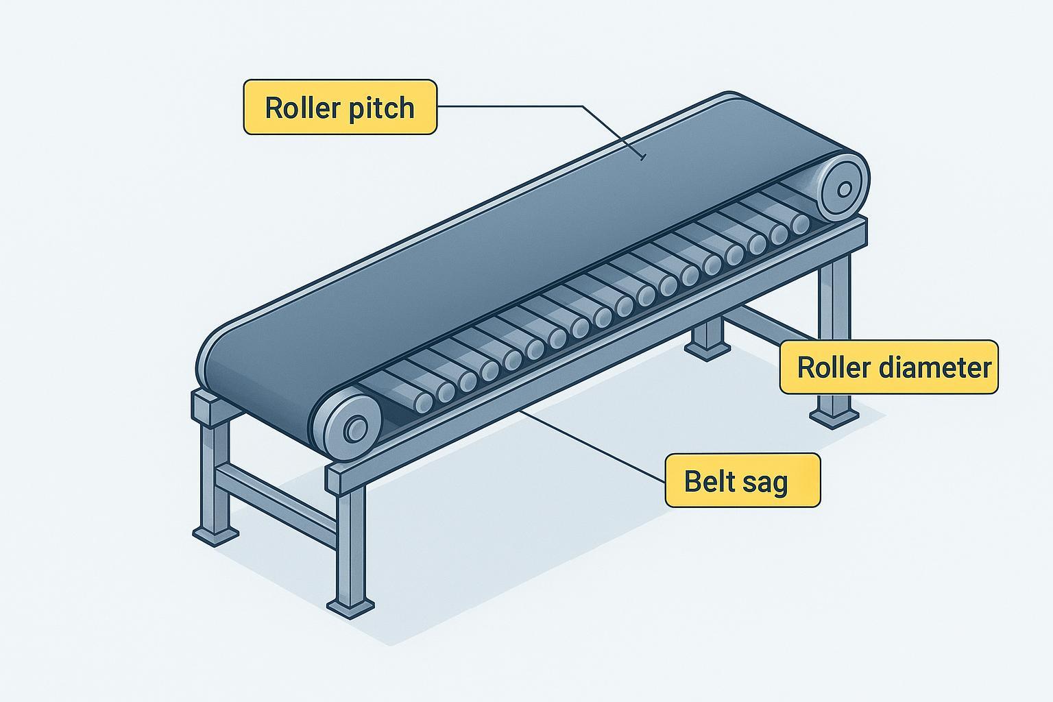
Start roller pitch from the three-roller-under-the-load rule, then verify per-roller load against catalog ratings and refine for stability.
Control belt sag—target low deflection in load and transfer zones—to prevent mistracking, dust, and extra power draw.
Size drives using an effective-tension method; document assumptions for rolling resistance and accessory drag per CEMA-style practice.
Select belt carcass and cover compound for the duty and environment; specify roller diameter, bearings, seals, and expected L10 life.
Engineer for safety and service: guard nip points, provide access, standardize spares, and set inspection intervals.
Roller Bed Conveyor Design Principles in practice
A roller bed conveyor supports the belt with a line of rollers along the carrying strand. The result is lower rolling resistance versus a slider deck, which reduces required power and belt wear in many applications. ANSI/CEMA 402 covers design practice for unit-handling belt conveyors and includes belt-over-roller constructions for widths, speeds, load spacing, and take-up allowances. See the association’s 2019 review material in ANSI/CEMA 402 review notes. For bulk-material design concepts such as power and sag criteria, practitioners often reference the Belt Book framework; CEMA’s official change pages are available via CEMA Belt Book change pages and a fifth-edition excerpt in CEMA Chapter 6 sample.
Comparison with slider beds at a glance:
Attribute | Roller bed belt conveyor | Slider bed belt conveyor |
|---|---|---|
Friction and power | Lower rolling resistance; often lower power for similar duty | Higher sliding friction; more heat and wear |
Load support | Better for rigid, heavier or point-loaded items; can space rollers for stability | Better for very small or flexible items prone to catching between rollers |
Noise | Depends on roller roundness and bearings; can be quiet with quality rollers | Often steady but can squeal at high friction zones |
Typical use | Cartons, totes, baggage, robust packages, many industrial units | Small parts, scan tunnels, locations needing continuous deck |
For selection intuition from unit-handling OEMs, compare guidance from Hytrol’s belt vs live roller overview and IKI’s slider vs belt-over-roller comparison.
Roller spacing and belt support
Three-roller rule and pitch formula
Begin with the stability heuristic used by leading roller OEMs: keep at least three rollers under the load at all times. If the product length is Lp, a simple starting limit for roller pitch P is Lp divided by 2. For tall or unstable loads, target a smaller pitch (for example Lp divided by 2.5) to improve stability. After setting a trial pitch, calculate the per-roller load as the item weight divided by the number of rollers actually supporting it and compare to the roller’s allowable load in the catalog. Larger roller diameters generally increase load capacity and reduce deflection.
Interroll’s planning basics emphasize this three-roller rule of thumb and show how diameter, temperature rating, and bearing type affect capacity and service conditions; see Interroll planning basics for conveyor rollers.
Worked example
Product: 30 in long, 50 lb carton; belt-over-roller on a level run.
Start with P = Lp ÷ 2 = 30 ÷ 2 = 15 in. At that pitch, at least three rollers are under the load.
Supporting rollers under the carton at any instant ≈ 3 to 4; take 3 for a conservative check. Per-roller load ≈ 50 ÷ 3 ≈ 16.7 lb.
Check the chosen roller series at 15 in pitch and required speed; if the series rating per roller comfortably exceeds 16.7 lb with safety margin, the pitch is acceptable. If not, either reduce pitch (e.g., 12 in) or step up roller diameter or wall thickness.
This quick sizing must be followed by a structural check of the bed stringers to control deflection. Excessive frame flex causes tracking issues and roller misalignment.
Belt sag limits in load and transfer zones
Even with roller support, belt deflection between rollers matters. In bulk-handling practice, designers often target about 3 percent maximum sag between idlers for standard runs in tension calculations, with closer support in skirted or loading zones to limit spillage and dust. The same lesson applies to roller beds: tighten spacing where the belt is loaded or transitions, and keep transfer gaps small relative to the product length to prevent edge drop and catching. Martin Engineering’s Foundations resources connect excessive sag to higher power, mistracking, and spillage; see Martin Engineering on idler spacing and belt stability.
Power and tension for roller bed conveyors
The effective tension method in brief
Use an effective tension approach consistent with the CEMA tradition. Compute total resistance as the sum of rolling resistance in the bed, flexure of the belt and load, elevation changes, acceleration, and accessory drag (such as cleaners). Then convert effective tension to power using belt speed.
At a high level in imperial units:
Te = total effective tension in pounds
V = belt speed in feet per minute
HP = Te × V ÷ 33,000
Rolling resistance factors depend on roller quality, belt construction, and loading and are chosen per CEMA-style tables or validated OEM data. Accessory drag (for example, belt cleaners) should be added explicitly using manufacturer data. Rulmeca’s notes illustrate this “sum of resistances” method and provide example values; see Rulmeca on bulk-handling power calculation and Rulmeca’s cleaner-drag example.
Sample horsepower calculation and assumptions
Assume a 200 ft roller bed conveyor moving cartons at 300 fpm. Approximate combined moving weight Wm (belt plus average carried load) as 70 lb/ft. Choose representative resistance coefficients consistent with a roller-supported unit-handling belt, informed by CEMA-style practice. Add a small allowance for accessories.
Baseline rolling resistance component: say 0.02 × Wm × length ≈ 0.02 × 70 × 200 = 280 lb
Flexure and miscellaneous allowances: say 0.01 × Wm × length ≈ 140 lb
Accessory drag for cleaners and skirts: assume 50 lb
Elevation change: zero for a level run
Effective tension Te ≈ 280 + 140 + 50 = 470 lb
Power HP ≈ Te × V ÷ 33,000 = 470 × 300 ÷ 33,000 ≈ 4.27 HP
Select a motor with appropriate service factor and check slack-side tension versus slip criteria, then verify belt allowable tension and minimum pulley diameters per the belt maker’s data. Document the assumed coefficients and adjust after commissioning measurements.
For additional methodology context, see CEMA Chapter 6 sample pages.
Belt and roller selection
Belt carcass and cover selection by environment
Match the belt carcass to tensile demand and the cover compound to the dominant hazard:
Abrasive aggregates and ores need abrasion or cut–gouge resistant covers and a stable fabric carcass with low creep when wet. Representative overviews appear in Conti’s heavy-duty belt catalog.
Hot clinker or asphalt requires a heat-resistant cover rated for the temperature profile and compatible splicing; check pulley diameters for heat service, as discussed in major makers’ catalogs.
Oily grains and wood-based products often need oil-resistant compounds tested to relevant ISO friction and material methods; see ISO catalogue entries for belt specifications in ISO 14890 overview and friction testing context in ISO 21182 topic page.
Regulated sectors may require flame-resistant and anti-static properties per local codes.
When you need a fabric belt baseline or to compare EP and NN options, see BisonConvey’s overview of industrial fabric belting: BisonConvey fabric belts for industrial service.
Roller diameter, bearings, seals, and L10 life
Diameter and tube: Larger diameters carry higher loads and run with lower bearing RPM for the same belt speed, which extends life.
Bearings: Conveyor-optimized deep-groove ball bearings are common; specify dynamic capacity and expected L10 life at your load and speed. ISO 281 provides the classic relation for life versus load and speed; a concise explainer appears in NSK’s bearing life overview.
Seals and lubrication: Choose sealing systems for dust, moisture, or washdown. Decide on sealed-for-life versus relube strategies based on environment and maintenance access.
Temperature: Verify the roller and lubricant operating range against the duty; roller OEMs publish allowable ranges and de-rating notes in their planning documents.
Interroll planning documents remain useful for seeing how diameter, load, and environmental factors interact in roller ratings; see the planning basics link above.
Applications and real-world scenarios
Mining and aggregates: Robust rollers with protective seals and abrasion-resistant belt covers withstand dust and impact. Tighten support in loading zones and keep skirts tuned to avoid carryback. Martin’s Foundations series links sag control to spillage and dust; see belt stability guidance.
Cement plants and terminals: Heat-resistant belts near clinker lines; guard all rotating parts and shield hot surfaces. Verify splice and pulley diameters for elevated temperatures.
Ports and logistics hubs: Long runs benefit from low rolling resistance; noise control may drive selection of high-quality balanced rollers and damping on sheet-metal guards. OSHA’s noise and vibration chapter offers practical controls; see OSHA OTM noise control principles.
Manufacturing and assembly: Mixed carton sizes push toward conservative roller pitch and precision alignment for scanning or weighing stations.
Where inclines demand added traction, patterned belts can help; for steep containment needs on other conveyor classes, sidewall systems are an option.
Troubleshooting common problems
Use symptoms to guide quick checks and fixes. Keep spares on hand for rollers, bearings, and a belt repair kit.
Symptom | Likely cause | Recommended fix |
|---|---|---|
Belt mistracks to one side | Frame not square, rollers or pulleys misaligned, buildup on one side, off-center loading | Square and level the frame, re-align rollers and pulleys, clean buildup, correct loading; consider tracking aids after basics |
Excessive noise or vibration | Out-of-round rollers, worn bearings, loose guards, sheet-metal resonance | Replace defective rollers, swap bearings, tighten and damp guards, verify balance |
Rollers seize or drag | Contamination in bearings, seal failure, impact damage | Replace affected rollers, improve sealing, add deflectors or guards in impact zones |
High power draw | Excessive sag or poor roller condition, accessory drag too high | Tighten support in load zones, replace worn rollers, retension or optimize cleaners and skirts |
Edge wear or splice damage | Mistracking, transition geometry issues, undersized pulleys for belt | Correct tracking, improve transitions, verify pulley diameters and splice type |
Martin Engineering’s Foundations materials provide structured approaches for tracking, cleaner setup, and minimizing spillage and dust. Adopt those fundamentals before adding specialty devices.
Best practices and maintenance
Inspection cadence: Walk the conveyor weekly at minimum in heavy industry; listen for bearing noise, feel for heat at housings, and spot belt damage and buildup.
Bearing life and spares: Estimate L10 life at the selected load and speed; stock at least 10–15 percent of installed rollers and one full set of critical bearings.
Cleanliness and sealing: Keep the belt and rollers clean; set skirt pressure just high enough for sealing; adjust cleaner tension to spec to avoid chatter.
Alignment and stiffness: Check squareness of pulleys and roller sets after any impact or structural work; stiffen flexible sheet-metal guards that ring or buzz.
Safety and guarding: Guard nip points at pulleys and accessible return rollers; provide emergency stops and follow lockout procedures. See OSHA’s general machine guarding rule and conveyor provisions.
Noise reduction tips from OSHA’s technical guidance include reducing drop heights, using isolation mounts, and tightening all hardware to eliminate rattle. Cleaner setup per manufacturer guidance reduces chatter and splice noise.
Conclusion and next steps
Roller bed conveyors reward disciplined engineering: set conservative roller pitch based on product geometry, control sag in load and transfer zones, size drives with an auditable effective-tension method, and specify belts, rollers, bearings, and seals to match the true environment. Build in safety and service access from day one, and the system will run cooler, straighter, and longer. Want a quick litmus test for your current design—does your assumed resistance factor align with what you measured on site?
Actionable next steps:
Define your product envelope, duty cycle, and environment.
Apply the three-roller rule to set initial pitch, then verify loads versus roller ratings and stiffness.
Document power and tension assumptions and validate after commissioning.
Specify belt carcass and cover compounds against the dominant hazard; state bearing L10 targets at operating conditions.
If you’d like engineering support or a custom belt, idler, or pulley specification, contact the team through BisonConvey Contact for an application review and options aligned to your duty.
References and further reading
CEMA Belt Book errata and excerpts outlining power and sag methodology: CEMA Belt Book change pages; CEMA Chapter 6 sample pages.
Unit-handling conveyors standard: ANSI/CEMA 402 review notes.
Roller selection basics: Interroll planning basics.
Power and accessory drag: Rulmeca power calculation overview; Rulmeca belt cleaner drag.
Sag, spillage, and tracking fundamentals: Martin Engineering on idler spacing and stability.
OSHA safety standards: OSHA 1910.212 machine guarding; OSHA OTM noise control.