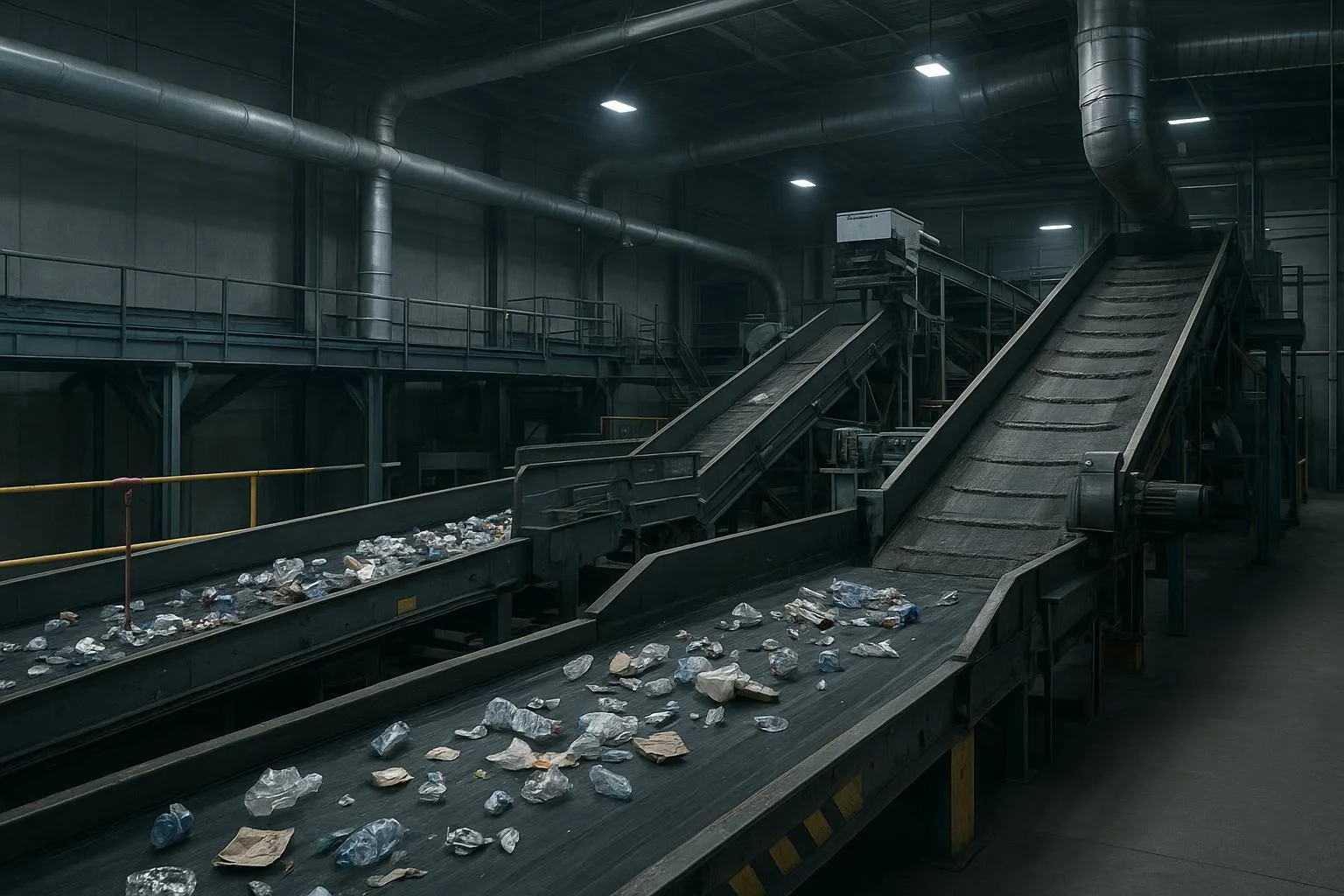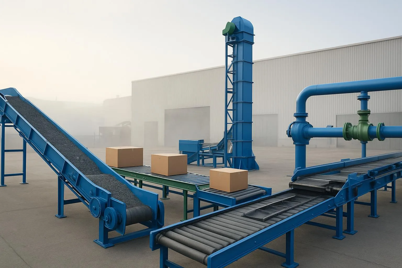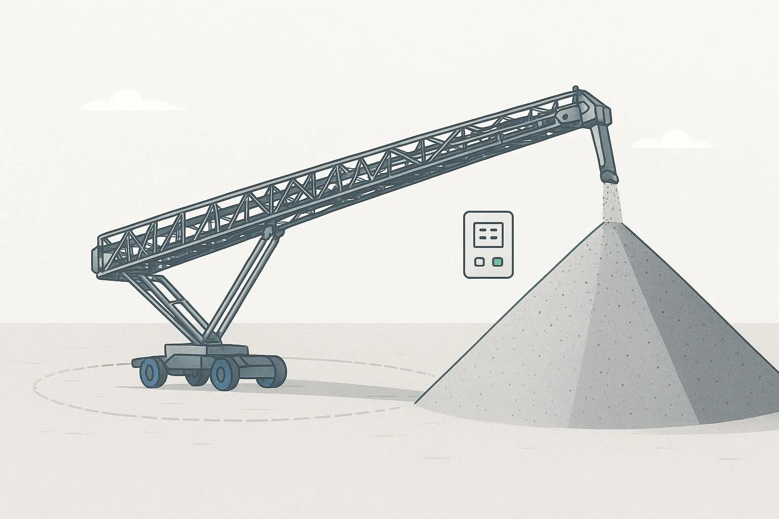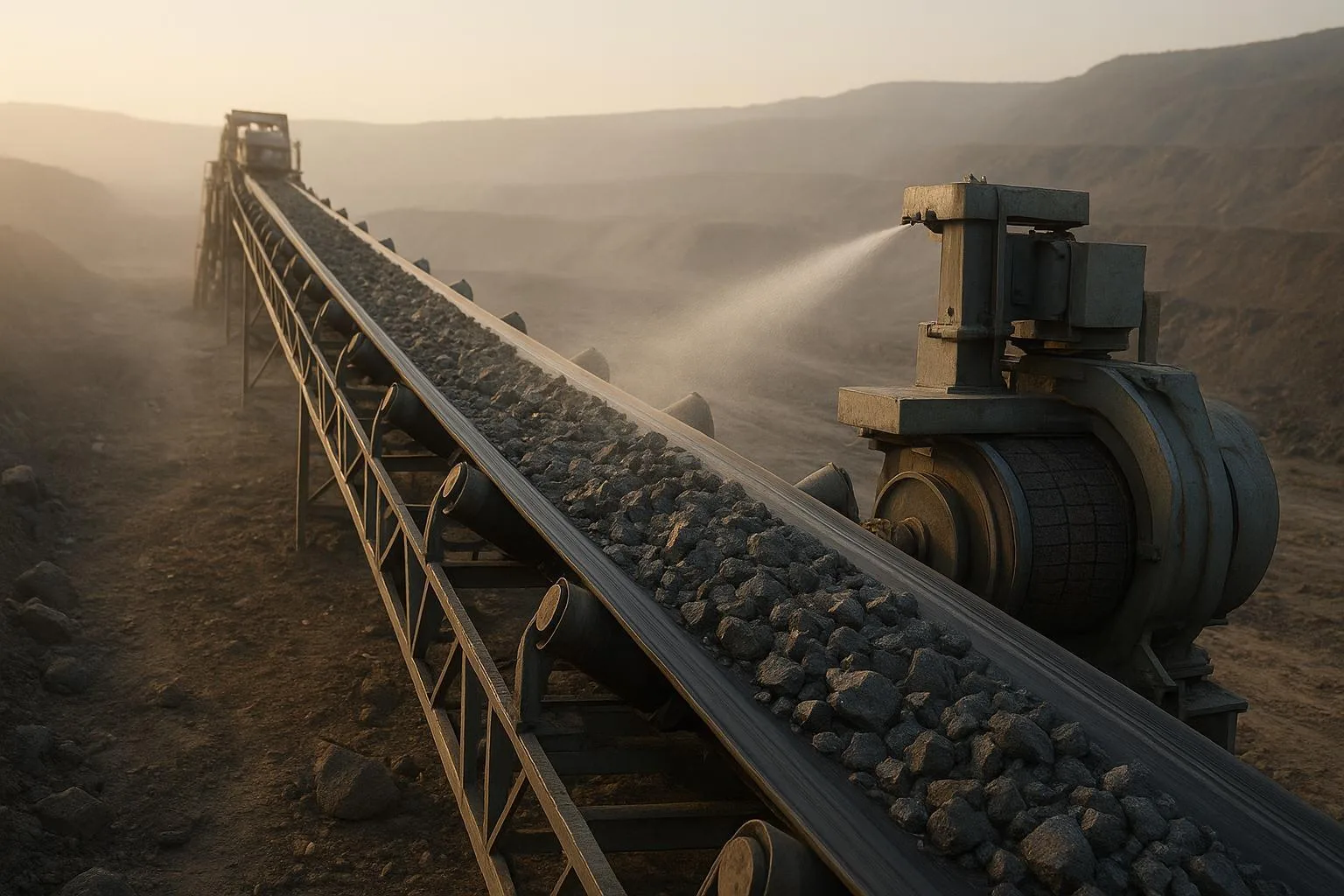
Designing a belt conveyor that runs safely, cleanly, and reliably under harsh conditions is part engineering, part discipline. Done well, it reduces downtime, protects people, and lowers total cost of ownership. Done poorly, it becomes a chronic source of spillage, mistracking, and unplanned stops. This guide captures field-tested advice and standards-aligned methods you can apply across mining, cement, ports, and heavy manufacturing.
Key Takeaways
-
Start with material properties (bulk density, moisture, lump size, abrasiveness) and design for the worst credible case.
-
Follow standards: use CEMA methods for classification and calculations, and apply ISO machine safety requirements for guarding and controls.
-
Size belts, idlers, pulleys, drives, and take-ups as a system, not as standalone parts.
-
Stabilize loading zones and control dust with proper support, skirtboards, and multi-stage belt cleaning.
-
Commission deliberately, monitor condition, and schedule preventive maintenance; troubleshooting becomes faster and cheaper.
Core Concepts for Conveyor System Design Best Practices
The phrase “Conveyor System Design Best Practices” is more than SEO—it’s a reminder to make disciplined, standards-based choices. Below are the core concepts you’ll use on every project.
Material characterization and why it drives everything
Begin by classifying the bulk material per ANSI/CEMA 550 (2020), which defines properties such as bulk density, flowability, and abrasiveness. Using the wrong density or lump-size assumption will skew capacity, tension, and wear predictions. Martin Engineering has shown with examples that coal densities vary widely, underscoring the need to anchor calculations in the correct material class and worst-case properties; see their discussion referencing CEMA 550 in the design pitfalls overview (2021).
Practical notes:
-
Capacity depends on belt cross-sectional area and speed; area is a function of belt width and trough angle.
-
Higher moisture and finer fractions increase carryback and dust potential, influencing cleaner selection and skirt sealing.
For component roles and terminology, the conveyor components guide provides a solid refresher.
Standards, classes, and selection context
Use CEMA classification to select idler classes and dimensional norms; ANSI/CEMA 402 (R-2020) provides belt conveyor dimensional and performance guidance and is accessible via the CEMA ANSI standards page. The CEMA Belt Book (7th Edition, 2nd printing, 2019) remains the widely used reference; CEMA has been developing updates (with Chapter 14 on Operation under review in 2023 per CEMA agenda documents).
Safety is non-negotiable. ISO 14120:2015 defines general requirements for machine guards; ISO 13849-1:2023 governs safety-related control system parts and performance levels. See ISO 14120 (2015) and ISO 13849-1 (2023) for scope and definitions.
Calculations overview: capacity, belt tension, and drive power
Conveyor capacity Q (t/h) is derived from belt cross-sectional area A (m²), belt speed v (m/s), and bulk density ρ (t/m³). CEMA/DIN/ISO methods differ in detail but align conceptually:
-
Running tension sums primary resistances (rolling, flexure), secondary resistances (skirting, plows, cleaners), elevation lift, and correction factors.
-
Starting/acceleration tension exceeds running tension—account for drive torque and take-up design.
-
Modern tools (e.g., Belt Analyst) implement CEMA, DIN 22101, and ISO 5048 methods; see Overland Conveyor’s Belt Analyst for methodology support.
Speed selection is a trade. Very high speeds (7.5–11.5 m/s) are possible but can exacerbate dust and degradation; designers often trade speed versus width for cleanliness and controllability. Martin Engineering’s design pitfalls article (2021) explains the practical limits.
Troughability, idler spacing, and loading-zone stability
Trough angle (typically 35° or 45° for heavy-duty belts) and idler spacing determine cross-section and sag. Reduce spacing in the skirted loading zone; use impact cradles or slider beds to minimize sag and stabilize sealing. Load only after the belt reaches full trough; maintain a free belt edge (~115 mm ≈ 4.5 in) for sealing and mistracking margin. These practices are emphasized in Martin Engineering’s design mistakes and remedies (2021).
Pulley diameter and lagging selection
The smallest pulley with ≥90° wrap is typically the critical diameter to verify. Using an undersized pulley increases bending strain and splice risk; wing (self-cleaning) pulleys often require larger diameters. For lagging:
-
Rubber lagging (plain or diamond) is common for moderate duty; diamond patterns help shed water.
-
Ceramic lagging increases friction and wear life in severe duty drive applications; smooth ceramic is often recommended on non-drive pulleys for cleaner compatibility.
For practical lagging choices and cautions, see Flexco’s Ultimate Flex-Lag Tech Guide (2021) and their quick fixes overview.
Take-up systems: gravity, screw, and hydraulic
A take-up maintains adequate tension at the drive to prevent slip and maintain tracking. Conceptually:
-
Gravity take-ups provide near-constant tension and are suited to long conveyors; they require space and robust guarding.
-
Screw take-ups are compact and cost-effective on short conveyors but need periodic adjustment as belt length changes.
-
Hydraulic take-ups offer controlled tension in compact footprints, at the expense of system complexity.
Because a single citable comparison table wasn’t found in public sources, consult the CEMA Belt Book and OEM manuals for formal selection criteria. Martin Engineering’s practice context on belts provides additional orientation.
Worked micro-calculation: quick tension and power check
Scenario: 900 mm belt, 800 t/h, v = 2.0 m/s, bulk density ρ ≈ 1.6 t/m³ (example crushed ore). Concept steps:
-
Cross-sectional area A: choose trough angle (e.g., 35°) and use belt manufacturer/CEMA tables to find A for a 900 mm belt; suppose A ≈ 0.28 m² (illustrative).
-
Capacity check: Q_calc = A × v × ρ = 0.28 × 2.0 × 1.6 ≈ 0.90 t/s ≈ 3,240 t/h. If the target is 800 t/h, the belt is oversized for capacity, which may be intentional for wear or future growth.
-
Primary resistance: estimate equivalent friction factor f (method-dependent); calculate running power P_run = (Total resistance × belt speed). Use CEMA/DIN/ISO formulas implemented in software for precise numbers.
-
Starting tension: apply a factor over running (e.g., consider acceleration torque and take-up). Verify against splice/belt limits and drive torque.
-
Drive selection: apply service factor consistent with duty (e.g., ≥1.25 for heavy, shock loading). Validate with vendor data and the governing method (CEMA/DIN/ISO).
This “sanity check” helps ensure design margins are plausible before detailed software runs.
Practical Applications and Use Cases
Overland conveyors in mining
Long-distance conveyors often operate around 4.0–4.5 m/s per BEUMER case narratives and commissioning notes; see BEUMER’s bulk materials systems overview and availability case press (press materials 2023–2024). Key practices: stabilize loading zones, proportion width/speed for dust control, and verify take-up travel for temperature and creep effects.
Port ship-loader conveyors
Load dynamics vary; belts may run up to ~7 m/s where permissible. Transfer chutes must manage induced air and prevent carryback onto return idlers. Design head chutes with space for multi-stage cleaners and access.
Cement plant clinker feed
High-temperature resistance, abrasion control, and robust sealing are priorities. Ceramic lagging at the drive and heavy-duty impact idlers under the drop zone are common. Cleaning systems should withstand hot fines without hydroplaning.
Stockpile reclaim conveyors
Expect variable loading; use conservative idler spacing through reclaim hoppers and monitor tracking closely. Dust control and cleanup access determine practical uptime.
Example component selection in practice (BisonConvey)
At a primary crusher feed handling 1,000 t/h granite with high impact, an engineer might specify a steel-cord belt for low elongation, impact idlers or cradles in the loading zone, and ceramic-lagged drive pulleys to reduce slip risk. In projects where suppliers offer consistent heavy-duty components, engineers often source belts, idlers, and pulleys from specialized manufacturers. For an overview of components and terminology, see BisonConvey’s conveyor components guide. This example illustrates how component choices align with duty and material—not a vendor claim of performance.
Selection and Implementation Guidelines
Component selection checklist
-
Belts: width, strength class, elongation, cover compound, splice type, temperature and abrasion resistance.
-
Idlers: class (B–F per CEMA), trough angle, spacing (reduced in loading zone), sealing quality, bearing protection.
-
Pulleys: diameter (critical wrap), face width, lagging type (rubber/ceramic), alignment tolerances.
-
Cleaners: primary/secondary staged, compatibility with belt and lagging; access for maintenance.
-
Skirtboards and sealing: sealing geometry, support beds/cradles, free belt edge margin.
-
Take-up: gravity/screw/hydraulic selection, travel, guarding and access.
-
Drives: power rating, service factor, torque control, soft-start/variable-speed as needed.
-
Controls and safety: e-stop strategy, lockout/tagout, guarding per ISO 14120 and safety PLC/performance level per ISO 13849-1.
Quick comparison tables
Belts: textile vs steel-cord (selection context)
Lagging types: rubber vs ceramic (drive pulley context)
Common Problems and Troubleshooting
Tracking and spillage
Root causes include misaligned structures or pulleys, seized or mis-set idlers, off-center loading, and carryback buildup. Remedies: confirm structure squareness and pulley alignment, balance loading with chute internals, install multi-stage cleaners, replace seized idlers, avoid over-tight skirting. For deeper theory, consult the belt tracking guide.
Dust and carryback
Insufficient cleaning, poor sealing/support at load zones, and flawed chute airflow control are typical culprits. Multi-stage cleaning (primary urethane near 3 o’clock; secondary tungsten near 6 o’clock) and a stabilized loading zone reduce carryback onto return idlers. Martin Engineering’s Foundations articles discuss airflow management and carryback effectiveness; see airflow guidance (knowledge page) and carryback effectiveness study%20Feb,%202020.01.pdf) (2020).
Idler bearing failure and lagging wear
Contamination, misalignment, over-tension, and material buildup drive premature failures. Replace seized idlers promptly, align pulleys, and validate tension. For lagging, verify diameter and friction needs; Flexco’s lagging selection guidance (2021) summarizes pros and cons.
Safety note: every belt cleaner is an in-running nip hazard. Follow lockout/tagout and guarding requirements during service.
Best Practices and Maintenance Tips
Commissioning checks
Commissioning should verify mechanical, electrical, and control functions before production. Large systems often complete staged installation, dry runs, and performance tests over weeks to months; BEUMER’s commissioning services overview describes typical steps. Practical checkpoints:
-
Guarding and access match ISO 14120 scope.
-
E-stop and safety circuits meet ISO 13849-1 performance levels.
-
Belt tracking verified under light and heavy loads; take-up travel confirmed.
-
Cleaner pressure set and access established.
-
Dust control devices installed and reachable for maintenance.
Preventive maintenance and monitoring
Adopt PM frequencies matched to duty rather than fixed hours; use thermal and vibration checks on critical bearings, and schedule proactive replacement of high-wear components. For task-level steps, see the belt replacement procedure and adapt to your site’s LOTO and permit processes.
Spare parts strategy and retrofit notes
-
Stock essential spares (idlers, cleaner blades, splice kits, belt fasteners where applicable, lagging tiles for drive pulleys).
-
Consider retrofits where dust or wear persists: engineered chutes, impact cradles, or upgraded cleaners.
-
Document changes and their effect on uptime and cleanup hours; this builds your ROI case.
Conclusion: Turning principles into uptime
“Conveyor System Design Best Practices” means engineering the whole system—material, mechanics, safety, and maintenance—so it stays stable under real-world loads. Start with accurate material data, select components by standards, stabilize the loading zone, and commission deliberately. Keep PM tight and troubleshooting disciplined, and your conveyor will repay you in uptime.
Next steps: if you need guidance on belts, idlers, or pulleys for severe duty, review the engineering resources at BisonConvey and contact the team for component selection support tailored to your application.