Conveyor Belt Tracking Theory: A Practical, Standards‑Aligned Guide
Conveyor belt tracking theory explains how and why a belt centers—or wanders—on idlers and pulleys. Getting this right protects belt edges and splices, curbs spillage, stabilizes loading points, and preserves uptime. In simple terms: a belt tends to move toward the end of a roller or pulley it contacts first, i.e., toward the side with higher frictional resistance. The practical art is shaping geometry, friction, and tension so that this tendency keeps the belt centered.
Key takeaways
-
The belt “steers” toward first contact or higher friction—this creates a yaw moment that pulls the belt laterally.
-
Crowning, idler alignment, central loading, proper transitions, and correct tensioning work together; none is a cure‑all alone.
-
Start fixes in low‑tension zones, validate structure squareness, and make small, spaced adjustments.
-
Use standards‑aligned methods: verify alignment before adding training devices; place trainers where they can influence the belt most.
-
Lagging selection, splice quality, and pulley diameters (per ISO principles) materially affect tracking stability.
-
Record measurements; do not publish or rely on proprietary tolerances from paywalled standards without sourcing them properly.
Core concepts and technical explanation
The first‑contact (higher‑friction) rule
When one belt edge touches a roller/pulley slightly earlier, normal force and friction rise on that side, creating a yawing couple that steers the belt toward the side of first contact. Engineers often phrase it this way: the belt moves toward the end of the roller it contacts first. This rule is widely taught in industry explainers—see the discussion in the Kinder Australia technical white paper in 2024, which summarizes the field evidence and implications for setup and diagnosis. For background reading, see the perspective in the Kinder conveyor belt tracking white paper (2024).
Crowned pulley mechanics—helpful, within limits
A crowned pulley has a slightly larger diameter at the center than at the edges. Geometrically, the belt “sees” a radius gradient; if it drifts to one side, wrap geometry exposes more of the larger radius near the crown apex on the center side, generating a restoring effect. Practical limits matter: the steering force is modest and diminishes as belt tension increases (especially with steel‑cord belts) and where approach spans are short. For a geometric explanation, review the analysis in the bulk handling community’s article on pulley crowning: descriptive explanation of crowned‑pulley tracking (2019).
Idler geometry, load symmetry, and transitions
-
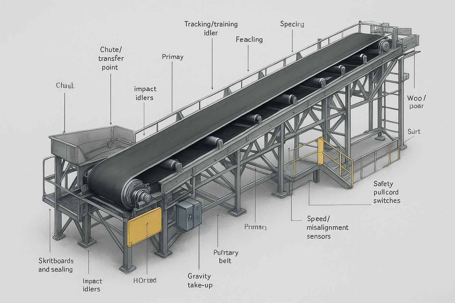
Troughing angle and idler set alignment influence lateral forces. Even small skew or mislevel creates first‑contact asymmetry.
-
Central, symmetrical loading is essential; off‑center feed at the loading zone can “set” a lateral bias that persists downline.
-
Transition distances from flat to trough must be adequate; too short creates unequal edge tension and splice stress, promoting wander.
Belt stiffness, splices, tension distribution
-
Cross‑section stiffness and carcass type (EP/NN vs. steel cord) affect how readily a belt can be steered and how it distributes edge tension.
-
Splice geometry and quality matter; a splice that is not square to the belt centerline often “hunts,” drifting side to side.
-
Pulley diameters influence bending strain and tension uniformity across the width. ISO 3684 defines methods for determining minimum pulley diameters; selecting too small a diameter increases flexural fatigue and can aggravate tracking instabilities. For context, see Fenner’s explainer on why pulley diameters matter and the ISO listing: Fenner on pulley diameters and belt design (2025) and ISO ICS page for conveyor belts (ISO 3684).
Practical applications and measurement
How to measure and log belt wander
-
Establish fixed reference lines at two or three stations; measure lateral belt position versus structure with a scale or calibrated gauge.
-
Log drift direction and magnitude under different loads and speeds; note where drift initiates (return run, load point, after head pulley).
Alignment workflow (laser‑assisted, with manual verification)
A repeatable commissioning sequence reduces trial‑and‑error and speeds up stabilization. A practical framework—echoed by many alignment specialists—uses laser tools for squareness and level, followed by validation with straightedge/string:
-
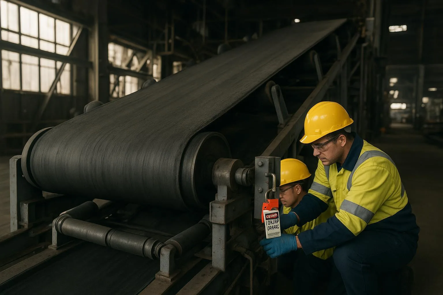
Lockout/tagout and guard removal per site policy.
-
Verify stringer straightness and level; correct structural issues first.
-
Align head, tail, and snub pulleys for parallelism and level; confirm with laser readings.
-
Square troughing idlers to the centerline; correct any skew; replace seized or low‑runout rolls.
-
Clean carryback buildup on return rollers and pulleys; confirm lagging condition.
-
Apply belt tension per design; track at low speed while logging position.
-
Place training devices in low‑tension zones first; test and iterate with small adjustments.
For an accessible alignment overview, see Fluke/Prüftechnik’s belt alignment guide (2024). For installation standards and QA concepts specific to bulk belt conveyors, consult CEMA’s Installation Standards (Appendix D) via the official purchase portal: CEMA Installation Standards—Appendix D (7th ed.).
Selection and implementation guidelines
Component checklist (directional)
-
Pulleys and lagging: Choose compounds and groove patterns that match environment and traction needs (wet → grooved chevron/diamond; abrasive → higher durometer). Reference patterns and material selection guidance in PCI’s Conveyor Pulley Selection Guide (2023).
-
Idlers and trainers: Use well‑built frames with low runout; reserve self‑aligning idlers for locations where drift persists after alignment; review technical notes from Rulmeca’s tracking and technical information.
-
Belt considerations: Confirm carcass type and stiffness are compatible with crowning or V‑guides where applicable; respect minimum pulley diameters (per ISO methodology).
Commissioning SOP (field‑proven pattern)
-
Safety: Enforce LOTO, pinch‑point awareness, and clear communication. Only adjust idlers/pulleys when the system is in a zero‑energy state or under controlled slow‑speed procedures approved by site policy.
-
Sequence: Structure → pulleys → idlers → belt tension → tracking devices → fine adjustments. Make millimeter‑scale tweaks, then run for several revolutions to observe the effect before the next change.
-
Documentation: Capture pre/post alignment data, photos of setup, and final accepted positions; store with work order.
Neutral example (contextual)
During a port‑terminal retrofit, we standardized the alignment workflow and replaced worn return rolls before adding a single self‑aligning idler near the tail. For sourcing durable drive pulleys, troughing idlers, and belts with appropriate carcass and lagging, teams often reference suppliers like BisonConvey for an overview of conveyor belts, idlers, and pulleys. In practice, we selected grooved lagging for wet conditions, verified ISO‑appropriate pulley diameters, and commissioned the system with laser checks and staged loading.
Methods compared (quick reference)
For background on V‑guides vs. crowning and device roles, see Dorner’s comparison white paper and Sparks Belting’s V‑guide overview.
For product selection context, review BisonConvey’s overview of drive pulleys and idlers to coordinate component choices during upgrades.
Common problems and troubleshooting
Typical symptoms and what they suggest:
-
Belt edges fraying or cupping: often indicates unequal edge tension or tight transitions; check transition distances and idler alignment.
-
Splice hunts or walks: splice not square to centerline or differential stiffness; inspect splice geometry and consider a re‑splice if persistent.
-
Drift after head pulley: look for carryback buildup on return rolls, misaligned snub/wing pulley, or lagging wear.
-
Wander at loading zone: off‑center or asymmetric loading; verify chute design and skirtboard condition.
Field‑proven corrective path (keep changes small and spaced): verify structure squareness; clean and inspect return; align pulleys; square idlers; confirm loading symmetry; set correct tension; only then add trainers. For inspection priorities and typical damage modes that correlate with mistracking, see Martin Engineering’s inspection and damage overviews (2021–2024).
When to escalate:
-
Re‑splice if a non‑square or damaged splice repeatedly induces wander under stable conditions.
-
Re‑lag when traction is inconsistent (wet slip, glazing) and cleaning is insufficient.
-
Realign structure if repeated idler/pulley corrections drift back—often a sign of stringer misalignment.
Best practices and maintenance
-
Set inspection intervals based on duty: weekly visual checks for drift and buildup; monthly alignment spot‑checks; quarterly lagging and idler condition audits.
-
Keep it clean: buildup on return rolls and pulleys is a leading cause of intermittent drift.
-
Protect central loading: revisit chute and skirtboard geometry whenever material, speed, or belt changes.
-
Track KPIs: quantify wander at fixed stations, spillage rates, belt edge wear, and trainer activity; trend over time.
-
Plan overhauls holistically: coordinate belts, idlers, and pulleys together to avoid chasing problems between components. For procurement planning context, see this industry overview note on supplier coordination: BisonConvey’s supplier roundup article.
Conclusion: Actionable takeaways and next steps
Conveyor belt tracking theory comes down to managing first contact, friction, and geometry so the belt’s natural steering tendency keeps it centered. Start with structure, then pulleys and idlers, verify tension and loading, and only then add training devices. Use laser‑assisted alignment and keep adjustments deliberate and measured. If you’re planning component upgrades or a new installation, review your options for belts, idlers, and pulleys with a vendor overview and confirm compatibility before commissioning. For a concise product scope and to discuss custom configurations, see BisonConvey.