Title: Conveyor Belt Skirting: Functionality & Importance Meta description: Engineer’s guide to conveyor skirting—design, materials, installation tolerances, troubleshooting, and maintenance best practices.
Conveyor Belt Skirting: Functionality and Importance
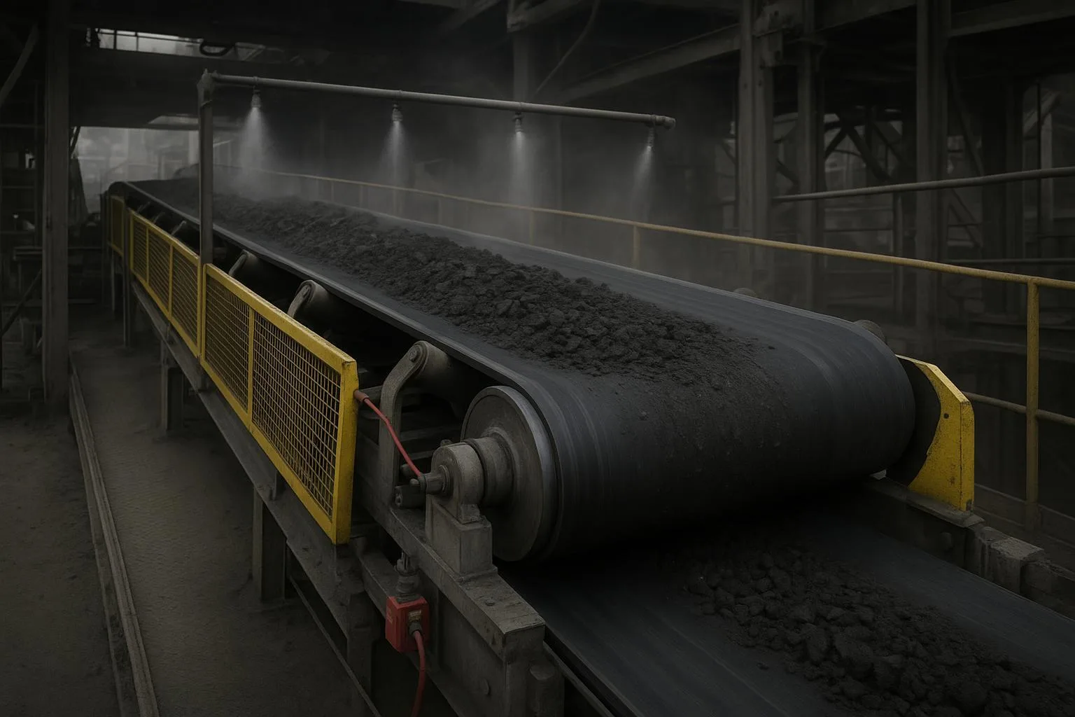
Conveyor belt skirting is a flexible sealing element mounted along skirtboards at loading and transfer points. Its job is simple but critical: keep bulk material and fines on the belt while minimizing dust escape. Done well, skirting protects uptime, reduces housekeeping, and extends belt and liner life. Done poorly, it grooves belt edges, increases drag, and turns transfer points into constant maintenance hotspots.
Key decision-makers—plant engineers, reliability leads, and procurement—typically want three things from a skirting system: predictable sealing, low wear, and easy adjustment. This guide delivers a practical, standards-aware approach to achieve exactly that.
Core concepts of Conveyor Belt Skirting: Functionality and Importance
What the skirt and skirtboards actually do
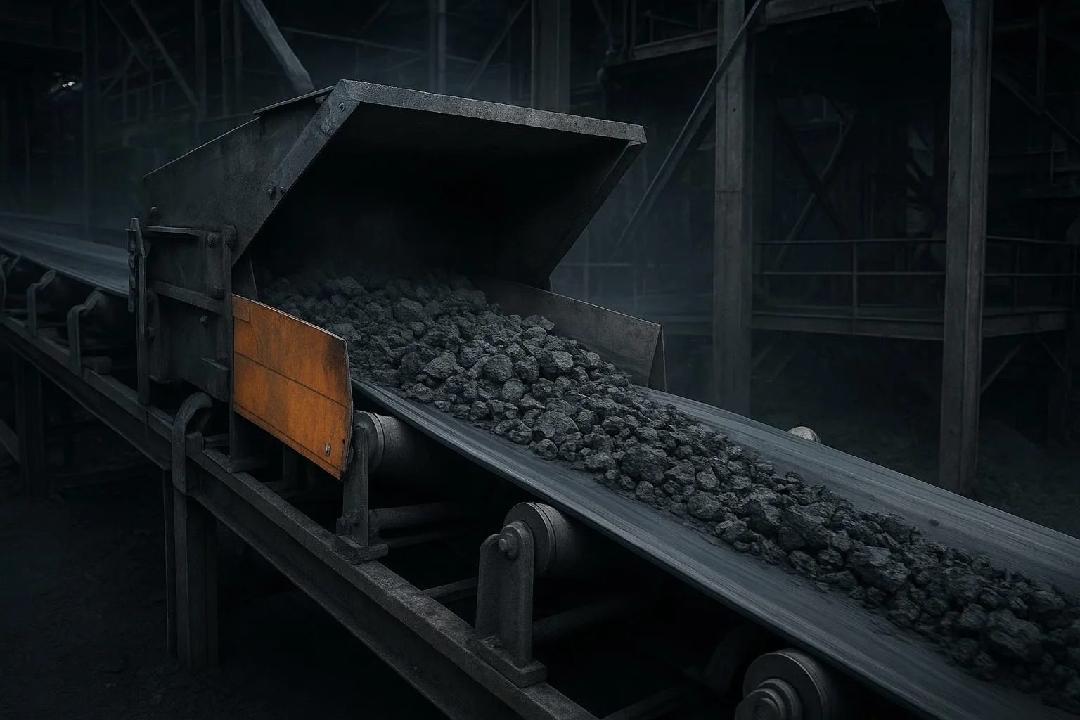
Skirting is the flexible seal that lightly bears on the belt edge to close the gap between the moving belt and the stationary skirtboards. The skirtboards define the load zone geometry and, with the wear liner, contain the burden. A healthy system lets the liner and chute manage impact and flow while the skirt prevents fines and air from leaking out along the edges.
According to public summaries of CEMA committee guidance and widely cited best practices, leaving adequate free belt edge per side is essential so the seal can work without riding into conveyed material. Martin Engineering’s Foundations content emphasizes starting loading only after the belt reaches full trough, which stabilizes the profile and reduces entrapment risk at the seal line, as discussed in the design notes on belt stability and transfer points from the Foundations library.
- Reference: See the belt stability note in Martin Engineering’s knowledge base on conveyor support and troughing: belt stability and support guidance. Also see the broader design note on avoiding common specification mistakes: ten common mistakes in conveyor design.
Components that make a seal work
A reliable loading zone usually includes:
-
Skirt seal strips (rubber or polyurethane) clamped to the skirtboards
-
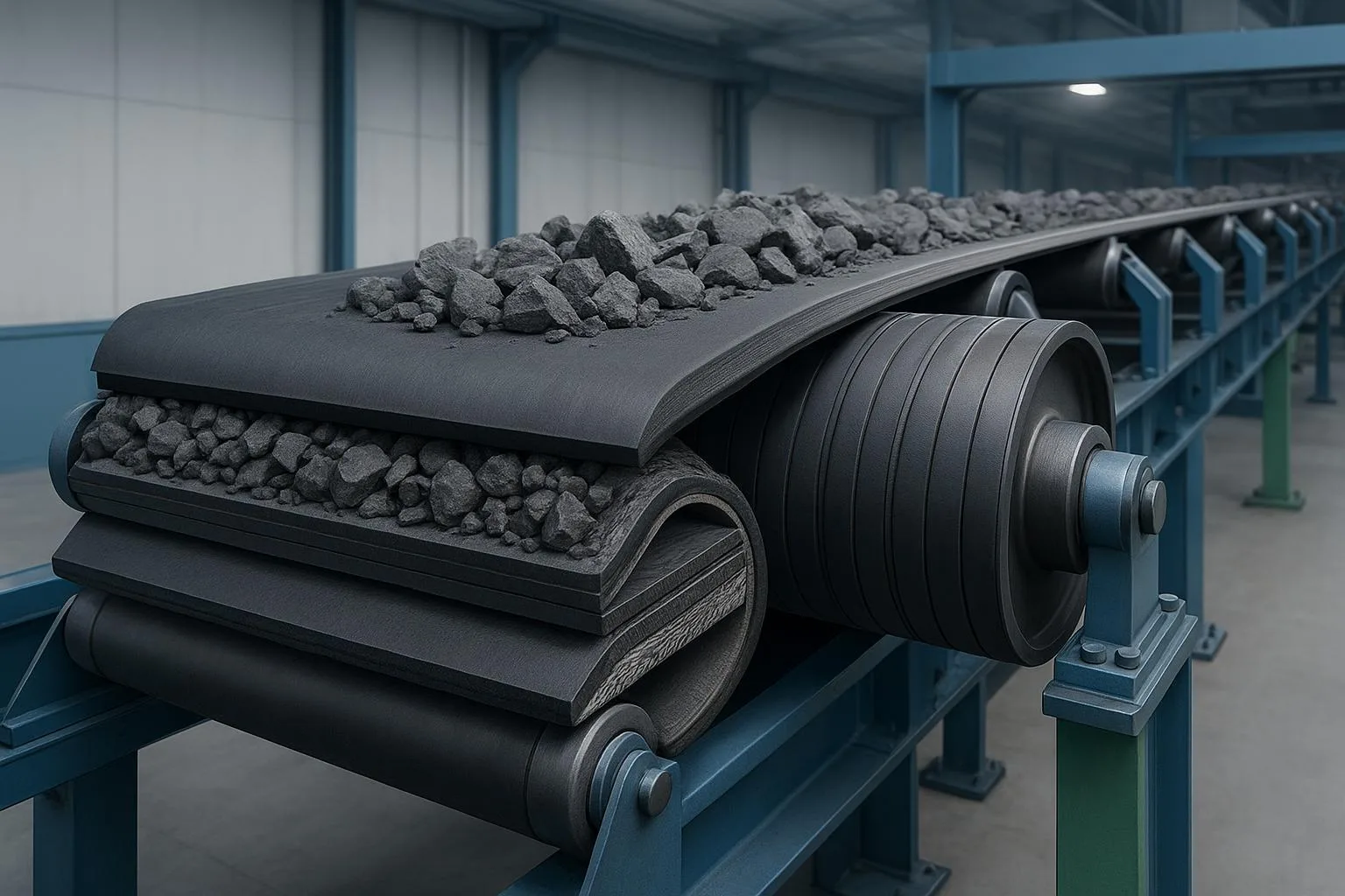
Wear liners inside the chute to carry the burden and shield seals from direct impact
-
Adjustable clamps that allow precise, incremental pressure settings
-
Impact beds or closely spaced idlers to create a flat, sag-free belt line under the seal
-
Dust curtains to reduce openings and slow air at entrances/exits
Each component has a distinct role. If the liner is worn away or the belt sags, the skirt starts behaving like a retaining device, which spikes drag and wear.
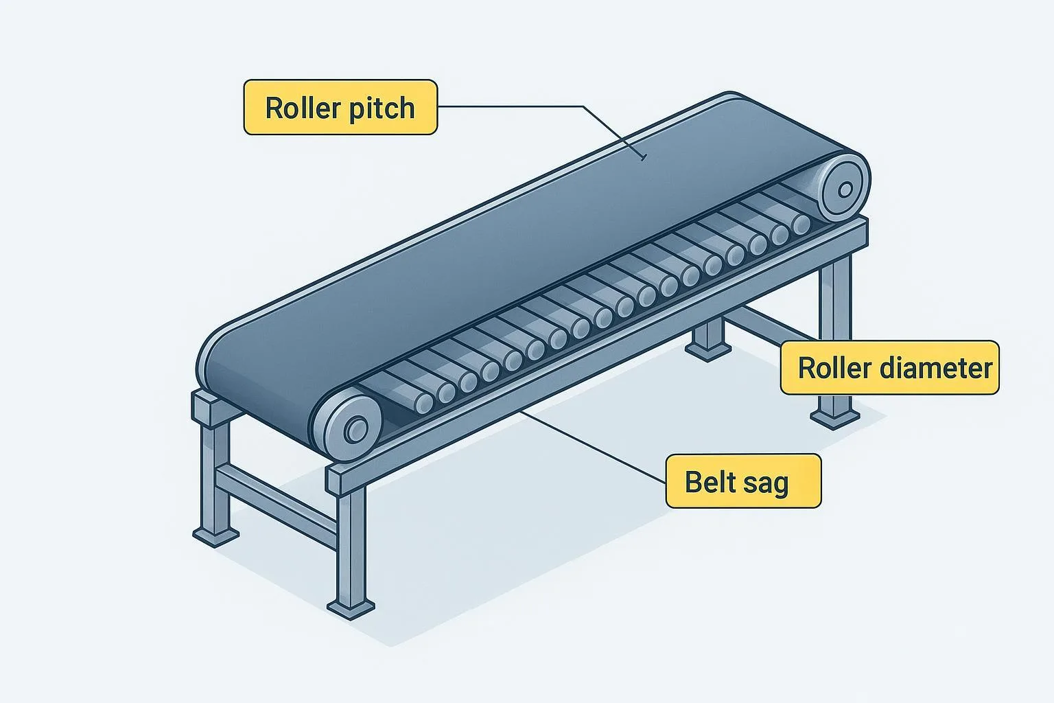
Why belt support and troughing matter
Seals don’t compensate for poor support. A belt that sags between idlers forms a wavy surface that alternately opens gaps and pinches the seal. Using impact cradles under the drop zone and closely spaced idlers along the skirted section maintains a flat, consistent surface, which is the foundation for a light-pressure, low-drag seal. For context and design rationale, see Martin’s support article: belt support in the loading zone%20July-Aug,%202024.01.pdf).
Design and selection principles
Sizing the seal and skirtboard (free edge, width, and length)
Use these typical, field-proven heuristics as a starting point, then refine for your material, speed, and support scheme:
-
Free belt edge allowance: Reserve about 115 mm (4.5 in) per side to cover both sealing width and expected wander; adjust upward for five-roll catenary idlers or known mistracking. This allowance concept and practice are reiterated in CEMA Accessories Committee public agenda sets: 2018 committee agenda set and 2019 committee agenda set.
-
Skirtboard spacing vs. belt width: Set the distance between skirtboards to roughly two-thirds of the troughed belt width; verify that the resulting free edge still meets your allowance (CEMA committee notes as above).
-
Minimum skirtboard/settling length: A practical rule is about 2 ft per 100 fpm of belt speed with a minimum of 3 ft. See the CEMA Belt Book first-printing change pages that restate this heuristic: CEMA change pages excerpt.
-
Start loading after the first full-trough idler to avoid forcing seals to follow a changing belt profile. This practice is reinforced in Martin’s design notes: common mistakes in conveyor specification.
Choosing materials for skirt seals
Different compounds trade off abrasion resistance, temperature capability, and chemical/weather resistance. The table below summarizes typical published ranges and use cases. Always check the specific datasheet for the compound you purchase.
Representative sources for these ranges and properties include vendor and catalog pages such as Walker Rubber’s EPDM knowledge hub, Coruba’s NR/SBR skirting sheets, and Argonics’ polyurethane product guides: EPDM properties overview, NR/SBR skirting sheet example, and Argonics polyurethane overview.
Environmental and operational constraints
-
Temperature: Select compounds that match ambient and material temperatures. High-temperature clinker demands EPDM or specialized PU; cold-weather mines may favor NR grades designed for low-temperature resilience.
-
Moisture and chemistry: EPDM provides strong resistance to water, steam, and many chemicals; NR/SBR and PU handle abrasion well but check compatibility with oils/solvents.
-
Material abrasiveness and lump size: PU generally outlasts rubber in severe abrasion/impact; ceramic-reinforced liners inside the chute can protect seals from direct impact.
-
Belt speed and support: Faster belts and deeper troughs drive longer skirt lengths and tighter support spacing to maintain a flat seal interface.
Installation and commissioning — conveyor skirting installation best practices
Quick installation checklist with tolerances
Use this practical list to set up a low-drag, long-life seal. Values below reflect typical manufacturer IOMs for standard skirting systems.
-
Verify belt support: Install impact beds under the drop zone and closely spaced idlers through the skirted length to achieve a flat belt line.
-
Set skirtboards square/level: Space them to about two-thirds of troughed width and confirm free-edge allowance per side.
-
Position the wear liner: Ensure clearance to the belt is constant or increasing in the direction of belt travel.
-
Initial clearances: Aim for ~1/8 in (≈3 mm) empty-belt clearance at the tail/load point and ≤1/2 in (≈13 mm) at the discharge end. See Flexco’s IOM for representative values: standard skirting IOM.
-
Clamp and adjust: Bring the seal into light, uniform contact—enough to close gaps without pinching. Tighten clamps gradually and evenly.
-
Run-in: Operate for ~15 minutes, then shut down and recheck tracking, clearances, drag/heat, and dusting. Re-adjust in small increments. Reference: updated Flexco IOM (international).
-
Enclosure airflow: Fit strip curtains at openings and size local exhaust to keep exit air velocities in the ~200–250 fpm range per NIOSH: NIOSH Dust Control Handbook (2019).
Common installation mistakes and how to avoid them
-
Using the skirt as a retaining device: Replace/realign worn liners so the seal stops sealing the burden itself.
-
Inadequate free edge: If the burden rides into the seal, increase free-edge distance or adjust skirtboard spacing.
-
Belt sag under the seal: Add/renew impact cradles or reduce idler spacing to flatten the belt line.
-
Over-tight clamps: Excess pressure accelerates wear and can groove the belt. Back off to light, uniform contact.
Acceptance checks and early adjustments
During commissioning, look and listen. A properly set seal is quiet, runs cool, and shows a thin, uniform polishing track on the belt edge after the first shift. Dust escaping from joints or ends suggests gaps or excessive induced air; spillage at the skirt ends often points to insufficient skirt length or missing curtains. Make incremental adjustments only—heavy-handed changes usually trade one problem for another.
Maintenance and troubleshooting
Routine inspection intervals and what to measure
-
Daily/shiftly: Walk-by check for dust plumes, unusual noise/heat, and spillage at ends. Spot-check clamp tightness.
-
Weekly: Measure skirt protrusion and contact band; inspect wear liner condition and belt edge for any grooving.
-
Monthly/quarterly: Verify free-edge allowance, idler/impact bed condition, and curtain integrity; confirm enclosure airflow still meets targets.
Troubleshooting: symptoms, likely causes, corrective actions
For failure modes related to entrapment and grooving, see Martin’s guidance on avoiding belt entrapment damage: belt entrapment damage overview.
Practical use cases and examples
Abrasive ore service (iron ore, copper)
In high-abrasion duties, polyurethane skirts paired with ceramic-reinforced wear liners inside the chute typically extend service intervals compared with NR/SBR skirts in the same setting. The belt must be well supported—impact cradles at the drop zone and tight idler spacing through the seal area—to prevent entrapment that can still cut a groove even with PU.
High-moisture limestone or fertilizer
Where materials carry moisture and may smear, EPDM offers weather and steam resistance, while PU provides wear life on the contact band. Keep contact pressure light to discourage paste build-up under the seal. Curtains at entrances help calm entrained air so fines settle in the skirted length rather than at the exit.
Micro-example: matching support hardware to reduce skirt wear
On a retrofitted quarry conveyor, moving from three-roll troughing with wide spacing to a short impact cradle under the drop zone plus closely spaced idlers through the skirted segment flattened the belt line and reduced skirt adjustments from weekly to monthly. When planning such changes, engineering calculators help verify the impacts on load-zone length, capacity, and idler spacing. A practical starting point is the set of neutral conveyor engineering tools from BisonConvey for quick checks on belt capacity and geometry.
Standards, safety, and environmental context
Applying CEMA public notes in practice
Publicly available CEMA Accessories Committee agenda sets reiterate typical practices that designers can adopt without reproducing paywalled tables: keep skirtboard spacing to roughly two-thirds of troughed width, specify free-belt edge explicitly (seal width + expected wander), and size skirt length to about 2 ft per 100 fpm with a practical minimum. Committee change pages also reference minimum uncovered skirtboard heights. See examples here: 2017 agenda set and change pages excerpt.
For design stability, Martin Engineering’s Foundations material advises beginning loading only after the first full-trough idler and ensuring the belt is flat and well supported through the skirted section: Foundations chapter excerpt on conventional transfer chutes.
ISO machinery safety mapping
There is no ISO standard dedicated solely to skirting. However, skirting, guards, and enclosures fall under machinery safety frameworks used during risk assessment:
-
ISO 12100 (risk assessment and risk reduction) helps structure hazard identification and risk controls around the transfer point. See the standard overview: ISO 12100 summary.
-
ISO 14120 (guards) and ISO 14119 (interlocking devices) apply where fixed or movable guards are integrated with the loading zone. Overview: ISO 14120 database entry.
-
ISO 14890 (conveyor belt covers) informs belt-cover material properties that interact with seal friction and wear.
Dust-control targets and enclosure strategy
The NIOSH Dust Control Handbook outlines typical enclosure airflow targets around 200 ft/min intake and about 250 ft/min exit velocities at transfer points. Combine that with strip curtains at openings and tight sealing along skirtboards to reduce entrainment. Where site measurements show persistent dust, supplement containment with suppression or local exhaust, sized to those velocity ranges and verified by field readings. Reference: NIOSH Dust Control Handbook (2019).
Actionable wrap-up and next steps
Conveyor belt skirting may look like a small accessory, but its impact on reliability is disproportionate. Treat it as a seal working atop proper support and liners—not as a retention device—and many headaches disappear. Here’s the short checklist to carry forward:
-
Reserve sufficient free belt edge per side and confirm skirt spacing.
-
Keep the belt flat under the seal with impact beds and close idler spacing.
-
Set light, uniform contact; verify 1/8 in tail and ≤1/2 in discharge clearances on an empty belt.
-
Extend the skirted zone long enough for material to settle; use curtains to calm air.
-
Commission with a run-in, then adjust incrementally; maintain with short, regular inspections.
If you need component compatibility checks or quick sizing calculations, you can start with neutral, calculation-first resources like the conveyor engineering tools. For projects that require custom component selection and dimensioning, contact BisonConvey for an engineering review and fit-for-duty recommendations.
References (selected, inline): CEMA Accessories Committee public agenda sets (2017–2019), CEMA change pages on skirt length, Martin Engineering Foundations and transfer-point notes, Flexco skirting IOMs (clearances/run-in), and NIOSH Dust Control Handbook airflow targets. Where specific numeric ranges are mentioned, consider them typical starting values and verify against your system’s conditions.