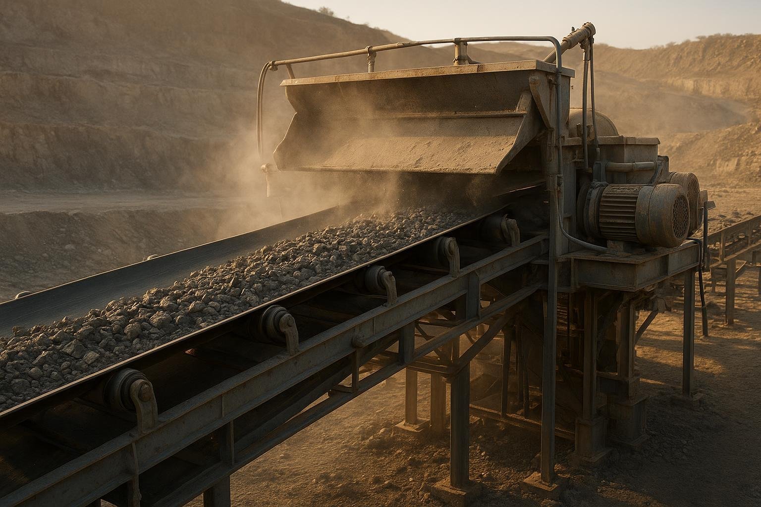
If you need a defensible, low-maintenance conveyor belt spec, start here. This guide walks procurement teams and reliability engineers through a clear, standards-aligned process to choose the right belt for mining, cement, ports, steel, power, and agriculture.
You’ll capture the right inputs, size width and speed correctly, pick the proper carcass and cover compound, and verify component compatibility—without relying on guesswork or one-off anecdotes. We’ll reference CEMA methodology, DIN/ISO concepts, and reputable industry explainers so your choices stand up in design reviews and on the plant floor.
No hype—just a practical workflow with two worked examples and field-proven tips. Let’s dig in.
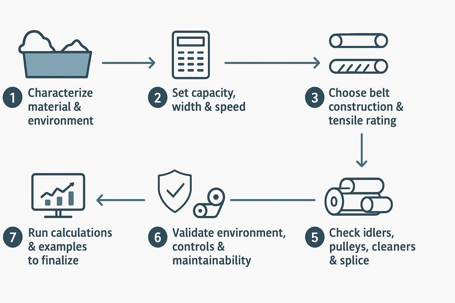
The 7-step workflow for conveyor belt selection for bulk materials (quick view)
- Characterize your material and operating environment.
- Set capacity, belt width, and speed.
- Choose belt construction and tensile rating.
- Specify cover compound and thickness.
- Check idlers, pulleys, cleaners, and splicing.
- Validate environment, controls, and maintainability.
- Run the numbers and finalize with worked examples.
Step 1 — Characterize your material and environment
Start with facts, not assumptions. Document:
- Bulk density (ρ) and moisture; particle size distribution and maximum lump size; abrasiveness (if available, ISO 4649/DIN abrasion figures from lab tests);
- Oil/chemical presence and stickiness; friability (will it degrade at higher speeds?);
- Continuous and peak material/belt surface temperatures;
- Fire and antistatic requirements (e.g., ISO 284 conductivity);
- Drop height and expected impact energy at the loading zone.
Safety and compliance checkpoint:
- Underground coal in the U.S. requires MSHA 30 CFR Part 14 flame-resistant belts; for above-ground combustible dust environments (e.g., grain), apply EN 12882 categories and antistatic per ISO 284. According to the independent reference hub’s overview of underground belt safety and MSHA Part 14 and MSHA program materials, these classifications define ignition resistance, surface resistance, and drum friction behaviors with distinct test methods.
Step 2 — Set capacity, belt width, and speed
Use CEMA-style calculations to size the cross-sectional area based on your trough angle (common three-roll angles: 20°, 35°, 45°) and surcharge angle. Many designers target about 80–85% of theoretical full cross-section to allow for surge, mistracking, and dust control needs. Width follows from required area at the selected speed. For methodology and definitions, see CEMA’s Belt Conveyors for Bulk Materials (publisher landing) and the Martin Engineering Foundations summaries, including their guidance on skirtboard proportions and free belt edge.
Speed selection: bulk belts commonly operate around 0.5–10 m/s (≈100–2000 fpm). Finer, free-flowing materials can run faster; large, abrasive lumps and friable solids benefit from slower speeds (often ≤5 m/s) to reduce wear, spillage, and degradation. Industry knowledge bases also note that cleaner ratings and pulley diameters can limit maximum practical speeds; verify those limits during selection as discussed in Martin Engineering’s danger-zone and cleaner-sizing materials.
Transfer and sealing geometry:
- Keep adequate free belt edge under skirts. A widely cited practice is using skirtboard width at roughly two-thirds of the troughed belt width and maintaining at least ~115 mm (~4.5 in) of free edge on each side to accommodate sealing and minor mistracking, as explained in Martin Engineering’s skirtboard width guidance.
Step 3 — Choose belt construction and tensile rating
Carcass type:
- EP/NN fabric belts suit short-to-medium conveyors, plant services, and moderate tensions with easier splicing and lower cost.
- Steel-cord (ST) belts excel on long-distance, high-tension, or high-speed conveyors due to low elongation and high splice efficiencies when properly manufactured.
Tensile rating and safety factor:
- Standards take different approaches but lead to similar discipline: limit operating tensions to a conservative fraction of rated strength and consider splice efficiency. DIN 22101 historically references an ≈8:1 basis between rated working tension and ultimate strength; common steady-state factors for fabric belts in practice land around 6.7–10 when accounting for splices. Documented projects for modern steel-cord conveyors often achieve effective factors ≈5–8 when splice efficiencies are validated and friction conditions are well controlled. Always verify against current standards, manufacturer tables, and your site risk posture. The ConveyorBeltGuide glossary on safety factors consolidates these definitions and typical ranges.
Practical tip: When in doubt, favor a rating that supports larger pulleys and gentler transitions—small pulley diameters are frequent culprits in splice fatigue.
Step 4 — Specify cover compound and thickness
Map your material and environment to the cover:
- Abrasion: For ores/aggregate, select abrasion-resistant compounds (ARPM/RMA context: Grade I for severe abrasion) and specify sufficient top cover thickness (e.g., 6+3 mm up to 10+4 mm in severe duty) to absorb wear.
- Heat: Choose heat-resistant classes aligned with continuous and peak exposure. Industry references describe ranges commonly labeled T125/T150/T200/T400; align your spec with continuous temperature first, then ensure short-peak tolerance. See Dunlop’s explainer on heat-resistant cover grades for OEM-class descriptions and typical ranges.
- Oil/chemicals: Oils and fats (fertilizers, soy/rapeseed byproducts) require MOR/OR-type oil-resistant compounds to prevent swelling and strength loss.
- Fire/antistatic: For above-ground facilities with combustible dust, apply EN 12882 classes and ISO 284 antistatic; for underground coal in the U.S., specify MSHA Part 14 approved belts.
Right-size thickness:
- Heavier top covers improve wear life under abrasion and impact but add weight and power draw. Balance cover thickness with idler spacing, drop height, and impact-bed design.
Step 5 — Check idlers, pulleys, cleaners, and splicing
Idlers and troughing:
- Common three-roll trough angles: 20°, 35°, 45°. Outside the loading zone, carrying idler spacing often falls around 0.9–2.0 m; in skirted loading zones, tighten spacing to roughly 0.3–0.8 m to control sag and seal integrity. Return idlers are commonly spaced near 3 m, adjusted for belt weight and stiffness. Martin Engineering’s Foundations materials provide detailed context and illustrations.
Minimum pulley diameter (representative checks):
- Minimum diameters depend on carcass type, rating, thickness, and splice. As indicative values published in engineering summaries show, fabric belts scale with carcass thickness (example methods yield head pulleys on the order of ~800 mm for heavy-duty EP constructions), while steel-cord belts step up by rating: representative unlagged minimums include about 800 mm for ST 630, ~1000 mm for ST 1000, ~1250 mm for ST 1600–2000, ~1400 mm for ST 2500, ~1600 mm for ST 3150–3500, ~1800 mm for ST 4000–4500, and ~2000 mm for ST 5000+. For consolidated tables and methodology notes, see the ConveyorBeltGuide engineering page on minimum pulley diameters and then confirm with your belt maker for the exact construction and splice.
Cleaners, lagging, and splice compatibility:
- Blade selection and cleaner count must match belt width, speed, and splice type; some mechanical fasteners restrict cleaner use or require special blades. Drive pulleys in abrasive, wet service often benefit from ceramic lagging to reduce slip and wear. Hot-vulcanized splices are preferred for permanent service at higher tensions/speeds; mechanical fasteners shine for temporary work or where vulcanization is impractical, but they typically require larger pulleys and impose speed limits. For speed/compatibility constraints, consult cleaner and fastener handbooks from vendors such as Flexco (publisher catalog pages).
Step 6 — Validate environment, controls, and maintainability
- Dust suppression (fogging/spray), proper skirtboard and sealing design, and well-positioned cleaners reduce carryback and emissions. Martin Engineering’s dust management chapters provide practical tactics and acceptance checks.
- Tracking aids (self-aligning idlers, training devices) mitigate edge damage; ensure transitions and loading are square to avoid chronic mistracking.
- Provide safe access for inspection and replacement of cleaners, idlers, and skirts; design for lockout/tagout.
- Consider life-cycle energy: low rolling-resistance idlers and optimized tension/transition geometry can reduce power draw.
Step 7 — Worked examples to finalize the spec
These simplified examples show the decision path. Treat numbers as typical, not prescriptive. Use your site’s data and consult standards/manufacturer tables before finalizing.
Example A — EP fabric belt for an aggregate plant conveyor
- Duty: 800 tph crushed aggregate, bulk density ρ ≈ 1.6 t/m³, moderate abrasion, ambient temperature, max lump ~150 mm, conveyor length 180 m, 35° trough, conventional chutes.
- Speed and width: To limit degradation and dust, target v ≈ 2.5–3.0 m/s. At 2.7 m/s, capacity target 800 tph → volumetric flow ≈ 0.5 m³/s. For a 35° trough, select a belt width whose cross-sectional area at ~85% loading supports ~0.5 m³/s at 2.7 m/s (this typically lands in the 800–1000 mm width class; confirm via CEMA cross-section calculations). Assume 900 mm selected after check.
- Carcass and rating: EP fabric belt appropriate. Compute tensions per CEMA/DIN; suppose steady-state max operating tension requires ~EP 800/4 (illustrative). Apply a conservative factor consistent with splice efficiency; confirm transitions and take-up.
- Covers: Abrasion-resistant compound (ARPM Grade II may suffice; Grade I if wear is historically severe). Top/bottom thickness e.g., 6+3 mm for moderate-to-severe abrasion. Fire/antistatic: apply ISO 284 if dust environment requires.
- Idlers and spacing: 35° trough idlers. Loading zone spacing tightened to ~0.5 m with impact bars; carry spacing ~1.5 m elsewhere; return ~3 m. Maintain ≥115 mm free edge under skirts.
- Pulleys and splice: Head/tail/check pulleys sized per EP rating and carcass thickness. Hot-vulcanized splice preferred. Cleaners sized for 900 mm width and 2.7 m/s speed; verify blade compatibility with splice.
- Checks: Verify minimum pulley diameter from manufacturer tables; confirm skirtboard width ≈ 2/3 belt width with sealing; ensure take-up travel accommodates thermal and wear stretch.
Example B — Steel-cord belt for a 2,000 tph overland ore conveyor
- Duty: 2,000 tph crushed ore, ρ ≈ 2.0 t/m³, abrasive, occasional wet, route length 2.5 km, 45° trough, overland with multiple horizontal curves, peaks near 40°C ambient, no significant heat from material.
- Speed and width: To balance wear and capacity, target v ≈ 3.5–4.0 m/s. At 3.6 m/s, volumetric flow ≈ 0.556 m³/s. Using 45° trough geometry at ~85% loading, the selection typically falls around the 1200–1400 mm width class; assume 1400 mm after cross-sectional and trajectory checks.
- Carcass and rating: Steel cord required for low elongation and higher tensions. After DIN 22101/CEMA tensioning (including lift, friction, and curve effects), suppose ST 1600 is indicated (illustrative). Validate splice efficiency and transitions; apply an effective safety factor in the ≈5–8 range depending on verified splice data and risk.
- Covers and lagging: High-abrasion top cover (e.g., 8–10 mm) with a 4–6 mm bottom; consider ceramic drive lagging to maintain traction in wet conditions and reduce wear.
- Idlers and spacing: 45° trough idlers; carry spacing ~1.2–1.6 m outside load zones, tightened at loading; return ~3 m. Confirm curve roll sets and alignment tolerances.
- Pulleys and splice: Representative minimum pulley diameters for ST 1600/2000 constructions are commonly around ~1250 mm unlagged; increase for lagging and service factors. Hot-vulcanized splicing is standard.
- Neutral real-world note: A steel-cord belt from a full-line supplier such as بيسونكونفي can be specified in ST ranges with compatible ceramic-lagged drive pulleys and impact/idler packages; confirm minimum pulley diameters and splice designs with the vendor’s tables before final approval.
- Checks: Validate cleaner speed limits at 3.6 m/s; verify skirtboard width and free edge; confirm take-up force and travel; document assumptions.
Industry-specific notes
التعدين واستغلال المحاجر
- Prioritize abrasion-resistant covers and robust loading zones (impact bars/cradles). Ceramic lagging at drives helps in wet, abrasive service. Keep speeds moderate to reduce degradation and dust.
Cement and clinker
- Hot clinker and hot return dust call for heat-resistant covers rated for continuous temperature first, with adequate peak capability. Verify that cleaners, skirt seals, and lagging materials are also temperature-rated.
Ports and shiploaders
- Wind and dust require strong sealing and trajectory control. Antistatic compliance (ISO 284) is good practice near combustible dust. Corrosion-resistant components near marine environments reduce maintenance.
Steel and slag handling
- Heat and shock dictate heat-resistant covers and sturdy carcasses. Validate pulley and cleaner materials for higher temperatures; consider speed moderation in slag service.
Power (coal)
- Underground in the U.S. demands MSHA Part 14 approvals; above ground, apply appropriate fire-resistant/antistatic classes. Dust suppression and sealing are central to safety and housekeeping.
Agriculture and grain
- Oil-resistant compounds help with oily seeds/meals; antistatic per ISO 284 is commonly required. Watch for dust explosion risks and follow local codes for fire resistance.
References and next steps
- According to the ConveyorBeltGuide engineering page on minimum pulley diameters (independent reference hub, accessed 2026), representative diameter ranges by carcass/rating help screen pulley sizes before final OEM checks.
- Martin Engineering’s Foundations knowledge base details skirtboard width guidance and free-edge allowances and provides dust-management and danger-zone resources that influence speed and sealing choices.
- For heat-resistant compounds and temperature bands, see Dunlop’s heat-resistant cover grades explainer for OEM-class context on continuous vs. peak exposure.
- For U.S. underground coal, MSHA’s Part 14 program overview and tests are summarized in underground belt safety references (with links onward to MSHA documents). For methodology on capacity and tensions, consult the CEMA Belt Book via the publisher.
Before issuing a purchase spec, validate all numbers against the belt manufacturer’s published tables (minimum pulley diameters, splice designs, cover options) and your local regulations. If you document inputs, assumptions, and checks from Steps 1–7, your conveyor belt selection for bulk materials will be defensible in design reviews and reliable in service.