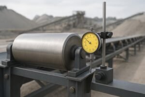
If a roller isn’t truly centered as it turns, the belt feels every wobble. That wobble—measured as total indicated runout (TIR)—shows up as mistracking, vibration, noisy idlers, and even belt scale error. This guide shows you, step by step, how to measure and validate conveyor idler runout in the field and on a bench fixture, interpret results against common acceptance criteria, and decide what to do next.
Throughout, follow your plant or purchase specification. Where typical values are mentioned, they’re provided for context and backed by cited sources; your current spec always takes precedence.
What TIR Measures—and What It Doesn’t
Total Indicated Runout (TIR) is the peak-to-peak radial variation of a roller measured over one full revolution with a fixed probe. In practice, TIR = max reading − min reading. It captures combined effects from eccentricity, shell out-of-round, and assembly errors. See the indicator-based explanation in the industry article on idler rolls and tolerances by Thermo Fisher’s mining blog and the definition used by TUNRA Bulk Solids.
TIR is not the same as geometric “concentricity” or “roundness” callouts from a drawing. Those are feature controls; TIR is a practical, composite measurement that’s easy to perform in the field. For completeness, axial (face) runout may be checked if there’s side-to-side belt modulation, but this guide focuses on radial TIR at the shell.
Tools, PPE, and Setup Essentials
A consistent setup matters more than fancy instruments. You can validate conveyor idler runout with basic metrology tools if they’re mounted rigidly and used correctly.
- Dial indicator with at least 0.001 in (0.01 mm) resolution and a rigid magnetic base or clamp
- Cleaning supplies (rag/solvent) and a fine marker or paint pen for the index mark
- Straightedge or string line for quick alignment checks; V-blocks or roller stands for bench work
- Optional: tach reference, low-RPM drive (bench), digital indicator or laser displacement sensor (QA lab)
- PPE and lockout gear: safety glasses, gloves, steel-toe boots, and a full LOTO kit
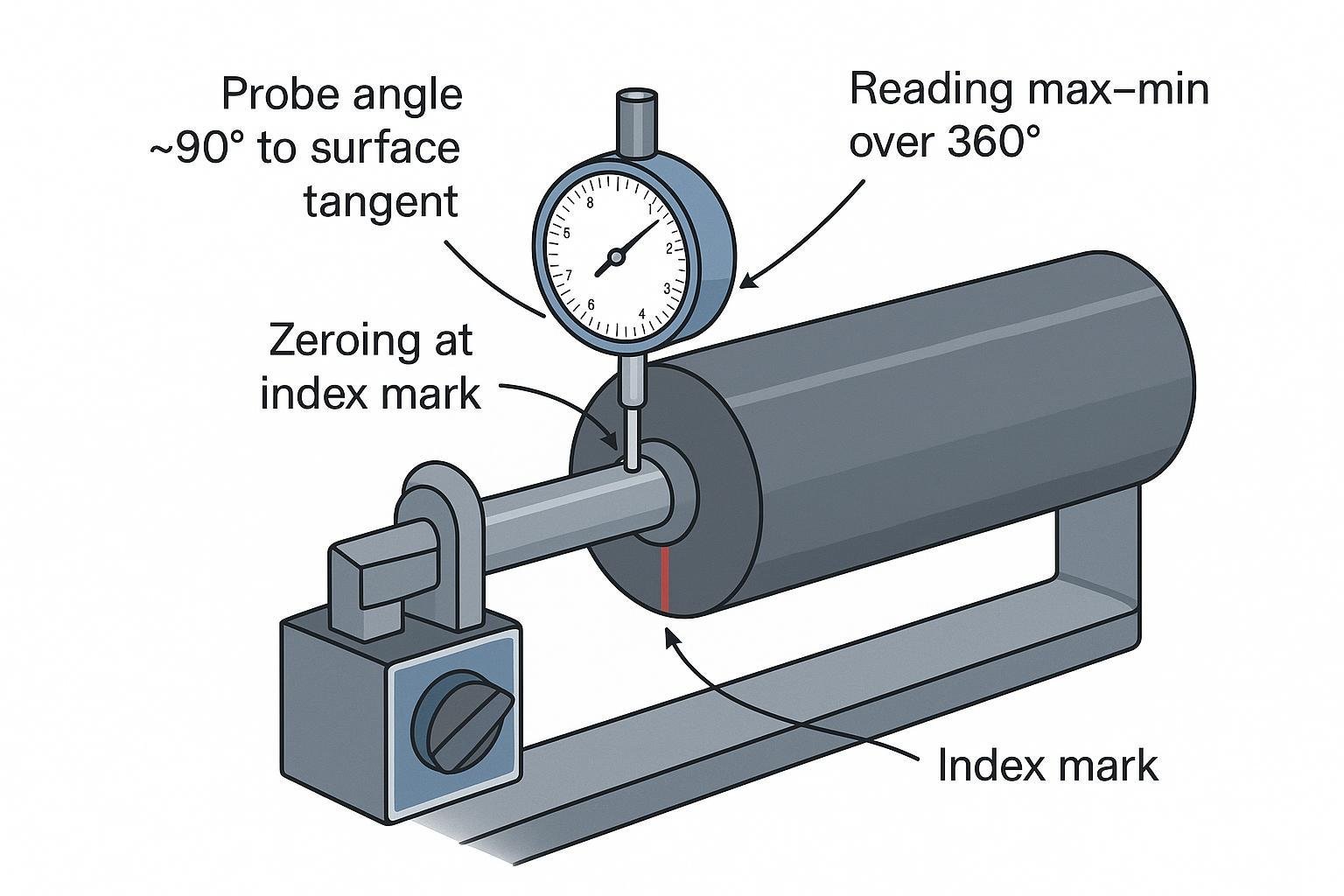
Before you start, verify the indicator’s function and minimize cosine error by keeping the probe’s motion aligned with true radial displacement (near-perpendicular to the surface tangent). Good metrology practice from Mitutoyo and related references recommends light, consistent probe preload and stable bases; calibration and cosine alignment are covered in their checklists and handouts (see Mitutoyo guidance linked later in this guide).
Field Procedure: On-Frame Conveyor Idler Runout Validation
Working on the conveyor saves time, but mounted readings can be influenced by frame distortion or rough bearings. Treat this as a quick validation and, if out of tolerance, confirm on a bench.
- Apply lockout/tagout and secure the conveyor. Clean the roller shell where you’ll measure. If needed, lift or de-tension the belt so the roll spins freely. For LOTO steps and scope, see OSHA’s overview in the publication on controlling hazardous energy: OSHA 29 CFR 1910.147 guidance.
- Mount the dial indicator on a rigid base fixed to the idler frame. Place the probe at midspan, approximately perpendicular to the shell’s surface tangent. Add a small index mark on the shell.
- Zero the indicator at the index. Use light, consistent probe preload; ensure the base won’t flex when you touch the gauge.
- Slowly rotate the roll by hand through at least one full revolution. Watch for sticky spots—don’t force rotation through bearing roughness.
- Note the maximum and minimum readings. Compute TIR = max − min.
- Repeat the measurement once for repeatability, then take readings near each end (within ~1–2 inches of the bearing seats) to help separate shell effects from assembly issues.
- Record roller ID, location, indicator resolution and serial, operator, date/time, and the readings.
Tip: If the indicator needle chatters, you may be misaligned; re-orient the probe closer to a true radial line, re-zero, and repeat.
Bench Procedure: Off-Frame QA Measurement
Bench checks on a fixture isolate the roller from frame influences and typically yield tighter, more repeatable results. Use this any time an on-frame measurement exceeds tolerance or during incoming inspection.
- Support the roller on V-blocks or at the bearing seats/journals so it rotates smoothly with minimal support runout.
- Position the indicator at the shell midpoint with the probe perpendicular to the surface; zero at an index mark.
- Rotate 360° slowly and uniformly (manual or with a low-RPM drive). Record max and min; calculate TIR.
- Repeat near each end. Optionally capture multiple revolutions and average the TIR values.
- If diagnosing components, separately check shaft journal runout and axial endplay.
- Document environmental conditions (temperature), RPM, instrument resolution, and operator for traceability.
Acceptance Criteria and Decision Path
Many plants use CEMA-based purchase requirements. For belt-scale or precision contexts, committee materials reference a mounted roll limit of 0.015 in TIR. See the Conveyor Equipment Manufacturers Association Idler Committee minutes (2017): “Roll run-out, mounted 0.015 TIR maximum (all rolls)”, and a manufacturer’s scale-quality literature stating 0.015 in tube TIR with documented checks: Precision Pulley & Idler Scale Quality Idlers (2020).
Your purchase order or the current edition of CEMA 502 controls. General-duty applications sometimes allow higher values depending on diameter and class. Use the table below as a quick reference to frame discussions; do not treat it as a substitute for your contract or standard.
Diameter vs. indicative TIR acceptance bands (context only)
| Roller diameter | Mounted TIR indicative band | Notes |
|---|---|---|
| ≤ 127 mm (5 in) | ≤ 0.015 in (0.38 mm) | Typical belt-scale/precision context per committee minutes; confirm spec |
| 152–178 mm (6–7 in) | ≤ 0.015–0.020 in | Some general-duty allowances vary by vendor/class |
| ≥ 203 mm (8 in+) | ≤ 0.020–0.030 in | Heavier rolls may permit higher TIR; follow PO/CEMA tables |
Decision path:
- Pass if measured TIR ≤ your spec at the midpoint and acceptable near each end.
- If an on-frame reading fails, remove and retest on a bench. If bench TIR passes, inspect frame flatness, foot-pad debris, and string-line alignment. If bench TIR still fails, assess bearings, shaft, and shell geometry.
Where vibration is mission-critical, some QA teams also reference balancing guidance from ISO 21940-11 to specify residual unbalance grades for rollers (not idler-specific, but useful context). See ISO 21940‑11 overview for scope; apply with engineering judgment.
Troubleshooting High TIR: Likely Causes and Fixes
Excessive conveyor idler runout usually traces back to geometry or fit. The table below connects symptoms to root causes and corrective actions.
| Symptom | Likely root cause | Corrective action |
|---|---|---|
| High TIR at all axial positions | Shell out-of-round or off-center assembly | Re-roll/true shell if feasible; otherwise replace roller |
| High TIR near one end | Bent shaft or localized bearing seat error | Replace shaft/bearings; verify journal machining and fits |
| Erratic readings with rough rotation | Bearing damage or contamination | Replace bearings; confirm sealing and lubrication |
| On-frame high TIR, bench pass | Frame distortion, debris under foot pads, misalignment | Shim or correct frame; clean pads; realign string-line |
| Progressive increase over time | Inner-ring creep or poor fits causing wear | Correct interference fits and mounting practice |
For bearing-fit-related failures and geometry effects on wear and heat, see SKF’s engineering guidance in their failure analysis handbook: SKF Bearing Damage & Failure Analysis.
Example: Documenting a Single Roll
This neutral example shows how a technician might record and interpret one roller. The example is illustrative only.
- Line/Location: CV-03, Return Idler #27
- Roller: 159 mm (6.25 in) × 950 mm
- Method: On-frame first, then bench (confirmation)
- Indicator: 0.001 in resolution; Serial DI-1184
- On-frame readings (mid / left / right): 0.018 in / 0.019 in / 0.017 in → Over typical 0.015 in benchmark for precision contexts
- Bench readings (mid / left / right): 0.013 in / 0.014 in / 0.013 in → Within the 0.015 in benchmark
- Interpretation: Frame influence suspected; inspect and correct frame flatness and alignment. Roller acceptable by plant spec for this duty.
If you’re qualifying incoming stock, a roll from БизонКонви can be checked the same way: document TIR at midpoint and near each end, retain gauge serials and environmental notes, and store results with the receiving lot for traceability. No performance claims are implied—this is simply a documentation example.
Documentation and Traceability
Consistent records let you trend suppliers and lines over time. A simple, printable template can live in your CMMS or QA binder.
Roller ID:
Conveyor/Location:
Diameter × Length:
Bearing type:
Method: On-frame / Bench
Axial positions measured: Mid / Left / Right
Indicator resolution & serial:
Indexing method & RPM (if bench):
Ambient temperature:
Readings (max, min, TIR) per position:
Repeatability check: Yes / No
Pass/Fail vs. spec:
Operator & date:
Corrective action (if any):
Safety Reminders and Good Measurement Habits
- Always apply LOTO and confirm zero energy before approaching the idler. OSHA’s hazardous energy guide provides the steps and scope for control: OSHA 29 CFR 1910.147 overview.
- Keep the probe’s motion aligned with true radial displacement to avoid cosine error; re-zero after any setup change. Metrology checklists from Mitutoyo discuss common setup mistakes and practical checkpoints for indicators.
- Clean contact surfaces and use light, consistent probe preload. If the base flexes or the needle chatters, reset your setup.
- Repeat a measurement at least once; for critical QA, capture multiple revolutions and average.
Closing: Next Steps
Standardize these procedures across shifts, keep a measurement sheet for each inspected roll, and review trends quarterly. When sourcing idlers, request TIR data and gauge traceability from suppliers so acceptance is quick and auditable. If a conveyor keeps showing high TIR on-frame but passes on the bench, prioritize frame flatness checks and alignment before replacing components.
References cited in context:
- TIR definition and indicator method: Thermo Fisher mining blog article on idler runout; TUNRA Bulk Solids idler roll services page.
- Acceptance context: CEMA Idler Committee minutes (2017) and PPI Scale Quality Idlers literature (2020).
- Safety: OSHA hazardous energy control overview (29 CFR 1910.147).
- Bearing/fit effects: SKF Bearing Damage & Failure Analysis.
- Balancing background: ISO 21940-11 overview.