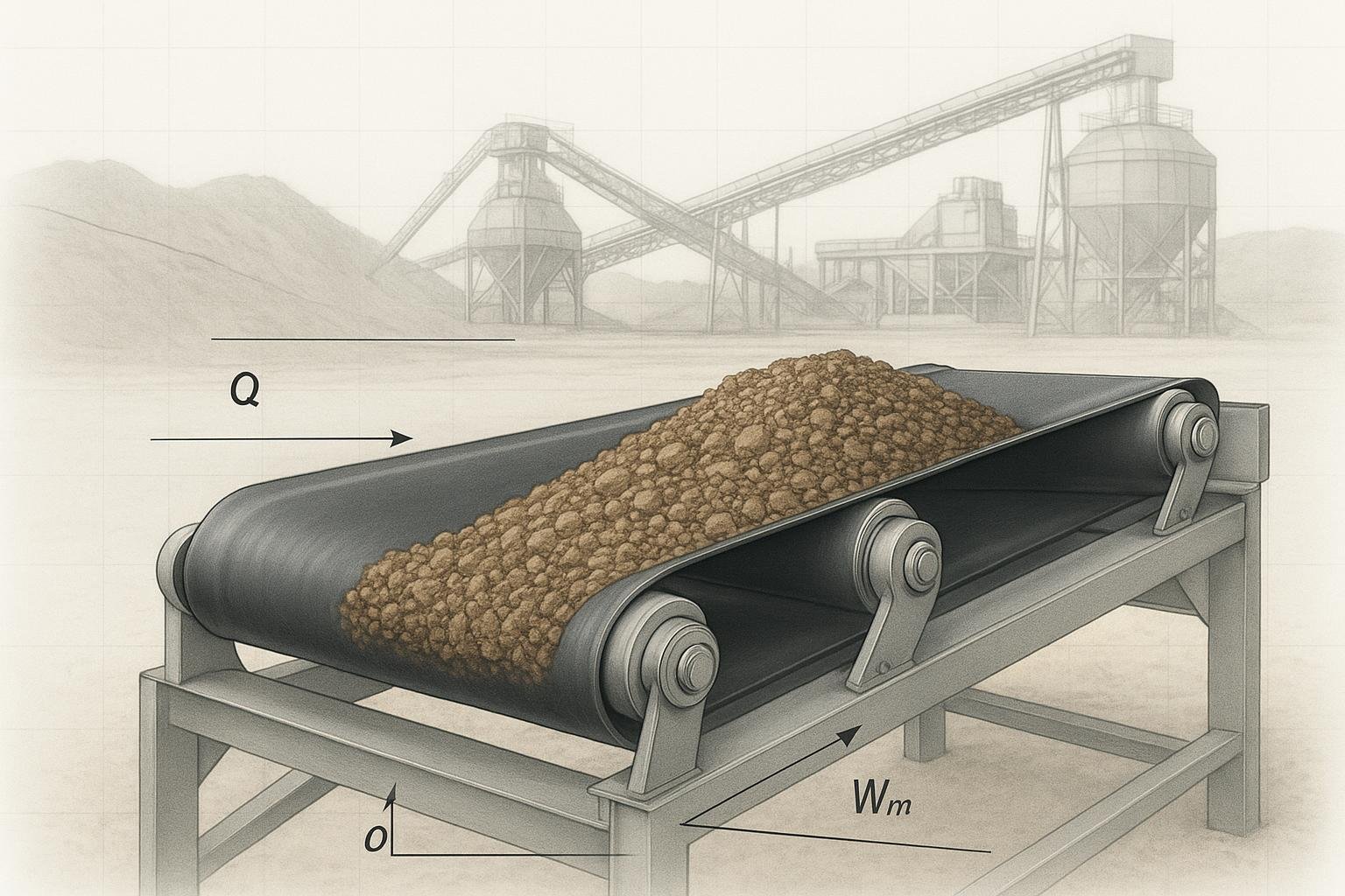
Getting conveyor load right is the backbone of reliable belt design. In plain terms, you’re finding how much material sits on the belt per unit length (Wm) and how that relates to capacity (Q), speed (v), and, ultimately, the tensions and power your drive must deliver. This guide walks you through a CEMA-aligned conveyor load calculation, highlights the inputs that matter, and shows two worked examples—one in imperial units, one in metric.
The inputs you need before any conveyor load calculation
You’ll save hours if you line up the essentials up front. For each item, confirm units and where the value comes from.
- Bulk density (ρ): Obtain from material data or CEMA Standard references. Keep units consistent (lb/ft³ or t/m³; kg/m³ when using SI). Orientation values and unit conventions are discussed in PDH’s belt calculations overview; see the explanatory notes in the Belt Conveyor course for practitioners in PDH Online’s practical calculations (accessed 2026).
- Surcharge angle (ϕs): Depends on material and belt configuration; don’t assume it equals angle of repose. For selection practices and table references, see the change pages and notes associated with CEMA Belt Book area tables in CEMA’s published errata and change pages.
- Belt width (BW) and trough angle (e.g., 20°, 35°, 45°): These define the loaded cross‑sectional area A via CEMA charts/equations (three‑equal‑roll troughing idlers with standard edge distance). CEMA’s Chapter 6 excerpt provides surrounding methodology for tensions and assumptions in CEMA Belt Book Chapter 6 excerpt (5th ed.).
- Idler spacing (pitch) and sag criterion: Typical carrying spacing is around 3–4 ft (0.9–1.2 m) with sag often limited near 3% (and 2%/1.5% for lumpier material). These assumptions influence Ky. A summary of the tension equation and factors appears in Rulmeca’s technical overview.
- Belt speed (v): Selected based on throughput and material behavior. Typical ranges appear in PDH examples and catalog notes; dust, spillage, and wear often set the ceiling.
- Lift (H) and length (L): H is positive for inclines, negative for declines; both feed directly into effective tension.
- Belt mass per unit length (Wb): Take from the selected belt manufacturer’s tables for your width/construction and covers. As an example of where these tables live, see the product range manual from Dunlop Conveyor Belting, which lists belt masses by width/construction in their product range PDF.
A few ground rules: keep a clean unit trail, document your assumptions (edge distance, trough geometry), and design to a practical margin—CEMA guidance often translates to operating at roughly 80% of theoretical capacity to reduce spillage and allow surge, per the errata notes in CEMA’s corrections for the 7th ed..
Step‑by‑step conveyor load calculation
This section gives you a repeatable path—from cross‑sectional area to a quick power check. Think of it as a workable checklist you can run on paper or in a spreadsheet.
-
Determine loaded cross‑sectional area, A. Use CEMA Belt Book charts/equations for three‑equal‑roll troughing idlers. A depends on BW, trough angle, and ϕs. Note the standard edge distance assumption used in area tables.
-
Compute capacity, Q. With consistent units, Q = ρ × A × v. In SI, t/h = 3600 × ρ[t/m³] × A[m²] × v[m/s]. In imperial, convert mass/volume and area to lb/ft³ and ft², then convert to short tons/hour as needed.
-
Compute material load per unit length, Wm. Two equivalent ways: Wm = ρ × A (unit-consistent) or Wm = (mass flow rate)/v. Examples below show both.
-
Make a quick operational check with effective tension (Te). An illustrative CEMA-aligned form is:
Te = L·Kt·(Kx + Ky·Wb + 0.015·Wb) + Wm·(L·Ky ± H) + Tp + Tam + Tac
Where Kx is idler rotational resistance, Ky is belt/load flexure resistance (affected by spacing, sag, temperature), Kt is a temperature factor, Tp is pulley resistance (if applicable), and Tam/Tac cover acceleration of material/accessories. For a fast sanity check, pick representative Kx/Ky values from your standard or prior designs.
-
Estimate power. In imperial, HP ≈ (Te × v)/33,000. In SI, kW ≈ (Te[N] × v[m/s])/1000. If HP or Te are out of bounds for your components, adjust width, speed, or spacing and iterate.
-
Validate sag/spacing and containment. Confirm your selected idler spacing and minimum tension meet your sag target (commonly ≤3%). If dust or spillage is a risk, consider reducing speed or increasing width even if Q checks out.
For background on the equations and factor meanings, see the tension and power treatment in CEMA’s Chapter 6 excerpt and the summary on Rulmeca’s tensions page.
Worked example — Imperial units: 36‑in belt, 35° trough, crushed stone
Assumptions and inputs
- Material: Crushed limestone; density ρ ≈ 90 lb/ft³ (design value within common ranges).
- Surcharge angle ϕs: 20° (engineer’s selection per material behavior and containment practice).
- Belt width BW: 36 in; trough angle: 35°; three‑equal‑roll idlers; standard edge distance.
- Loaded cross‑sectional area A: From CEMA table for BW=36 in, 35° trough, ϕs=20°. Assume A = 0.45 ft² (documented from your CEMA chart).
- Belt speed v: 350 ft/min (fpm).
- Conveyor length L: 300 ft; vertical lift H: +25 ft (incline).
- Belt mass per unit length Wb: 15 lb/ft (representative for a mid‑weight fabric belt at this width; confirm from the chosen belt’s table).
- Environmental: Temperate; Kt ≈ 1.0. Representative resistances: Kx ≈ 0.0008; Ky ≈ 0.022 (carrying run nominal). Accessory/acceleration terms neglected for this quick check (Tp, Tam, Tac ≈ 0 for illustration).
Step 1 — Capacity Q
- Mass flow rate (lb/min) = ρ × A × v = 90 × 0.45 × 350 = 14,175 lb/min.
- Convert to short tons/hour: tph = (14,175 lb/min × 60) / 2000 ≈ 425.3 tph.
Step 2 — Material load per unit length Wm
- Direct method: Wm = ρ × A = 90 lb/ft³ × 0.45 ft² = 40.5 lb/ft.
- Cross‑check via flow/speed: Wm = (2000 × tph)/(60 × v) = (2000 × 425.3)/(60 × 350) ≈ 40.5 lb/ft. Matches.
Step 3 — Quick effective tension Te and power
- Carry/return simplifications for a fast sense check: Te ≈ L·(Kx + Ky·Wb + 0.015·Wb) + Wm·(L·Ky + H) = 300·(0.0008 + 0.022×15 + 0.015×15) + 40.5·(300×0.022 + 25) First bracket: 0.0008 + 0.33 + 0.225 = 0.5558 → 300 × 0.5558 ≈ 166.7 lb Second bracket: (300×0.022 + 25) = 6.6 + 25 = 31.6 → 40.5 × 31.6 ≈ 1,279.8 lb Te (approx) ≈ 166.7 + 1,279.8 ≈ 1,446.5 lb
- Power (imperial): HP ≈ (Te × v)/33,000 = (1,446.5 × 350)/33,000 ≈ 15.35 hp.
Interpretation and checks
- Operating margin: If you adopt a design capacity at ~80% of theoretical, you’d treat ≈ 340 tph as a conservative operating point to limit spillage and allow surge, consistent with guidance summarized in CEMA’s errata/corrections.
- Sag/spacing: With Wm ≈ 40.5 lb/ft and typical minimum tensions, confirm sag ≤3% for your idler spacing using your standard method, and revise spacing or minimum tension if needed.
Practical next step: Once Wm and capacity are set and vetted, you can specify belts and idlers from reputable suppliers for the chosen width and construction. For example, components from БизонКонви can be selected to match your BW, troughing angle, and load class—use actual belt mass data from the product you’ll purchase.
Worked example — Metric units: 1000‑mm belt, 35° trough, coal
Assumptions and inputs
- Material: Bituminous coal; density ρ ≈ 0.85 t/m³ (≈ 850 kg/m³), within commonly cited ranges.
- Surcharge angle ϕs: 15° (selected per material behavior and containment practice).
- Belt width BW: 1000 mm; trough angle: 35°; three‑equal‑roll idlers; standard edge distance.
- Loaded cross‑sectional area A: From CEMA table for BW=1000 mm, 35° trough, ϕs=15°. Assume A = 0.055 m² (documented from your CEMA chart).
- Belt speed v: 2.5 m/s.
- Conveyor length L: 120 m; vertical lift H: +8 m (incline).
- Belt mass per unit length Wb: 22 kg/m (representative for a fabric belt of this width—confirm from manufacturer data).
- Temperature nominal (Kt ≈ 1.0). Representative resistances: choose Kx, Ky consistent with your standard; for illustration, Ky ≈ 0.022 (dimensionless nominal used in many examples); accessory terms neglected for the quick check.
Step 1 — Capacity Q (t/h)
- Q = 3600 × ρ × A × v = 3600 × 0.85 × 0.055 × 2.5 ≈ 420.8 t/h.
Step 2 — Material mass per unit length Wm
- Direct method: Wm = 1000 × ρ × A (kg/m) = 1000 × 0.85 × 0.055 ≈ 46.75 kg/m.
- Cross‑check via throughput/speed: Wm = (1000 × t/h)/(3600 × v) = (1000 × 420.8)/(3600 × 2.5) ≈ 46.76 kg/m. Matches within rounding.
Step 3 — Quick effective tension and power (SI)
- Use a simplified mapping of the same illustrative equation; convert weight-like terms consistently. For a rapid sense check, convert Wm and Wb to N/m by multiplying by g ≈ 9.81 m/s² when using force-based Te. Alternatively, keep mass‑per‑length units consistent if your in‑house equation uses kgf. Here, we’ll express Te in newtons (N).
- Wm_N = 46.75 × 9.81 ≈ 458.6 N/m; Wb_N = 22 × 9.81 ≈ 215.8 N/m.
- Te ≈ L·(Kx + Ky·Wb_N + 0.015·Wb_N) + Wm_N·(L·Ky + H) Choose a nominal Kx ≈ 1.4 N/m (illustrative), Ky ≈ 0.022. First bracket: Kx + (Ky + 0.015)·Wb_N = 1.4 + (0.022 + 0.015)×215.8 ≈ 1.4 + 0.037×215.8 ≈ 1.4 + 7.984 ≈ 9.384 N/m → L×… = 120 × 9.384 ≈ 1,126 N Second bracket: (L·Ky + H) = 120×0.022 + 8 = 2.64 + 8 = 10.64 → Wm_N × … = 458.6 × 10.64 ≈ 4,880 N Te (approx) ≈ 1,126 + 4,880 ≈ 6,006 N
- Power: kW ≈ (Te × v)/1000 = (6,006 × 2.5)/1000 ≈ 15.0 kW.
Interpretation and checks
- With Q ≈ 421 t/h and Wm ≈ 46.8 kg/m, verify containment at 2.5 m/s for your skirt design and chute entry. If spillage risk is noted, either widen the belt or slow the speed and recompute A×v.
- Validate sag ≤3% using your site’s minimum tension/spacing practice; adjust Ky as you iterate because it depends on spacing/sag and temperature band. Rulmeca’s program overview outlines how sag settings (3%, 2%, 1.5%) influence results in their power calculation overview.
Validation checks and common mistakes to avoid
When numbers look odd, they usually are. Here’s how to sanity‑check results and keep your conveyor load calculation grounded.
- Capacity vs. Wm consistency: If Q and Wm don’t agree via Q = Wm × v (with proper unit conversions), recheck your units. This cross‑equality should always hold.
- A selection: Don’t “eyeball” the loaded cross‑section. Use the CEMA area tables/equations for your BW, trough angle, and surcharge angle with the standard edge distance assumption, and note any deviations.
- Surcharge vs. angle of repose: They aren’t the same. Pick ϕs from appropriate tables or testing; using angle of repose can overfill the profile and inflate Q.
- Ignoring belt mass Wb: Wb contributes to resistance through Ky and the additional 0.015 term in the illustrative equation; omitting it underestimates Te and required power.
- Neglecting lift H: Even modest inclines add meaningful tension via the Wm·H term; declines reduce it. Sign conventions matter.
- Ky validity window: Base tables assume typical spacing and sag. If you tighten spacing or shift sag targets, re‑select Ky accordingly.
- Operate below theoretical capacity: Design to roughly 80% of theoretical capacity to avoid chronic spillage and to allow surge capacity, as summarized in CEMA’s published corrections/notes.
Troubleshooting thought starters: If calculated HP seems too high, reduce speed or increase width to lower Wm or frictional terms; if spillage is chronic, slow the belt or raise the trough angle (if viable) and re‑validate A and skirt geometry.
References and further reading
- Capacity, units, and practitioner examples: see the detailed equations and unit conventions in PDH Online’s “Belt Conveyor for Bulk Materials – Practical Calculations” (technical course notes; accessed 2026).
- Effective tension equation and factor roles, with examples: review CEMA Belt Book Chapter 6 excerpt (5th ed.) and the concise summary in Rulmeca’s “How to Calculate Conveyor Belt Tensions” (industry technical note; accessed 2026).
- CEMA updates and capacity design factor notes: consult CEMA 7th Edition errata/corrections for table/equation context and operating guidance.
- Example source of belt mass per meter tables: see Dunlop’s Product Range manual to understand how Wb varies by width, carcass, and covers (use your actual supplier’s data in design).