
Getting impact beds right isn’t just about swapping in a new cradle under the chute. Proper geometry, clearances, and commissioning determine whether your loading zone runs clean and cool—or cooks UHMW caps, chews up belt edges, and sheds spillage. This guide distills proven field practices for impact bed installation, with numeric tolerances, safety essentials, and a maintenance playbook validated against OEM instructions and standards.
Who it’s for: maintenance and reliability engineers, conveyor technicians, site supervisors, and project managers tasked with safe, repeatable installs in mining, ports, cement, steel, power, and other bulk-handling operations.
Quick-reference geometry and tolerances for impact bed installation
Correct geometry stabilizes the belt profile, protects splices, and enables tight skirting without drag. The figures below align with OEM guidance; always verify your specific model’s instructions.
| Артикул | Recommended practice (verify per model) | Source |
|---|---|---|
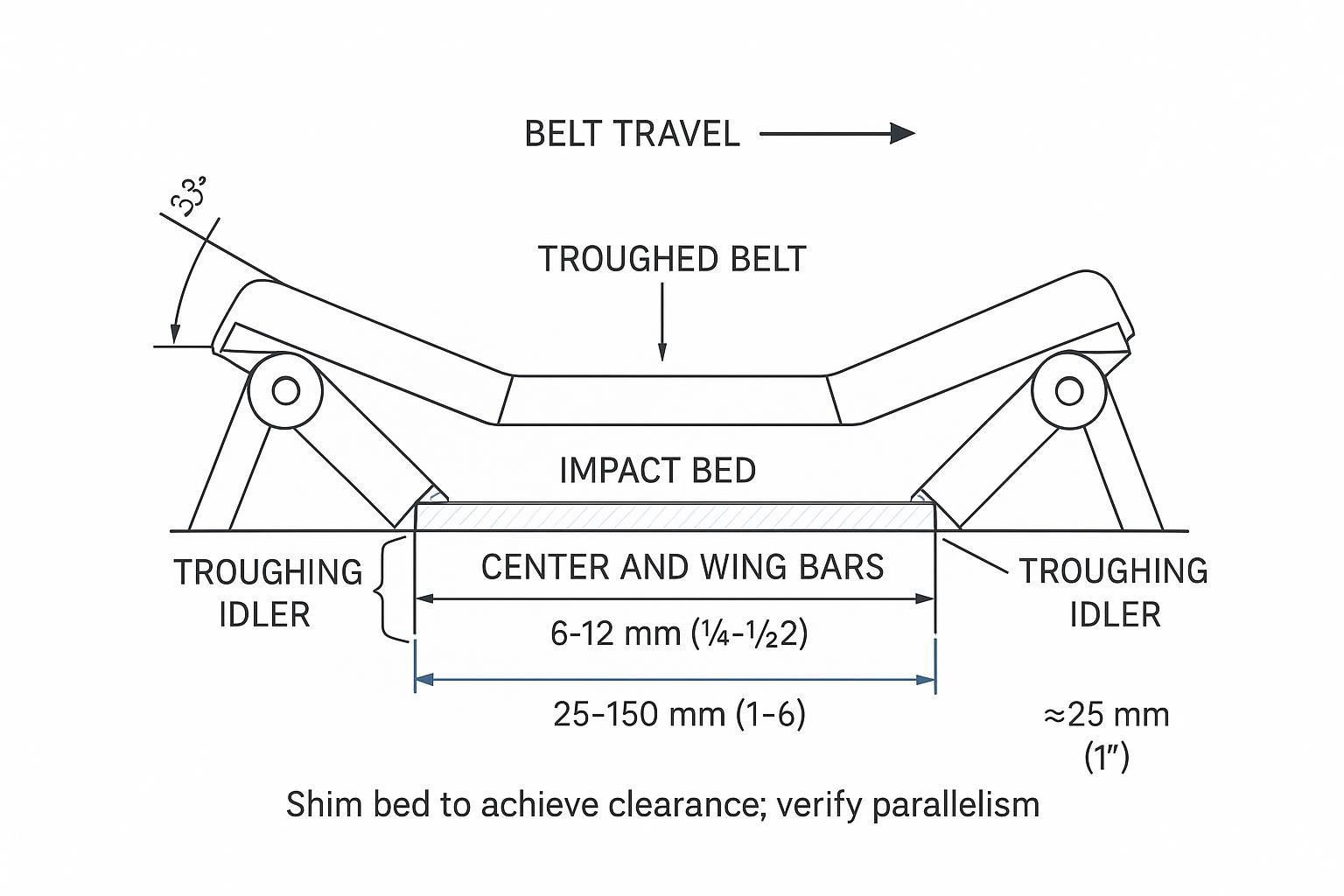
| Belt-to-bar clearance (troughed) | Keep the slider/impact bars below the adjacent idler line. Flexco: set the bed about 1/4–1/2 in (6–12 mm) below the leading and trailing center idlers. Martin: keep ≤1/2 in (13 mm) from bar top to belt bottom; some HD variants set ~3/4 in (19 mm) below unloaded belt line. | Flexco Modular Impact Bed IOM (2019–2021); Martin Impact Cradle IOMs |
| Idlers before/after the bed | Install matching troughing idlers immediately before and after the bed—commonly 1–6 in (25–150 mm) from the bed, with ~1 in (25 mm) between bar ends and idler faces. | Flexco Modular Impact Bed IOM; Martin Impact Cradle IOMs |
| Trough angle match | Set wing bars to the target trough angle (e.g., 20°, 35°, 45°) and ensure approach/exit idlers match angle and height for a smooth path. | OEM IOMs; CEMA practice |
According to the Flexco Modular Impact Bed instructions (2019–2021), the bed should be shimmed to sit 1/4–1/2 in below adjacent idlers, with idlers positioned closely before and after the bed for a consistent belt path, and hardware torqued per the IOM. See the Flexco guidance in the Modular Impact Bed IOM (X3997). Martin Engineering echoes similar geometry and spacing in its cradle manuals—e.g., maintaining a maximum 1/2 in clearance from bar top to the belt bottom on troughed systems; see Martin’s Impact Cradle IOMs and the HD Impact Cradle manual. Douglas provides matching placement and anchoring notes in its Floating Impact Bed Safety, Operation & Maintenance Manual (SOMM).
12-step impact bed installation workflow
- Lockout/tagout and job planning. Apply energy control per OSHA (1910.147); verify zero energy and establish a test-run plan if brief energization is required for alignment checks. Where full lockout is impracticable during specific adjustments, document a risk assessment consistent with ANSI/ASSP Z244.1 alternative methods (2024) while still meeting OSHA obligations.
- Access, rigging, and tools. Confirm safe access and lifting points. Typical tools include 3/4 in sockets/impact, torque wrench, shims, square, straightedge, and a drill with ~13/16 in bit for templating base holes where permitted by the structure.
- Mark and square. Mark conveyor centerlines on both stringers at the loading zone. Square cross-members perpendicular to belt travel to prevent frame twist during torquing.
- Prep the structure. Clean stringers, remove burrs, and check for flatness. Repair distorted steel. Confirm clearance for skirting hardware and chute liners.
- Position cross-members/bases. Place or rig the bed frame/cross-members. Bolt or stitch-weld per OEM drawings. Snug fasteners; confirm perpendicularity and level.
- Set trough geometry. Adjust wing supports to the specified trough angle (20°, 35°, or 45°). Verify the approach and exit idlers are the same make, angle, and height class used in the load zone.
- Install bars in sequence. Fit center bars first, then wings. Orient tapered ends with belt travel as shown in OEM diagrams. Maintain ~1 in (25 mm) from bar ends to adjacent idler faces.
- Shim to clearance. Shim the bed to achieve proper belt-to-bar clearance: Flexco guidance sets the bed 1/4–1/2 in (6–12 mm) below adjacent idlers; Martin guidance caps clearance at ≤1/2 in (13 mm) to the belt bottom on troughed belts, with some HD models set ~3/4 in (19 mm) below unloaded belt line.
- Place idlers before/after. Install matching troughing idlers immediately before and after the bed—commonly 1–6 in (25–150 mm) from the frame—so the belt transitions smoothly onto and off of the bed.
- Fit skirting and sealing. With the belt stabilized over the bed, set skirt liners to barely contact the belt. Keep a consistent free edge and avoid riding the UHMW surface.
- Torque and verify alignment. Torque hardware to the model’s specification (e.g., many Flexco assemblies list ~60 ft‑lb for certain bar/frame fasteners—verify in your IOM). Recheck parallelism to belt travel and confirm no bar is proud of the set line.
- Commissioning run and documentation. Clear the area, remove tools, and conduct a brief test run. Listen for rubbing, feel for heat at bars, and watch the skirt seal. Re-lock, re‑shim if needed, and record shim heights/torques with photos for future PMs.
For detailed manufacturer instructions and drawings, consult the Flexco Modular Impact Bed IOM (2021), Martin LD/MD Impact Cradle IOM, and Douglas Floating Impact Bed SOMM.
Anchoring and alignment best practices
The goal is rigid, square support that still preserves the designed shock absorption.
- Anchoring method. Bolting is preferred where the structure allows through-bolts and access for torque checks. Welding is acceptable per OEM drawings when the base includes weld pads and the structure is suitably thick—use qualified procedures and a fire watch. Some models use floating or slide-in mounts; keep those guides clean and aligned to prevent binding.
- Fasteners and torque. Use the grade and size specified in your kit. Where OEMs publish values (e.g., certain Flexco beds list ~60 ft‑lb for specific hardware), follow them; otherwise reference the IOM. Re‑torque after the commissioning run.
- Idlers before/after the bed. Maintain very short gaps between bed and adjacent idlers (often 1–6 in / 25–150 mm), with ~1 in (25 mm) from bar ends to idler faces, to avoid a “kinked” belt path.
- Shimming strategy. Shim evenly under cross-members to achieve clearance. Avoid stacking thin shims in tall piles; use solid spacers where needed. Record final shim thicknesses.
Refer to OEM geometry: Flexco and Martin both call for small no-load clearance under the belt, with tight idler placement bracketing the bed. See Flexco’s Modular Impact Bed IOM (2019–2021) и Martin’s HD Impact Cradle manual. Douglas provides anchoring illustrations and hole sizing in the Floating Impact Bed SOMM.
Inspection and maintenance schedule
A fixed interval isn’t universal—drop height, lump size, belt speed, and environment drive wear. Use these baseline practices and refine with your data and OEM thresholds.
- Weekly visual: Remove buildup; check for continuous rubbing or hot spots; verify skirt contact and free belt edge; look for loose fasteners and frame distortion; confirm idler approach/exit integrity.
- Monthly hands-on: Measure UHMW cap wear at several points; plan replacement once roughly 50–70% of cap thickness is consumed (or if glazing/cracking appears). Re‑shim to maintain clearance; re‑torque hardware to spec; test run and re‑inspect.
- Quarterly/annual audit: Validate trough angle, bar heights, idler types/spacing, chute liner condition, and skirt adjustment. Update SOPs with photos and measurements.
Flexco recommends routine checks and hardware verification in its slider and modular bed instructions; see the Flexco Slider/Impact Bed IOM (2021). Martin’s cradle manuals provide comparable inspection items; see the LD/MD Impact Cradle IOM.
Troubleshooting and common mistakes
- Bed set flush or above idlers. Symptom: heat, UHMW glazing, persistent noise. Fix: re‑shim to 1/4–1/2 in below adjacent idlers (or OEM-stated gap) and re-test.
- Mismatched approach/exit idlers. Symptom: spillage at bed edges, belt ripple. Fix: install identical idlers (angle/height/class) immediately before/after the bed; confirm ~1 in gap from bar ends to idler faces.
- Loading in the transition. Symptom: belt cupping, splice distress, material splash. Fix: relocate loading after the first fully troughed idler per CEMA practice and belt OEM guidance.
- Skirt interference. Symptom: UHMW wear steps at the outer bars, heat at skirt contact. Fix: reset skirts to barely contact a stabilized belt; maintain a consistent free edge.
- Over‑torqued, twisted frame. Symptom: uneven support, rubbing on one side. Fix: loosen, square, re‑shim, and torque in a star pattern to OEM values.
For geometry and spacing tolerances, reference the Flexco Modular Impact Bed IOM и Martin’s cradle manuals.
Safety and standards you can’t skip
- Lockout/tagout. OSHA’s standard requires written procedures, device-specific isolation, verification of zero energy, training, and periodic audits. See OSHA’s Control of Hazardous Energy program.
- Alternative methods. When full lockout is demonstrably impracticable for a brief test/run, ANSI/ASSP Z244.1 (2024) lays out risk-assessed alternatives—preparation, isolation, verification, group LOTO, and supervised testing. See ANSI/ASSP Z244.1 overview. Note that OSHA has not “adopted” alternatives; employers remain accountable under 1910.147.
- Rigging. Use rated lift points and gear; control pinch points; maintain exclusion zones; and appoint a signal person when visibility is limited. Document every lift.
Neutral vendor example: matching belts, idlers, and beds with BisonConvey
Here’s the deal: the easiest installs happen when belt, idler, and bed specs are aligned from the start. Suppose a site is selecting a new loading-zone package for a 1200 mm EP/NN belt running 4.5 m/s, with 200 mm max lump size and a 2.5 m drop. The planner chooses troughing idlers at 35° with CEMA C–D class rolls in the load zone.
- Belt and idlers as the baseline. From a belt supplier’s spec (e.g., tensile rating and recommended transition distances) and the idler family (angle and roll diameter), you set the target belt line and trough geometry. A vendor such as БизонКонви provides compatible EP/NN belt classes and troughing idlers that define the approach/exit height and stiffness envelope.
- Selecting the bed class and bar geometry. With expected impact energy (lump mass × drop height) and belt speed known, choose an impact bed rated for the zone’s energy class and speed range (per the bed OEM’s catalog). A medium-to-heavy-duty bed with UHMW-capped bars and generous wing support typically matches a 35° load zone.
- Translating to installation settings. Using the idler datum, shim the bed to sit about 1/4–1/2 in below adjacent center idlers (Flexco guidance) or maintain ≤1/2 in to the belt bottom (Martin guidance), and place matching troughing idlers 1–6 in before and after the bed. Set skirting to barely contact the stabilized belt. Document bar wear points and re‑torque checks in the site’s PM schedule.
This example isn’t an endorsement of any specific model. It shows how using a belt/idler package and the bed OEM’s IOM together yields predictable clearances and a cleaner seal at the loading point.
References and further reading
- Flexco. See the 2021 revision of the Modular Impact Bed IOM (X3997) and the Slider/Impact Bed IOM (X2634) for geometry, hardware, and inspection notes.
- Martin Engineering. The LD/MD Impact Cradle IOM and the HD Impact Cradle manual provide clearance limits, placement, and installation drawings.
- Douglas Manufacturing. The Floating Impact Bed SOMM includes anchoring, templating, and safety/operation guidance.
- OSHA. Control of Hazardous Energy (1910.147) resources detail LOTO requirements and testing sequences.
- ANSI/ASSP. Z244.1 (2024) overview on alternative methods outlines risk-based approaches for tasks where full lockout is impracticable.
Always confirm model-specific tolerances, torque values, and bar materials in your manufacturer’s latest IOM. When in doubt, measure, shim, test, and document—then keep the geometry stable with a disciplined PM cadence.