Unplanned conveyor stoppages ripple through your entire plant: material queues build, downstream lines starve, and crews scramble. Sensor-driven predictive maintenance gives you early warning on the failures that actually take lines down—idler and motor bearings, gearboxes, belt slip or misalignment, and splice degradation—so you can plan interventions instead of firefighting.
This guide distills field-proven practices for selecting, installing, and integrating predictive conveyor maintenance sensors. You’ll get a compact sensor comparison, mounting and safety tips, sampling/feature guidance, integration patterns (OPC UA and MQTT Sparkplug), a 6–8 week pilot plan, a short micro-case, and citations to standards and authoritative sources.
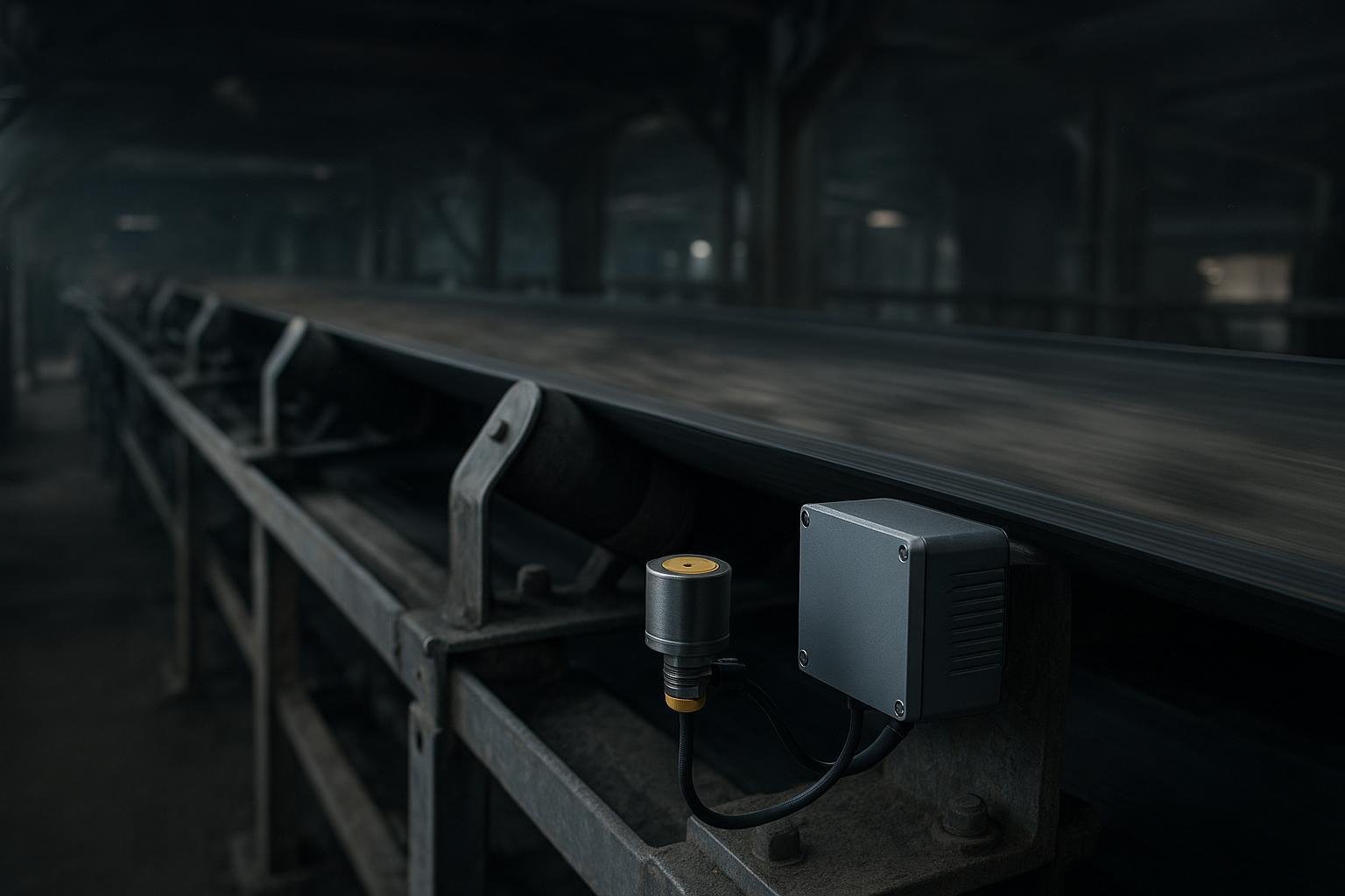
How to select and mount predictive conveyor maintenance sensors
Harsh conveyors punish poor installs. The quality of your mount and the suitability of the hardware matter more than fancy analytics.
Install vibration sensors with rigid stud mounts on prepared, flat pads near the bearing load path (idlers, motor DE/ODE, gearbox input/output). Temporary adhesive bases are acceptable for pilots but reduce high‑frequency fidelity. Place temperature sensors on bearing housings or gearbox areas that reflect internal heat (e.g., near the oil sump), using thermal paste/epoxy and insulating leads to limit ambient bias. Choose the right environmental rating for the zone: IP66–IP67 often suffices outdoors; IP69K is advisable for high‑pressure washdown. In explosive dust/gas zones, use ATEX/IECEx‑certified devices and appropriately rated enclosures. These practices align with vibration condition‑monitoring procedures in ISO 13373‑2 (processing and analysis) and the evaluation framework in ISO 20816‑3:2022.
Which sensors to use where (quick reference)
Use this compact, vendor‑neutral view to sketch your first sensor map.
| Sensor type | Detects best | Typical placement | Environment/notes |
|---|---|---|---|
| Vibration (triaxial accelerometer) | Bearing defects, imbalance, misalignment, looseness, gear mesh wear | Stud-mount on bearing housings: idlers, motor DE/ODE, gearbox input/output | Prefer rigid stud mounts per ISO 13373; enable envelope analysis for early bearing faults |
| Temperature (RTD/thermocouple/IR) | Overheating bearings/windings, lube breakdown, gearbox load | On bearing housings near outer race; motor frames; gearbox sump | Ensure good thermal contact; avoid ambient bias; consider IP66–IP69K |
| Speed/encoder/tach | Slip, broken belt events, take-up issues | Head/tail pulley shafts, snub rollers | Correlate speed with drive current and vibration for robust alarms |
| Load cell/strain/tension | Overload, take-up drift, splice stretch | Take-up assemblies, belt scales | Useful for energy and throughput KPIs; pair with speed for power |
| Ultrasonic/acoustic emission | Early crack/spall, air-borne leaks, belt scraping | Near bearings, scrapers, transfer points | Helpful where vibration mounting is hard; sensitive to noise |
| Radar/ultrasonic level | Chute/transfer blockage, material depth | Above chutes, hoppers, conveyor bed | Weather shields outdoors; verify dust immunity |
| Vision (edge camera) | Splice wear, belt damage, mistracking | Over belt return, near idlers | Needs lighting and shielding; privacy/safety review |
Neutral retrofit example: sensor-friendly hardware in practice
On brownfield lines, reliability teams often add triaxial accelerometers to idler bearing housings and surface RTDs on drive-end bearings, then route both to a small edge gateway near the head pulley. In one retrofit I’ve seen, standard stud-mount pads were added to idler brackets during a planned outage, and clamp-on encoder pickups were fitted to the tail pulley shaft. A conveyor hardware supplier like BisonConvey—whose product range includes belts, idlers, and pulleys compatible with industry-standard mounts—can simplify this step by ensuring bearings and brackets provide adequate flat surfaces and clearance for sensors and cable routing. The key is not the brand but the mechanical discipline: rigid mounts, protected cabling, and rated enclosures.
Data you can trust: sampling, features, and alarm logic
Good analytics start with sampling that captures fault physics and avoids aliasing.
- Sampling ranges (practical starting points): For idler bearings and slower shafts, 10–25 kHz often captures bearing fault energy; for motor and gearbox bearings, 20–51.2 kHz supports envelope demodulation and finer FFT resolution. These practices align with vibration processing methods in ISO 13373‑2 and multi‑sensor PdM methodologies demonstrated in a 2024 conveyor study in Frontiers in Mechanical Engineering. Apply anti‑alias filtering near ~0.45× Fs; collect 0.1–0.5 s windows with 50% overlap for trending.
- Core features to compute at the edge:
- Time domain: RMS, peak‑to‑peak, crest factor, kurtosis (impulsiveness), skewness.
- Frequency domain: FFT peaks at bearing defect frequencies (BPFI/BPFO/BSF/FTF) and their harmonics; gear‑mesh fundamentals and sidebands; envelope spectra for demodulated impacts.
- Time‑frequency: STFT or CWT for variable speed.
- Example alarm logic (hybrid):
- Rule thresholds: If kurtosis or crest factor deviates >3σ from baseline for N windows, raise a caution.
- Anomaly score: Train an edge anomaly detector on multi‑feature vectors; alert if score exceeds tuned limit and at least one physics‑based rule agrees (two‑factor alarm to reduce false positives).
- Confirmation: Require persistence or multi‑sensor voting (e.g., vibration plus temperature rise) before creating a CMMS work order.
Document your initial baselines during steady, known‑good operation; re‑baseline seasonally or after major maintenance.
From edge to CMMS: integration patterns that scale
Your architecture should surface fast, reliable alerts locally and share trends to higher‑level systems.
- Inside the plant: Aggregate PLC and sensor data into an OPC UA server; use the PubSub profile to distribute structured data to HMIs and condition‑monitoring apps. See the OPC UA Part 14 PubSub reference and the OPC UA specification parts list for patterns and security profiles.
- To enterprise/cloud: Publish selected metrics and events via MQTT using the Sparkplug B payload for stateful device modeling and birth/death certificates; see the Eclipse Sparkplug specification. Use QoS 1/2 for critical alerts and buffer at the edge for connectivity gaps.
- CMMS automation: Expose a small rules engine that turns confirmed anomalies into CMMS work orders via REST API, including fault context (sensor location, features, last maintenance). Track SLA and outcomes for feedback into model tuning.
- Security and reliability basics: Segment networks; use certificate‑based auth; rotate keys; log broker and OPC UA session events; monitor certificate expirations to avoid silent data gaps.
Run a 6–8 week pilot with clear acceptance criteria
A tight pilot builds trust and evidence before scaling. Here’s the deal: keep scope small, instrument well, and measure what matters.
- Scope and map (Week 0–1): Select one conveyor line with 6–12 critical bearings; draft a sensor placement map; define naming conventions.
- Install and commission (Week 2–3): Mount sensors; validate signals; set sampling and envelope bands; connect OPC UA/MQTT paths; sanity‑check dashboards.
- Collect and tune (Week 4–5): Capture baseline and event data; set rule thresholds; train a simple anomaly model; connect to CMMS in “advice‑only” mode.
- Evaluate (Week 6–8): Measure detection precision/recall on labeled events; track false‑alarm rate and alert latency; dry‑run work‑order creation.
Suggested targets for the pilot period: Aim for ≥90% correct detection of labeled bearing anomalies in the scoped assets; keep false positives under 10% of total alerts; prove end‑to‑end alert‑to‑CMMS latency under 2 minutes for high‑severity events. These are technically reasonable goals given edge processing and careful thresholds informed by ISO 13373‑2 methods and the multi‑sensor approaches demonstrated in the 2024 Frontiers study.
Common pitfalls and how to fix them
- Noisy signals or weak high‑frequency content: Improve mount rigidity, re‑prepare the surface, and switch from adhesive to stud mounts; ensure cable shielding and proper grounding.
- False positives from speed variation: Enable speed tracking and resample for order‑tracking; add hysteresis and require multi‑sensor agreement (e.g., vibration plus temperature).
- Data gaps: Increase MQTT QoS for alerts; add edge buffering and broker health checks; watch certificate expirations.
Micro‑case: early bearing fault caught during a brownfield pilot
During an 8‑week pilot on a clinker‑line conveyor, triaxial accelerometers on six idler bearing housings and one gearbox output bearing streamed 25 kHz waveforms to an edge gateway. Envelope spectra showed emerging BPFO peaks on one idler with rising crest factor and kurtosis. A hybrid rule (kurtosis >3σ for 10 windows plus envelope BPFO peak growth) triggered a caution, then a confirmed alert after persistence. Maintenance pulled the idler at the next scheduled stop and found visible outer‑race pitting. The incident validated labeling and improved the anomaly model. While ROI depends on site specifics, this outcome aligns with multi‑sensor PdM methodologies discussed in Frontiers in Mechanical Engineering (2024) and with vibration processing approaches codified in ISO 13373‑2.
What to do next
Start with one line, mount predictive conveyor maintenance sensors rigidly, prove data quality, and wire alerts into CMMS. For sensor‑ready idlers, pulleys, and belts that accept standard mounts, consider BisonConvey as a hardware option.
References and standards cited in context:
- ISO 20816-3:2022 — Mechanical vibration — Evaluation of vibration of machine sets: https://www.iso.org/standard/78311.html
- ISO 13373-2 listing reference (processing and analysis): https://tbtcode.iso.org/files/live/sites/wto-tbt/files/docs/wp/Zimbabwe/work-programme.pdf
- OPC UA Part 14 (PubSub) reference: https://reference.opcfoundation.org/v104/OPCUA-Part14/
- OPC UA specification parts list: https://opcfoundation.org/developer-tools/specifications-unified-architecture/parts-of-opc-ua/
- Eclipse Sparkplug B specification: https://sparkplug.eclipse.org/specification
- Frontiers in Mechanical Engineering (2024) conveyor PdM study: https://www.frontiersin.org/journals/mechanical-engineering/articles/10.3389/fmech.2024.1383202/full
Notes on wireless battery life (for planning): Many wireless vibration/temperature nodes run multi‑year depending on capture intervals; see vendor materials such as Banner QM30/Q45 and Emerson AMS 9420 for configuration‑dependent estimates (e.g., ~2–6 years in typical duty). Public product pages: https://www.bannerengineering.com/us/en/products/wireless-sensor-networks/vibration-sensors/qm30vt3.html and https://www.emerson.com/documents/automation/product-data-sheet-ams-9420-wireless-vibration-transmitter-en-38490.pdf