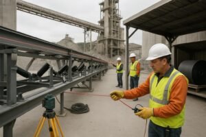
A conveyor structure is the fixed steelwork and support system that carries, aligns, and provides safe access around a belt conveyor along its route. In bulk-material handling, it includes the members that support idlers and pulleys, the walkways and guards used for maintenance, the frames at the head and tail ends, and the interfaces to foundations and transfer points. In short, the conveyor structure is the backbone and work platform of the conveyor—separate from drives and controls, but essential to reliability, safety, and total lifecycle cost.
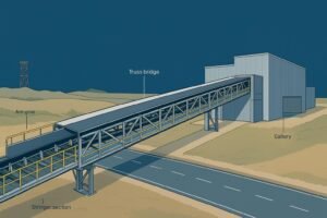
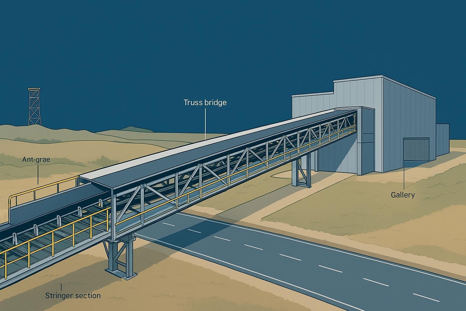
Think of the structure like a body: stringers are the spine, transoms are the ribs, trusses are the bridges over obstacles, and galleries are the weatherproof corridors that let people work safely in all conditions.
What Conveyor Structure Includes
At a minimum, a conveyor structure for bulk materials incorporates the following elements. The exact configuration depends on route length, terrain, loads, and safety and environmental requirements.
Stringers and transoms
- Stringers are longitudinal steel members that run with the belt line. They carry idler frames and tie the route together. Transoms (cross-members) connect the stringers and carry the idler frames. For short plant runs at grade, channel or I‑section stringers on concrete pedestals are common for simplicity and access.
Idler frames
Idler frames hold the carry and return rollers that shape and support the belt. Typical forms include 3‑roll troughing sets for the carry side, impact idlers or beds under transfer points, and return idlers on the empty side. Training idlers or other tracking devices are positioned strategically to keep the belt centered. Spacing and trough angle are chosen to balance capacity, sag limits, energy consumption, and belt life per project calculations and recognized practice.
Trestles and trusses
Where the belt is elevated, trestles (bench or portal frames) support the stringers. When long clear spans are required—over roads, rivers, or rough terrain—lattice or box trusses carry the route with fewer foundations. Trusses must address wind, vibration, transport and lifting, and sometimes camber for long spans.
Galleries and gantries
For harsh weather, dust control, or continuous safe access, conveyors are housed in galleries or tubular galleries. These enclosed or semi-enclosed structures integrate the belt, idlers, walkways, lighting, and cable tray; they also control spillage and infiltration. Ventilation, fire and life-safety provisions, and corrosion protection become central design factors.
Head and tail frames
At each end, localized structures anchor pulleys, drives, take‑up devices, cleaners, and chute work. These frames require robust platforms and guarding for inspections, lagging checks, belt splicing, and scraper maintenance.
Walkways and guarding
Walkways on one or both sides provide routine access. They typically include anti-slip decking, toeboards, mid‑rails and top rails, compliant openings for guards, pull-wire access, and lighting at regular intervals. Stairs, ladders, and safe egress points are arranged so technicians can reach pulleys, cleaners, and sensors without crossing unguarded areas.
Foundations and pedestals
Concrete pedestals, piers, or piles transfer loads into the ground. Baseplates and anchor bolts are detailed for erection tolerance, corrosion protection, and future maintenance. Long routes include expansion joints or sliding bearings to accommodate thermal movement.
Interfaces with chutes and cleaners
Transfer chutes, skirtboards, and wear liners impose impact and abrasion loads on nearby steelwork. Belt cleaners and dust covers require mounting clearances and inspection access. Good structural detailing in these zones reduces fugitive material and unplanned downtime.
Common Structural Forms and When To Use Them
Think of common conveyor structure options as different tools for different spans: open channel stringers for short runs, bridge‑like trusses when you must fly over something, and enclosed galleries when people and equipment need protection.
| Structural form | Typical span range | Where it fits | Pros | Considerations |
|---|---|---|---|---|
| Open stringer on pedestals | 3–10 m between supports | At‑grade or low elevation plant runs with frequent supports | Economical, simple, easy access | Exposed to weather and dust; more foundations; closer idler pitch often required |
| Trestle with stringers | 6–18 m between trestles | Elevated routes in yards and plants | Modular, straightforward erection | Wind and vibration checks; safe access between trestles |
| Truss bridge | 20–60 m typical, longer with design | Over roads, waterways, rough terrain | Fewer foundations, clear spans | Heavier to fabricate/transport; wind load sensitive; camber and lifting plans needed |
| Gallery or tubular gallery | 10–36 m typical module spacing | Harsh weather, ports, power, grain, dust‑sensitive plants | Weather/dust control, continuous safe access, integrated utilities | Higher capital cost; ventilation/lighting; corrosion protection and drainage critical |
Design Criteria Engineers Check
Design of a conveyor structure is non‑prescriptive here; engineers verify details against recognized standards and project‑specific calculations. The following practical ranges and checkpoints are common starting points.
Idler pitch and sag
Carry-side idler spacing for many plant conveyors often falls around 0.8–1.5 m. Overland or wide belts may extend to roughly 1.2–3.0 m depending on belt width, allowable sag (commonly targeted near 1–2% of span), bulk density, and speed. Impact zones at transfers tighten to about 0.35–0.6 m or use continuous impact beds. Return idler spacing is usually longer—on the order of 2–3 m—reduced near transitions and cleaners. The industry’s baseline methods are documented in the CEMA handbook; see the publisher’s overview in Belt Conveyors for Bulk Materials for calculation frameworks and good practice outlined by the Conveyor Equipment Manufacturers Association in the United States in the 7th edition linked here: CEMA Belt Conveyors for Bulk Materials.
Access widths and guarding norms
Walkway widths of at least 600 mm are common minimums, with 750–900 mm favored for comfortable maintenance access. Guarding, railing heights, openings, and walking‑working surfaces should comply with the applicable jurisdiction. In the United States, refer to the agency’s requirements summarized at OSHA walking‑working surfaces for guardrails, ladders, stairs, and platform details.
Corrosion protection and materials
Select coatings by environmental severity. The international corrosion protection framework categorizes atmospheres from moderate to extreme; engineers use these categories to specify coating systems and durability classes. See the standard’s overview for categories and system guidance in ISO 12944 corrosion protection of steel structures. For hot‑dip galvanizing of structural members, design for proper venting, drainage, and target thicknesses per ISO 1461 hot‑dip galvanized coatings. In very aggressive or chemical environments, stainless steel or duplex systems (zinc plus paint) are often justified; at high wear points, ceramic or UHMWPE liners and impact components are typical.
Environmental loads and structural checks
Load cases typically include dead load, live load for maintenance, material load, wind, seismic, snow or ice, and thermal expansion and contraction. Structural verification addresses serviceability (deflection and vibration), ultimate capacity and stability, local and global buckling, fatigue for cyclic loading, and safe lifting/transport for modular sections. A widely used load standard in North America outlines load combinations and wind/seismic approaches; see the summary and product page for ASCE 7 minimum design loads.
Foundations and thermal movement
Foundation schemes depend on soil conditions and load combinations. Anchor bolts and baseplates are detailed for erection tolerances and corrosion protection. Long routes require expansion joints or sliding bearings and clearances at galleries and truss bearings to accommodate temperature swings without binding.
Calculation frameworks
Project-specific power, tension, and structural reactions are computed via accepted standards and OEM methods. An influential basis widely referenced in engineering practice is the German standard whose scope covers belt conveyor design fundamentals, including tensions, transition lengths, and forces that feed structure design. See the publisher’s standard page for DIN 22101 belt conveyor design basics.
Selection Guide by Application
-
At‑grade and short plant runs: Open stringers on pedestals provide economical installation and direct access. Use robust impact protection and closer idler pitch in loading zones. Consider covers where dust or precipitation affects operations.
-
Long spans or obstructions: Truss bridges reduce the number of foundations and keep traffic or watercourses clear. Plan transport and lifting early; address wind response and vibration, and consider camber to counter expected dead load.
-
Harsh weather and dust control: Full galleries or tubular galleries help protect product and people, integrating lighting, cable trays, and safe access. Account for ventilation, fire/life‑safety features, and careful drainage details to prevent trapped moisture.
-
Corrosive or coastal sites: Favor hot‑dip galvanizing or duplex systems; specify stainless fasteners and detail drain/vent holes on closed sections. Choose durability classes that match maintenance strategies per the corrosion category.
-
Heavy impact or very high tonnage: Reinforced bench frames, close carry idler pitch, heavy‑duty impact beds, abrasion‑resistant liners, and ceramic‑lagged pulleys reduce damage and extend service life.
Maintenance and Inspection Checklist
- Fasteners and anchorages: verify torque, missing hardware, and movement at baseplates and connections.
- Coatings and corrosion: inspect for blistering, rust, or underfilm corrosion; repair per the coating system procedure.
- Deflection and vibration: observe behavior under load; investigate unusual sway or resonance.
- Idler frames and impact zones: check alignment, pitch consistency, and condition of impact idlers or beds.
- Walkways and guarding: confirm rail heights, toeboards, anti‑slip surfaces, and lighting; remove obstructions.
- Dust and spillage control: examine skirts, covers, cleaner mounts, and seals; tighten and replace as needed.
- Drainage and venting: ensure galleries and closed sections have clear drain paths and vent holes to reduce moisture buildup.
Standards and References Used in Practice
Engineers commonly reference the United States handbook for belt conveyors for foundational methods and good practice, along with national structural and safety codes. For corrosion categories and galvanizing, international standards are widely adopted. Useful starting points include:
- The Conveyor Equipment Manufacturers Association’s overview page for the 7th edition handbook: CEMA Belt Conveyors for Bulk Materials
- German basis of belt conveyor design used internationally: DIN 22101 belt conveyor design basics
- United States requirements for walking‑working surfaces and guardrails: OSHA walking‑working surfaces
- International corrosion categories and coating selection: ISO 12944 corrosion protection of steel structures
- Hot‑dip galvanizing for structural steel members: ISO 1461 hot‑dip galvanized coatings
- North American load combinations and environmental loads: ASCE 7 minimum design loads
Link density is intentionally restrained; detailed clause checks should be performed in the project’s governing standards and local codes.
Practical Example
On a port upgrade, engineers selected an enclosed gallery for a 180‑m route to control salt‑laden spray and provide continuous access. Within the gallery, the impact zone at the ship‑unloader transfer used closer carry idler pitch and an impact bed, with platforms arranged for scraper inspection. For long‑term durability, the gallery steelwork was hot‑dip galvanized with a duplex topcoat suited to the site’s marine category, and stainless hardware was specified at penetrations and handrails. In similar projects, a supplier of compatible idlers, pulleys, and belt types—such as BisonConvey—can be used to align component interfaces and access points with the chosen conveyor structure, while the structural design still follows the project’s standards and calculations.
Choosing the right conveyor structure is ultimately about fit for purpose: spans, environment, access, and maintenance strategy. What local wind, seismic, or corrosion rules will most influence your next route layout?