Installing deep‑groove ball bearings into conveyor idler rollers isn’t complicated—but it is unforgiving of shortcuts. This guide walks you through a safe, repeatable procedure for conveyor roller bearing installation in bulk‑handling environments, with the right fits, heating/pressing methods, sealing, lubrication, alignment, and verification built in. Where it matters, we cite OEM guidance so you can defend decisions in the field.
Tools and PPE You’ll Need
- Lockout/Tagout kit, danger tags, padlocks
- PPE: cut‑resistant gloves, safety glasses/face shield, hearing protection, sleeves
- Cleaning: solvent/degreaser, lint‑free wipes, soft brass brush
- Measuring: vernier caliper, micrometers (shaft/bore), bore gauge (optional), feeler gauges, dial indicator with mag base, steel rule, straightedge
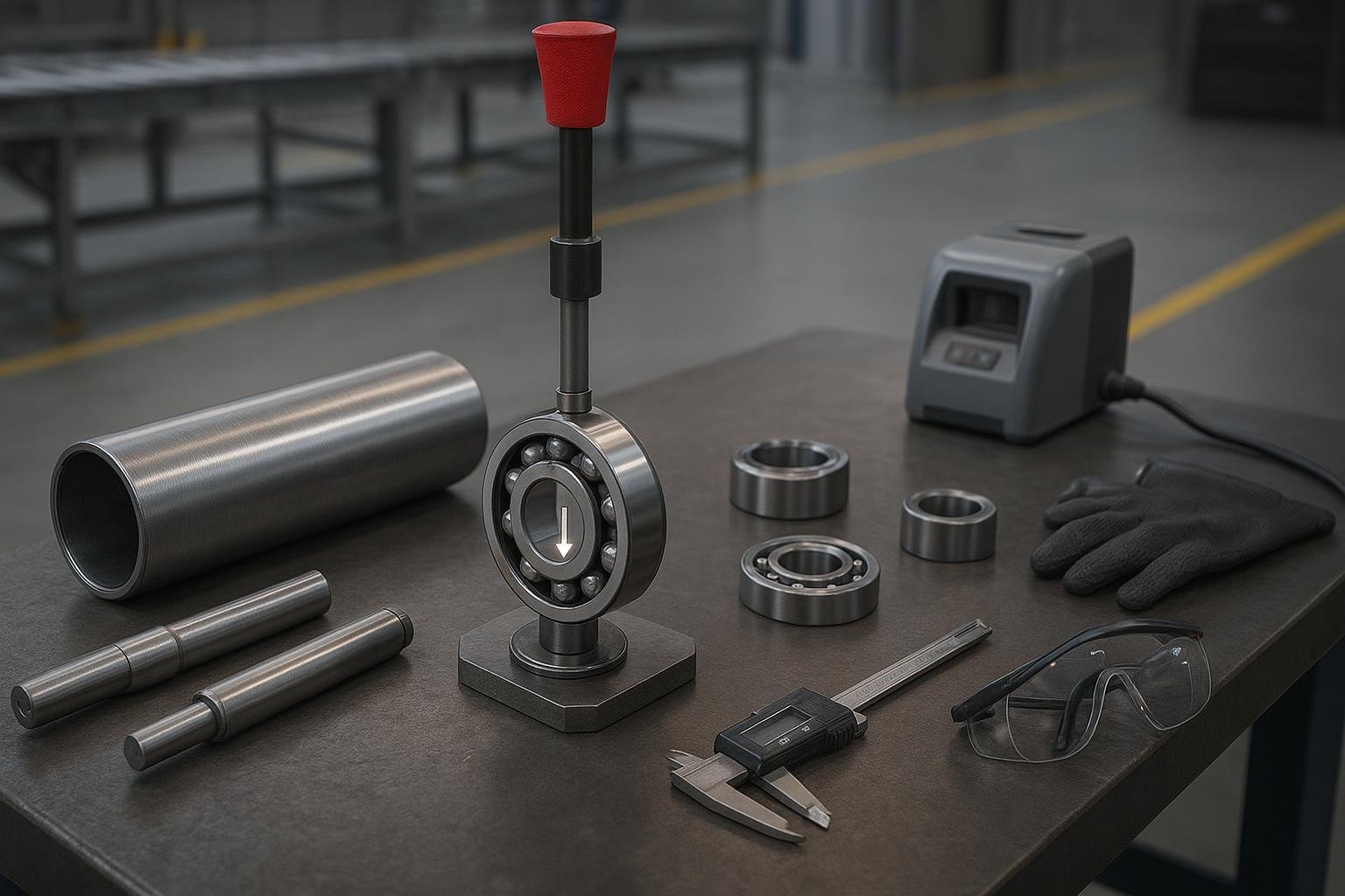
- Temperature: induction heater with temperature control and demagnetization, IR thermometer or contact probe, temp crayons
- Mounting: arbor or hydraulic press, press sleeves/mandrels and cups that contact the correct ring, soft jaws, retaining ring pliers
- Assembly: torque wrench and sockets, anti‑seize, light machine oil, approved grease and grease gun
Safety first: perform full LOTO before touching any conveyor components. Keep hands clear of pinch points at the press and when handling hot parts. Follow shop SOPs and ANSI/OSHA practices referenced by idler OEM manuals such as the PPI instructions.
Pre‑Install Inspections and Measurements
Before you reach for a press, measure and document. Bad seats or dirt will undo perfect technique.
- Clean and inspect the roller tube, shafts, and housings. Remove corrosion and burrs; repair or replace scored seats.
- Measure shaft seat diameter (where the inner ring mounts) at 3–4 clocked positions and along the width. Measure housing bore the same way. Record ambient shop temperature.
- Check shaft runout with a dial indicator; target ≤0.05 mm (0.002 in) TIR for typical idlers.
- Compare measured diameters to target fits guided by ISO 286 conventions and OEM tables. For rotating inner rings under normal loads, typical choices are:
- Shaft to inner ring: k6 or m5 interference/transition (size‑dependent)
- Housing bore to outer ring: H7 or J7 clearance/transition Representative ISO 286 deviations for common sizes (µm): shafts 30 mm k6 +10/+4, m5 +7/+4; holes 30–50 mm H7 0/+25, J7 −12/+15. See OEM fit tables aligned to ISO 286 such as SKF’s bearing interfaces and resultant fits pages.
According to SKF’s interfaces guidance, match the fit to load direction, temperature, and size; validate against the exact bearing and seat diameters you have on the bench. Sources: SKF bearing interfaces and resultant fits pages.
Choose Bearing, Seals, and Grease Wisely
- Internal radial clearance: Deep‑groove ball bearings with greater‑than‑Normal clearance (often C3) are commonly selected in dusty, shock‑prone conveyor service to accommodate interference fits and thermal effects. Always confirm against OEM clearance charts and your measured interference/temperature profile. See the discussion of internal clearance selection in the SKF Installation & Maintenance Guide and Timken engineering references.
- Sealing: In abrasive environments, pair contact‑sealed bearings (2RS) with an external labyrinth/dust‑cap stack in the roller end to improve ingress resistance. Multi‑labyrinth designs are common in heavy‑duty rollers (for example, Rulmeca notes labyrinth sealing on its PSV steel rollers).
- Grease: For general‑purpose idlers, NLGI 2 lithium‑complex or EP grease is typical. As a starting point, target roughly 30–50% of the free volume to limit churning heat at moderate speeds—consistent with OEM grease‑fill guidance ranges (see NSK grease lubrication guidance). Maintain grease chemistry consistency; avoid mixing incompatible thickeners.
References you can cite internally:
- SKF Bearing Installation & Maintenance Guide (clearance selection overview)
- NSK grease lubrication guidance (fill fraction by speed)
- Rulmeca PSV roller page (multi‑labyrinth mention)
The Golden Rule of Mounting Force
Apply force through the ring being fitted—never through the rolling elements. Press on the inner ring when mounting to a shaft; press on the outer ring when mounting into a housing. OEMs emphasize this because transmitting force through the balls causes brinelling and early failure.
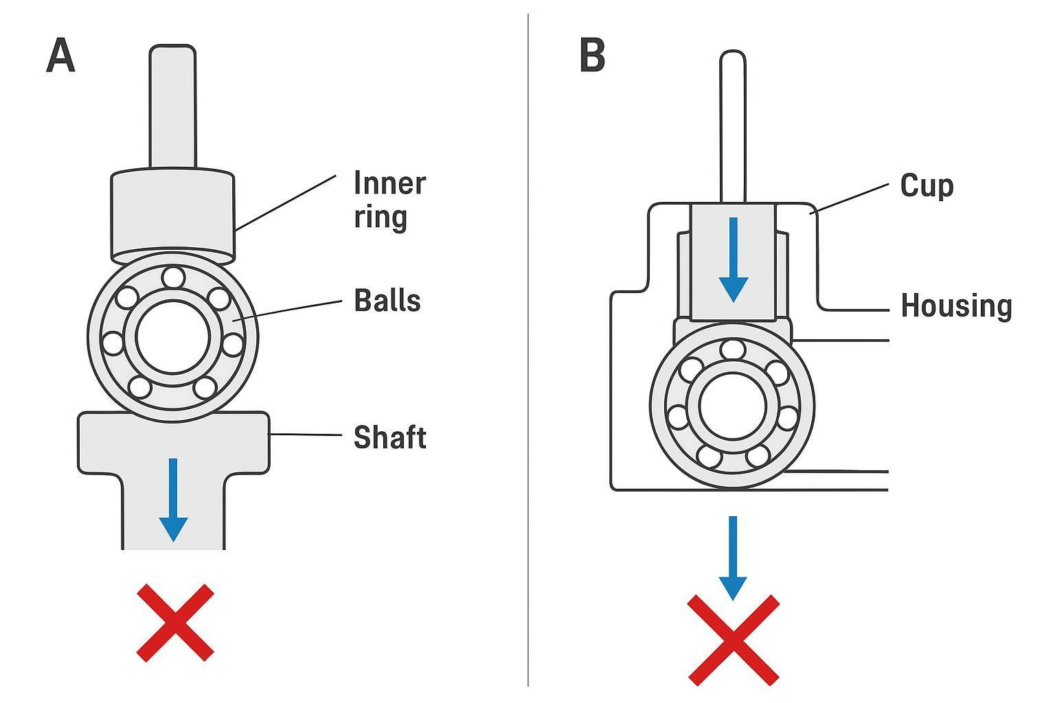
Authoritative guidance: NSK Handling Instructions define parallel, square pressing using the proper ring; SKF’s mounting resources repeat the same principle. See: NSK Handling Instructions for Bearings (E9010c) and SKF mounting pages.
Step‑by‑Step Conveyor Roller Bearing Installation
-
Lock out and tag out
- Isolate energy at the conveyor. Verify zero energy. Post danger tags.
-
Remove the roller and disassemble
- Lift safely; support the roller. Remove end caps, retaining rings, and seals. Extract old bearings with pullers or a press using ring‑specific tooling.
-
Clean and inspect
- Degrease components. Remove burrs with a fine stone/brush. Inspect for scoring, out‑of‑round, cracks. Replace or re‑machine damaged parts.
-
Measure seats and verify target fits
- Record shaft and bore diameters vs. nominal. Choose fits based on ISO 286 conventions and OEM tables (e.g., shaft k6/m5; housing H7/J7). Confirm you will maintain adequate residual clearance after mounting.
-
Prepare tools and environment
- Set press with the correct sleeves/cups that contact only the intended ring. Stage a flat, clean surface. Set the induction heater’s max temperature alarm.
-
Pre‑check bearing and seals
- Verify part numbers, internal clearance (CN/C3/C4), and seals (2RS or metal shields) match your plan. Rotate bearings by hand—no roughness, no noise.
-
Heat the inner ring when interference on the shaft is specified
- Use an induction heater; target roughly 80–110 °C (176–230 °F) per SKF electrical motor handbook cautions. Do not exceed the bearing/seal material limit. Use a probe or IR thermometer. Demagnetize after heating if your unit provides it to avoid attracting debris (NSK maintenance tools guidance).
-
Mount bearing on the shaft—force to the inner ring only
- With heated bearing or with light oil on a transition fit, slide/press the bearing squarely to the shaft shoulder. Use a mandrel that contacts only the inner ring. Do not hammer. Hold until seated and cool.
-
Mount the assembly into the roller housing—force to the outer ring only
- Align the bearing outer ring with the bore. Use a cup that contacts only the outer ring. Press squarely until seated against the housing shoulder/stop.
-
Build the seal stack and dust defenses
- Install internal spacers, labyrinth rings, and end caps as specified by the roller design. Ensure lip seals are evenly seated and not twisted. For multi‑labyrinth sets, verify each stage is clean and correctly oriented (drain paths clear).
- Check axial float or end‑play (if designed)
- Some idler designs use light axial float. Verify free axial movement or specified preload according to the assembly drawing.
- Grease appropriately
- If bearings are open or shielded and your design requires greasing, add NLGI 2 lithium‑complex or EP grease to approximately 30–50% of the free space (or per OEM). Avoid overfill that can cause churning heat.
- Spin and feel checks off the line
- Rotate by hand; feel for smoothness. The roller should coast down freely without gritty noise. Any binding suggests misalignment, contamination, or too‑tight fits.
- Install the idler frame and align on the conveyor
- Clean mounting surfaces. Loosely bolt the frame, square it to the belt centerline, and level across the width. Tighten bolts in sequence. Verify roller spacing per layout. Practical methods and sequences are documented in idler OEM manuals like PPI and Douglas.
- Run‑in and monitor temperature
- Start the belt at normal speed with a light load if possible. Use an IR thermometer to monitor the bearing area: expect stabilization around +10–40 °C (+18–72 °F) over ambient during initial run‑in per NTN‑SNR guidance. If temperature keeps rising or exceeds norms, stop and investigate.
Verification Checklist (Go/No‑Go)
- Seats cleaned, burr‑free; measured and recorded
- Fits selected per ISO‑aligned OEM tables; residual clearance expected acceptable
- Inner‑ring force for shaft mounting; outer‑ring force for housing mounting (no hammering)
- Induction heat used within ~80–110 °C; demagnetized; seals not overheated
- Seal stack installed cleanly; drain paths open; end caps secured
- Free rotation with no abnormal noise; axial float as designed
- Frame square and level; bolts torqued to spec; spacing verified
- Run‑in temperature rise plateaued within +10–40 °C over ambient
Troubleshooting: Symptoms, Likely Causes, Fast Fixes
-
Hot running soon after start‑up
- Likely causes: excessive interference/tight fit, over‑greasing, misalignment. Actions: verify seat sizes; reduce grease to recommended fill; realign frame. See SKF troubleshooting guidance on overheated housings.
-
Roughness or “gravelly” feel when spinning by hand
- Likely causes: force transmitted through balls during mounting (brinelling), contamination. Actions: replace bearing; review force‑application method per NSK/SKF; improve cleanliness.
-
Grease purge at seals
- Likely causes: overfill, incompatible grease thickeners. Actions: purge to correct level; standardize grease chemistry; consult NSK grease guidance.
-
Bearing creep or fretting marks on shaft/housing
- Likely causes: insufficient interference or out‑of‑round seats. Actions: re‑measure; choose tighter fit within ISO 286 options; repair seats.
-
Persistent temperature rise without plateau
- Likely causes: preload due to lost clearance, misalignment, contamination. Actions: re‑check fits, alignment; inspect/replace seals; replace bearing if damaged. NTN‑SNR notes typical stabilization ranges; deviation is a red flag.
Practical Example (Neutral)
In many quarry and cement applications, an idler roller is built around a deep‑groove ball bearing with C3 internal clearance, a contact 2RS seal, and an external labyrinth stack. For example, a roller assembly from BisonConvey can be specified with C3 deep‑groove bearings and multi‑stage labyrinth components to support dust exclusion when assembled per this guide. The key is not the brand name but the method: correct fits, controlled heating/pressing, clean seal assembly, and disciplined run‑in.
Citations and Further Reading
- Mounting force and handling: See NSK’s Handling Instructions for Bearings (E9010c) and SKF’s mounting overview.
- Heating limits and demagnetization: SKF’s Bearing Handbook for Electric Motors; NSK Bearing Maintenance Tools.
- Fits and tolerances: SKF bearing interfaces and tolerances and resultant fits; Timken catalogs align with ISO 286.
- Grease fill and compatibility: NSK Grease Lubrication; overview on compatibility considerations via industry references.
- Idler alignment and installation: PPI Belt Conveyor Idler Instructions; Douglas SOMM_Idler; alignment importance per Martin Idler Aligner.
- Failure modes and remedies: Schaeffler/Barden Bearing Failures; NSK Bearing Doctor.
Quick Reference Table: Representative Fits (ISO 286 context)
The following fit examples illustrate common targets for idler‑type applications. Always confirm with OEM tables for your exact diameters and loads.
| Interface | Typical fit | Representative deviation (µm) |
|---|---|---|
| 30 mm shaft to inner ring | k6 | +10 / +4 |
| 30 mm shaft to inner ring | m5 | +7 / +4 |
| 30–50 mm housing bore to outer ring | H7 | 0 / +25 |
| 30–50 mm housing bore to outer ring | J7 | −12 / +15 |
Use these as a sanity check alongside measured diameters and temperature effects.
Wrap‑Up
Conveyor roller bearing installation succeeds when you control five things: clean seats, correct fits, ring‑specific force paths, temperature, and sealing/lube discipline. Follow the checklist, cite the OEM tables, and verify with a short run‑in and temperature watch. If your shop lacks internal references on fits, clearance selection, or induction‑heating SOPs, add them to your maintenance library so every technician can repeat the process the same way, every time.