Getting a conveyor to move the right amount of material—without overloading the drive or spilling at the edges—starts with a solid grasp of “load.” In this beginner’s guide, you’ll learn how capacity, belt speed, power, and tensions fit together, and how to run first‑pass numbers you can refine later with standards or software.
We’ll reference recognized methods from ISO, DIN, and CEMA so you know where the formulas come from and where to go deeper when your project grows.
What “load” means on a belt conveyor
Conveyors carry bulk material as a moving cross‑section on the belt. Two ways to express “load” are useful:
- Mass flow (capacity): how many tons per hour (t/h or TPH) the system moves.
- Load per unit length: how many kilograms per meter (kg/m) or pounds per foot (lb/ft) sit on the belt at any instant.
Key variables you’ll see throughout:
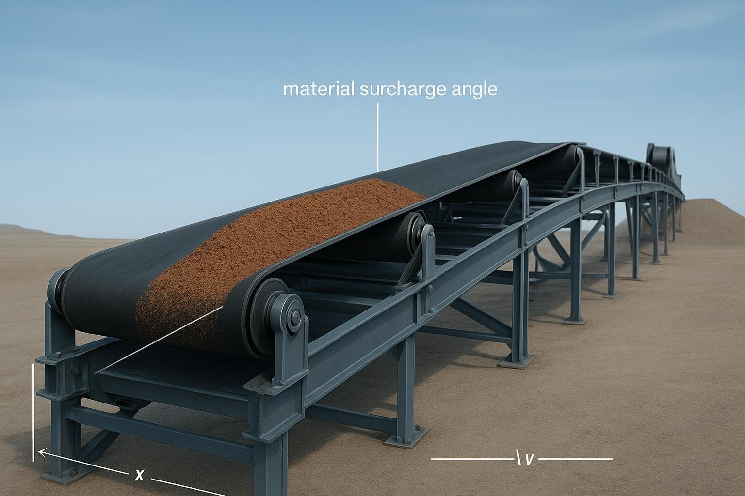
- Cross‑sectional area At (m² or ft²): the loaded area of material on the belt (depends on belt width, troughing angle, and the material’s dynamic pile shape).
- Belt speed v (m/s or fpm): linear speed of the belt.
- Bulk density δ (kg/m³ or lb/ft³): density of the material as it sits on the belt (bulk, not particle density).
- Surcharge angle λ (degrees): the dynamic slope the material makes on the moving belt; typically a few degrees lower than the static angle of repose.
- Troughing angle β (degrees): the idler angle (e.g., 20°, 35°, 45°) that shapes the cross‑section.
Why emphasize standards? Because methods and nomenclature differ a bit. ISO 5048 and DIN 22101 model resistances with an f‑factor and calculate operating power and tensile forces at the drive; CEMA (the “Belt Book”) uses K‑factors and the Te/T1/T2 tension framework. See the overviews at the official pages for ISO 5048 (scope: calculation of operating power and tensile forces) and DIN 22101 (design of belt conveyors for loose bulk materials), and the CEMA Belt Conveyors for Bulk Materials, 7th ed. store page.
Step 1 — Capacity from area, speed, and density
At its simplest, capacity is area × speed × density, with a unit conversion constant.
Metric (ISO/DIN style):
Qt (t/h) = 3600 × At (m²) × v (m/s) × δ (kg/m³) × K
- K is a fill/slope correction when used; for beginner estimates, many examples set K ≈ 1 if area already reflects the surcharge shape.
Imperial (CEMA style):
TPH ≈ A (ft²) × V (fpm) × D (lb/ft³) × 0.029
- The 0.029 factor handles unit conversion; some quick charts round to 0.03, but use 0.029 for cleaner math.
About At (loaded area): On troughed belts, At comes from geometry: a central segment plus two side segments shaped by β and λ. Rather than trying to derive it from scratch, beginners should consult CEMA tables or reputable calculation booklets. A helpful primer is the Forbo calculation booklet (beginner formulas), which walks through units and concepts.
Quick metric example (troughed belt):
- Suppose you have a 1000 mm belt with 35° troughing and a material with λ ≈ 25°. From a table (or software), you read At ≈ 0.075 m² (illustrative). Your material has δ = 1600 kg/m³ and you’re targeting Qt = 400 t/h. Solve for the speed needed:
v = Qt / (3600 × At × δ) = 400 / (3600 × 0.075 × 1600) ≈ 0.37 m/s
That’s a slow belt; in practice you might use a higher v and accept a lower fill to reduce spillage risk. The point is the relationships: higher area or density means you can run slower; lower area or density pushes speed up.
Practical input tips: Use bulk density under operating moisture/gradation (not particle density), pick At conservatively from tables while keeping edge distance, and measure speed with a tachometer or by timing a marked distance. These small habits keep first‑pass estimates believable.
For standards alignment: ISO/DIN formulations treat this as the volumetric starting point and fold it into resistance/power later; see the ISO and DIN overviews cited earlier.
Step 2 — Belt speed from a target capacity
Sometimes you’re told “we need 600 TPH” and must pick a speed. Just invert the capacity formula.
Metric:
v (m/s) = Qt / (3600 × At × δ × K)
Indicative speed ranges help sanity‑check results: many bulk conveyors run around 1–7.5 m/s. High speeds raise dust and spillage risks, especially with fine or low‑λ materials and large lump sizes. For methodology comparisons and where modeling differs, see Helix Delta‑T calculation methods (ISO/DIN/CEMA overview).
Imperial quick example (flat belt, known A):
- A = 0.5 ft², D = 60 lb/ft³, target TPH = 300.
V (fpm) ≈ TPH / (A × D × 0.029) = 300 / (0.5 × 60 × 0.029) ≈ 344.8 fpm
Think of speed as your “throttle,” but governed by what the cross‑section can hold safely without spillage.
Step 3 — Power: resistances, lift, and efficiency
At the drive pulley, operating power is pull × speed divided by drivetrain efficiency. ISO/DIN often write it with Fu (effective pull); CEMA uses Te.
SI form:
PM (W) = Fu (N) × v (m/s) / η
Imperial form (CEMA):
hp ≈ (Te (lbf) × V (fpm)) / 33,000
Where do Fu/Te come from? Sum the running resistances plus any vertical lift:
- Main resistances along the length (rolling/indentation and belt/load flexure).
- Secondary/special resistances (skirt seals, cleaners, plows, pulleys, misalignment).
- Lift term if the conveyor rises: weight of load times elevation gain.
ISO/DIN often start with an effective friction factor f to capture length‑proportional losses. A simplified first estimate on a horizontal conveyor is:
Fu ≈ f × L × g × (m′G + m′R) + (Q × g × H) + Fsecondary
- L is conveyor length, g is 9.81 m/s², m′G is belt mass per meter, m′R is rotating parts mass per meter that the belt “drags,” Q is load per meter, H is vertical lift (m), and Fsecondary lumps accessory losses. Typical well‑aligned f might range roughly 0.016–0.03, with higher values under poor conditions.
Worked metric estimate (f‑factor):
- Suppose Qt = 400 t/h and v = 1.4 m/s. Then load per meter is:
Q (kg/m) = (0.278 × Qt)/v = (0.278 × 400)/1.4 ≈ 79.4 kg/m
- Let L = 120 m, H = 8 m, m′G + m′R ≈ 40 kg/m, f = 0.025, η = 0.92, and assume Fsecondary ≈ 0.
Main resistance:
FH ≈ f × L × g × (m′G + m′R + Q)
   ≈ 0.025 × 120 × 9.81 × (40 + 79.4) ≈ 3,523 N
Lift resistance:
Flift = Q × g × H ≈ 79.4 × 9.81 × 8 ≈ 6,227 N
Fu ≈ 3,523 + 6,227 = 9,750 N → Power:
PM ≈ Fu × v / η ≈ 9,750 × 1.4 / 0.92 ≈ 14,850 W ≈ 14.9 kW
This is a first‑pass number. A thorough check will add accessory losses and validate f using idler data and alignment quality. For an inclined conveyor pull and power breakdown in practice, see Rulmeca’s technical explainer on belt pull and power (2023). For the standards’ scope on power/tension calculations, consult the overviews cited earlier.
Step 4 — Tensions in brief: T1, T2, and checks
CEMA frames tensions as:
- Te (effective tension) is what the drive must overcome.
- T1 is tight‑side tension; T2 is slack‑side tension at the drive pulley.
- Roughly, Te ≈ T1 − T2, with belt wrap and friction determining how much torque transfers without slip. Minimum T2 and sag criteria prevent idler “trampling” and tracking issues.
As you move beyond a quick estimate, consult the CEMA Belt Book (7th ed.) for tension breakdowns (Kx, Ky, temperature effects, cleaners) and safety/starting factors.
Micro‑example: how idlers shift your power estimate
Disclosure: BisonConvey is our product.
Imagine you’re estimating power for a 200‑m belt running 2.0 m/s at 600 t/h. Your first pass uses f = 0.030 based on mixed idlers and spotty alignment, returning roughly 40 kW. After a field audit, you select a consistent trough set with precision‑sealed bearings and improved alignment; your justified estimate drops to f = 0.022. Keeping everything else equal, main resistance scales with f × L × (m′ + Q), so the operating power falls about 27% in the estimate. The plant’s actual savings will depend on conditions and maintenance, but the math shows why idler quality and alignment matter. BisonConvey’s idler range can be used to support this type of engineering choice; if you’re comparing options, we can share data needed to backfill f or CEMA K‑factors.
Common mistakes and quick checks
- Mixing units or using particle density instead of bulk density → capacity and power come out wrong. Standardize units before you start.
- Assuming area from belt width alone → spillage at speed. Use CEMA area tables or software with β and λ accounted for.
- Ignoring lift or accessories (cleaners, skirts, plows) → underestimates Te/Fu. Add secondary losses or use K‑factors/f‑factors that reflect reality.
- Skipping slack‑side and sag checks → slippage and tracking trouble. Confirm minimum T2 and take‑up force.
- Overlooking alignment and idler condition → higher f/Kx, higher power. Audit alignment and roller rotation.
Caution: First‑pass f or K‑factor assumptions are convenient, but they hide real‑world variability from idler spacing, seal drag, temperature, and belt cover indentation. When the project is capital‑critical or long overland, move to a standard‑based, component‑level calculation or software model before specifying the drive.
Glossary & formula cheat sheet
Below is a compact reference. For full methods and definitions, see the official overviews of ISO 5048, DIN 22101, the CEMA Belt Book, and the beginner‑friendly Forbo calculation booklet cited above.
| Term | What it means | Typical units | Core relation |
|---|---|---|---|
| At | Loaded cross‑sectional area (depends on belt width, β, λ) | m², ft² | Qt = 3600 × At × v × δ × K (SI) |
| v | Belt speed | m/s, fpm | v = Qt / (3600 × At × δ × K) (SI) |
| δ | Bulk density of the conveyed material | kg/m³, lb/ft³ | In capacity formulas above |
| Qt/TPH | Mass flow (capacity) | t/h, TPH | TPH ≈ A × V × D × 0.029 (imperial) |
| Q | Load per unit length | kg/m, lb/ft | Q ≈ (0.278 × Qt)/v (SI); ≈ (0.1237 × TPH)/V (imp.) |
| Fu/Te | Effective pull (ISO/DIN/CEMA notation) | N, lbf | Power: PM = Fu × v / η (SI); hp ≈ Te × V / 33,000 (imp.) |
| η | Drivetrain efficiency | — | Divide power by η to account for losses |
What to do next
If you’re estimating a new or modified line, start by nailing the inputs: bulk density under operating conditions, a realistic loaded area from a recognized table, and a measured or targeted speed. Then choose a calculation path (ISO/DIN or CEMA) and be explicit about assumptions for friction and accessories. When you’re ready to turn a first‑pass estimate into a design, consult the standards and, if needed, software like Helix or Belt Analyst.
Want application‑driven help selecting belts, idlers, or pulleys and validating friction assumptions? BisonConvey can support with data sheets and selection guidance tailored to your duty and geometry. Reach out with belt width, strength class, length, lift, material, and target capacity, and we’ll respond with objective options—no fluff, just numbers.