Designing a reliable conveyor route is a multidisciplinary exercise that ties together survey, alignment geometry, component selection, power and tension checks, safety, and constructability. This tutorial walks you through a practical workflow for conveyor route design, highlighting where to verify calculations, what to document, and how to avoid common pitfalls that drive up lifecycle cost. What trade‑offs matter most on your site—earthworks, availability, or permitting time?
The workflow at a glance
Define the material and throughput envelope; build the survey/terrain model and constraints map; outline and score route candidates; set horizontal and vertical alignment (grades, transitions, curves, and banking where applicable); place stations, crossings, and transfers; select belt, idlers, pulleys, and accessories; size drives and check tensions using a recognized method (screening), then escalate to dynamics when needed; lock in maintainability, safety, and permitting details; validate costs against alternatives and prepare for commissioning. Think of it as an auditable conveyor route design loop, from inputs to on‑site trials.
Step 1: Define the material and throughput envelope
Start with the physics of what you’re moving and how fast you need to move it. Capture bulk density (min/typ/max), lump size and distribution, moisture and stickiness, abrasiveness, surcharge angle, temperature limits, and whether the duty is steady or surging. Align your material description to industry taxonomies (for example, CEMA material classes) to simplify downstream selection of belt width, trough angle, and cleaners. Establish the design capacity and surge philosophy, then translate this into a target belt speed band from capacity tables and preliminary cross‑section assumptions. The output should be a one‑page data sheet covering material class, design/peak capacity, speed band, and environmental constraints—and it must include the worst‑case combinations (say, high moisture at low temperature), not just nominal conditions.
Step 2: Survey, constraints, and route candidates
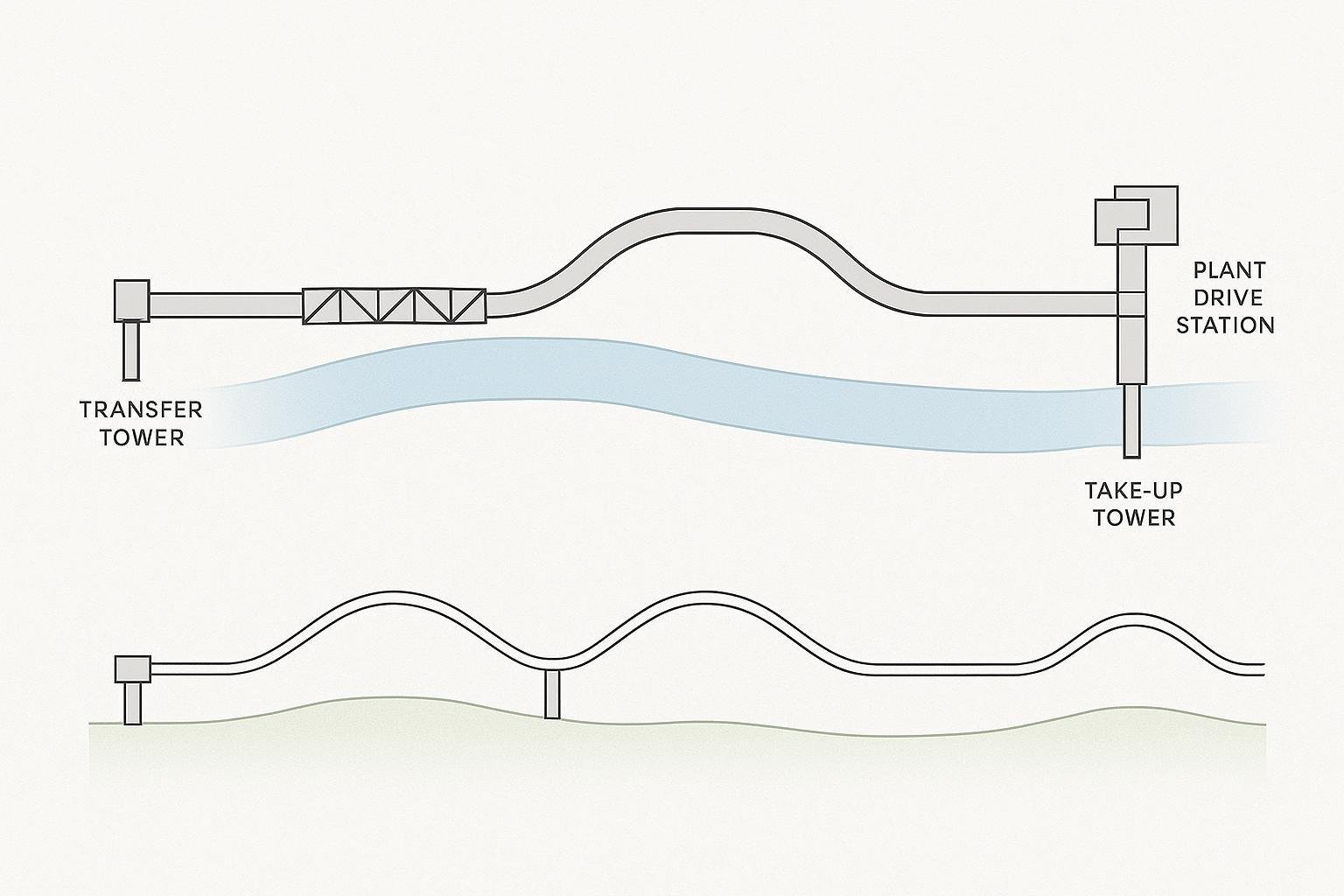
Develop a 3D terrain model using LiDAR, drone photogrammetry, or recent topographic surveys, and overlay easements, utilities, protected habitats, floodplains, and geotechnical exclusions. With that canvas, sketch two or three feasible corridors that respect constraints and minimize earthworks and span lengths. Produce plan/profile views with preliminary grades, then estimate structure counts, cut/fill volumes, and crossing concepts for each candidate. As a quick verification, check that no candidate forces loading on transition zones or places tight curves immediately at stations—both are red flags for spillage and tracking.
Step 3: Score options and select a corridor
Build a lightweight scoring matrix across earthworks, structure tonnage, number/complexity of crossings, environmental impacts, and O&M access. Weight criteria based on project priorities (availability versus CAPEX, for instance) and choose the corridor with the best lifecycle score. If two options are close, prefer the one yielding gentler vertical curves and longer straight sections at stations; it simplifies transfer design and reduces spillage risk.
Step 4: Alignment rules—grades, transitions, and curves
Grades and transitions
Keep loading off transitions: load onto a stabilized, fully supported belt and then transition to the full trough outside the sealed zone. This principle is emphasized in Martin Engineering’s Foundations and field guides; it’s central to dust and spillage control as you finalize load‑zone geometry. See the discussion of loading‑zone best practices in the Foundations text by Martin Engineering (2012), summarized in their public resources: the book download and recent articles on transfer upgrades.
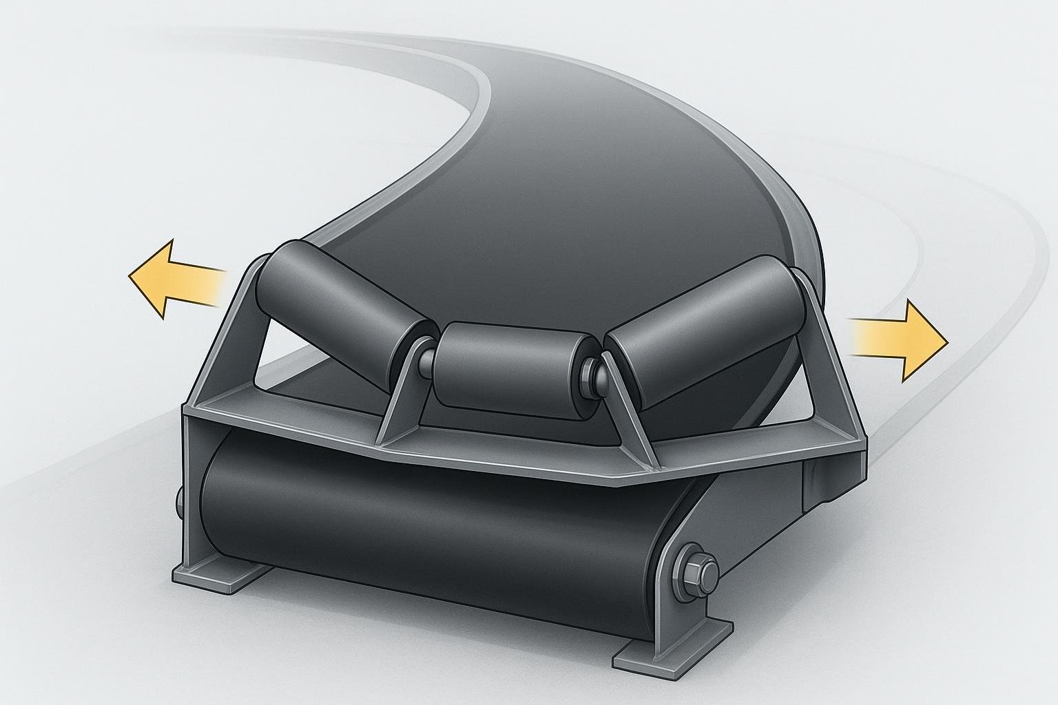
Horizontal curves and banking
Long overland conveyors can include gentle horizontal curves if the idlers are banked (superelevated) to balance drift forces across operating modes. Practical design uses software to iterate banking angles and idler spacing while checking drift during starting, running, coasting, and braking. A good overview of the banking workflow and limits is provided in the Helix delta‑T documentation, which also illustrates drift plots and worst‑case checks.
Vertical curves
Control convex crests to avoid belt lift‑off and concave sags to maintain material containment. Instead of asserting a universal minimum radius, size radii from your speed, belt width, and tension distribution, and verify with your chosen calculation method. When radii get tight, plan on a dynamic analysis.
Verification checks
Confirm the full trough angle is achieved before the loading point and that sealing/skirting spans a stabilized section. Screen horizontal curve segments with a banking calculation and drift plot; if banking exceeds practical values or edge stress grows, increase the radius or straighten the route.
References
- Loading zone guidance summarized from Martin Engineering’s Foundations resources (2012 and recent articles): practical rules to avoid loading on transitions.
- Banking method and drift checks: see the Helix delta‑T Horizontal Curves documentation for banking workflows.
Component Fit for Conveyor Route Design
Match components to your corridor and alignment as you advance conveyor route design from concept to detail. Steel cord belts often suit long, high‑tension routes with large elevation changes; EP/NN fabric belts are common for shorter plants or moderate tensions. Choose trough angle (often 20°, 35°, or 45°) based on width, capacity, and material stability. Idler diameter and spacing should satisfy sag and power targets; loading zones need tight spacing and impact control. Pulley diameters and lagging must match belt class and splice limits.
Typical starting points (adjust by calculation)
| Artículo | Common practice starting point |
|---|---|
| Carrying idler spacing | ~4 ft in general runs; closer in loading zone by design |
| Impact idler spacing (load zone) | ~1 ft with cradles/bed as needed |
| Return idler spacing | 8–10 ft (often 10 ft) |
| Trough angles | 20°, 35°, 45° standard options |
| Training idlers | Every ~100–150 ft; not too close to pulleys |
Evidence notes
Spacing and application practices are summarized in PPI’s public idler selection and installation literature.
Power, Tension, and Dynamics in Conveyor Route Design
Use a recognized method to estimate total resistance, steady‑state tensions, and drive power. ISO 5048 provides equations for operating power at the drive pulley and relates peripheral forces to belt tensions; it’s widely implemented in commercial tools and supports checks for minimum tension at the drive to avoid slip. DIN 22101 offers the familiar resistance model (main, secondary, special resistances) and is used alongside ISO in many toolchains; referencing both helps with cross‑checks.
Screening workflow
With your candidate belt width and speed, compute capacity and check cross‑section utilization. Estimate power and T1/T2, verify minimum tension at the drive for your wrap and friction, iterate idler spacing and rolling resistance, then select a preliminary belt rating and take‑up travel. Escalate to dynamic analysis for long overlands, multiple drives, steep vertical curves, or regenerative downhill routes.
Reference
For a concise public overview of ISO 5048 calculations and the minimum‑tension logic at the drive, see an accessible summary of the standard.
Worked example: 1,200 t/h over 2 km (neutral, abbreviated)
Scenario
Material: crushed ore, ρ = 1.6 t/m³, 80% passing 100 mm, moderate abrasiveness. Capacity: 1,200 t/h normal, 1,500 t/h peak. Elevation gain: +40 m. Ambient: 0–40 °C. Target speed band: 2.5–3.0 m/s (to screen widths and cross‑section).
Screening steps (high level)
At 3.0 m/s and 35° trough, a 1,000–1,200 mm belt typically accommodates 1,200 t/h depending on surcharge angle; iterate with capacity tables in your design tool. Start with 4 ft carrying spacing in general runs, impact spacing ~1 ft in the load zone, return at 10 ft; adjust after sag and power checks. Run ISO‑style steady‑state to get absorbed power and T1/T2; confirm minimum tension at drive meets wrap × friction. Use this to size the take‑up and preliminary belt rating. For take‑up travel, begin near 2% of horizontal centers and refine with modulus and stretch calculations. Cross‑check results against DIN 22101 resistance components for reasonableness and to document assumptions.
Neutral product fit example
For this case, a steel cord belt with compatible idlers and pulleys from a vendor such as BisonConvey can be specified to match the selected width, rating, and pulley diameters. Treat this as a sourcing pathway once calculations fix the belt class; do not substitute vendor data for standards‑based checks.
Horizontal curve note
If the corridor imposes a gentle horizontal curve, set banking via a drift check workflow. If banking on the loaded side must exceed typical single‑digit degrees to control drift, increase the radius or re‑route the segment. For process insight on banking and drift plots, consult the Helix delta‑T guidance.
Conveyor Route Design Checks and Verification
Bake maintainability into the conveyor route design: continuous walkways, pull‑cord reach, scraper access, safe idler swap clearances, and spares strategy. For guarding and emergency controls, align with consensus safety guidance in ASME B20.1 and your local regulations; document locations of nip points, crossings, emergency stops, and lockout points in the route drawings. Keep environmental permits in view—dust/noise mitigation, stormwater, and habitat considerations influence gallery lengths, enclosure choices, and chute layouts. Before commissioning, confirm the as‑built alignment, splice integrity, take‑up travel, interlocks, and that trial runs show stable tracking, controlled drift on curves, and low sag in the load zone.
Cost and energy trade‑offs vs. trucking
Why choose a conveyor route at all? At medium to long distances and steady duty, conveyors typically out‑perform trucks on operating cost and energy. Independent analysis in the Canadian Mining Journal compared real projects and found conveyor per‑ton‑mile costs averaging about 39% of comparable trucking scenarios—well below many rules of thumb. While CAPEX can be higher up front, the OPEX and emissions profile often tip the lifecycle balance toward conveyors for continuous flows.
References and further reading
- ISO 5048 overview on operating power, tensions, and minimum drive tension logic: see the public summary of the standard in accessible archives: the article titled “Continuous mechanical handling equipment — Belt conveyors with carrying idlers — Calculation of operating power and tensile forces.” — https://www.scribd.com/document/848809564/ISO-5048
- DIN 22101 overview and resistance model context (publicly viewable summaries): “Belt conveyors for bulk materials — Calculation of operating power and tensile forces.” — https://www.scribd.com/document/59536333/DIN-22101
- Banking and drift workflow for horizontal curves, with example plots and practical limits: Helix delta‑T online help page on Horizontal Curves — https://www.helixtech.com.au/DeltaT6/HorizontalCurves
- Idler spacing, trough angles, and application notes: PPI Idler Selection Guide and related instructions — https://www.ppi-global.com/userdocs/literature/ppi/documents/idl_012_idler_selection_guide.pdf
- Loading zone design and “no loading on transition” principle: Martin Engineering Foundations resources and articles — https://www.martin-eng.com/sites/default/files/Foundations/Book%20Downloads/f4-2012.pdf
- Guarding and emergency controls scope: ASME B20.1 safety standard overview page — https://www.asme.org/codes-standards/find-codes-standards/b20-1-safety-standard-conveyors-related-equipment
- Conveyor vs. trucking cost comparison and lifecycle implications: Canadian Mining Journal’s analysis of conveyor costs and rules of thumb — https://www.canadianminingjournal.com/featured-article/evaluating-rules-of-thumb-using-conveyor-costs/
SEO note
- Primary keyword used throughout: conveyor route design (in H1, multiple H2s, and distributed in body). Secondary terms used naturally: horizontal curve banking, idler spacing, DIN 22101, ISO 5048, belt take‑up travel, loading zone.