
Verifying conveyor roller (idler) load capacity is about proving—on paper and in practice—that each idler can carry the loads you’ll apply, for as long as you need, under real site conditions. This guide focuses on troughing, return, impact, and training idlers used on bulk-material belt conveyors. We’ll work through inputs, calculations, and acceptance criteria so your decisions stand up to scrutiny and field reality.
Note on standards: Use the methodology from CEMA and ISO where applicable. For bearing life, reference ISO 281 (L10 life). For idler geometry and classes, consult CEMA Belt Conveyors for Bulk Materials (7th Ed.) and CEMA Standard No. 502. For contamination, temperature, and reliability corrections to bearing life, rely on bearing OEM handbooks (SKF, NSK, NTN). Where a numeric limit depends on a table (e.g., load distribution by trough angle or sag criteria), consult the cited documents rather than guessing values.
Preparation checklist for your calculation
Gather these before you start. Keeping units consistent (SI recommended) will save you headaches.
- Conveyor and belt: belt width, belt speed, trough angle, idler spacing (carry/return), belt mass per length, sag target/criteria
- Material and loading: bulk density, surcharge angle, normal loading cross‑section, carryback assumption, duty cycle
- Idler details: idler type (troughing 3‑ or 5‑roll, return, impact, training), roller diameter and face length, tube OD and wall thickness, shaft diameter and span, bearing type/series with dynamic (C) and static (C0) ratings, sealing type
- Environment: temperature range, water/moisture, dust level, chemicals/corrosion, cleanliness/contamination level
- Special zones: impact zone data (drop height, lump size, impact coefficient), misalignment risk, heat exposure
Tip: Build a one‑page input sheet for each conveyor section so assumptions are easy to audit.
Verify conveyor roller load capacity: the workflow
1) Calculate load per idler and per roll
- Compute linear mass: m_total = m_belt + m_material (kg/m).
- Carry side load per idler: W_idler = m_total × g × s, where g ≈ 9.81 m/s² and s is idler spacing (m).
- Return side load per idler: W_ret = (m_belt + m_carryback) × g × s.
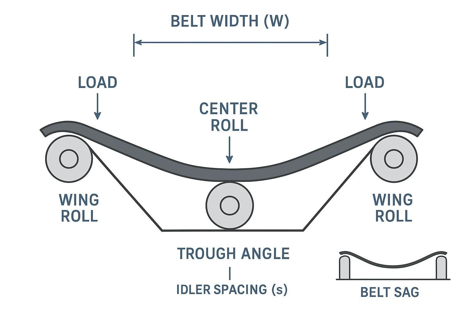
- Distribute W_idler across rolls based on trough angle and idler configuration (3‑roll or 5‑roll). The center roll typically carries the largest share; wing rolls share the remainder. Use distribution percentages from CEMA tables or reputable manufacturer guides.
2) Convert belt speed to idler RPM
- Idler RPM = (V × 60) / (π × D), where V is belt speed (m/s) and D is roller diameter (m).
- Larger diameter lowers RPM for the same belt speed, which usually increases calculated bearing life for a given bearing capacity.
3) Check bearing dynamic life (ISO 281) and convert to hours
- ISO 281 basic rating life: L10 (revolutions) = (C / P)^p × 10^6, with p = 3 for ball bearings and p = 10/3 for roller bearings; C is dynamic capacity; P is equivalent dynamic bearing load.
- Convert to hours: L10h = L10 / (60 × RPM).
- Apply reliability and application corrections per bearing OEM guidance (often expressed as reliability factor a1 and application factor aISO that accounts for contamination, lubrication, and temperature). Document your chosen factors and source.
- Target life: pick a target L10h aligned to duty (for example, medium‑to‑heavy process conveyors often target tens of thousands of hours). Confirm with your site standards and OEM tables rather than using a generic number.
Authoritative reading on the method and factors: see ISO 281 summarizations by major bearing manufacturers and the standard itself.
4) Verify bearing static rating for shocks
- Compare maximum expected static and shock loads at the bearing to the bearing’s static capacity C0. Include impact coefficients where applicable (impact zones, start‑ups, jams).
- The goal is to avoid permanent deformation/brinelling under worst‑case static loads. Use OEM guidance for allowable limits and multipliers.
5) Check shaft deflection and bending stress
- Model the roller as a simply supported beam with distributed load and bearing reactions at the seats.
- Compute maximum deflection (δ_max) and bending stress (σ_b). Keep deflection small enough to protect seals and maintain alignment. Use conservative safety factors to yield and fatigue.
- Limit values depend on geometry and OEM limits; source recommended thresholds from CEMA/member guides or idler designers and apply them consistently.
6) Check shell (tube) stress and ovalization
- Estimate bending stress in the tube from the applied line load and span, considering tube OD and wall thickness. For thin‑wall tubes, also consider ovalization risk.
- Keep combined stresses below a conservative fraction of material yield and consider high‑cycle fatigue for 24/7 service. Follow manufacturer engineering notes for allowables.
7) Tie idler spacing to belt sag criterion
- Idler spacing drives both the load per idler and belt sag between idlers. Choose spacing to meet sag criteria on the carry and return sides while balancing bearing life and energy.
- Consult CEMA and manufacturer tables for recommended sag targets and how they relate to spacing by belt width, trough angle, and load.
8) Map results to a CEMA/ISO/DIN class
- Once the checks pass, map the selected idler to a class (e.g., CEMA B, C, D, E, F) or equivalent ISO/DIN series. Class implies typical dimensions (tube OD, shaft size, bearing size) and performance envelopes.
- If any check is marginal (e.g., L10h just above target, or deflection near limit), consider upsizing class, reducing spacing, or specifying impact/training idler types at problem locations.
Worked example: from inputs to pass/fail
Below is a simplified, internally consistent example to show the workflow. Replace values with your site data and consult the cited standards for exact limits and distributions.
Assume (carry side):
- Belt width: 1,000 mm; troughing idler, 3‑roll; trough angle per CEMA table
- Belt mass: 15 kg/m; material mass: 60 kg/m → m_total = 75 kg/m
- Idler spacing: s = 1.0 m; g = 9.81 m/s² → W_idler = 75 × 9.81 × 1.0 ≈ 736 N
- Distribution (use your CEMA‑sourced percentages): center roll largest share; wings divide remainder
- Roller diameter: D = 152 mm (0.152 m); belt speed V = 2.5 m/s → RPM = (2.5 × 60) / (π × 0.152) ≈ 314 rpm
- Bearing: deep‑groove ball bearing with C = 9.0 kN; equivalent dynamic load per bearing P estimated from roll load and geometry (illustrative): P = 1.8 kN
- ISO 281: L10 = (C/P)^3 × 10^6 = (9.0/1.8)^3 × 10^6 = 125 × 10^6 rev
- L10h = 125e6 / (60 × 314) ≈ 6,630 h before corrections
- Application/reliability corrections (illustrative only; use OEM tables): suppose combined factor reduces life by 0.6 → adjusted ≈ 3,980 h
- If site target is 50,000 h, this fails. Options: increase bearing size (C), increase roller diameter (lower RPM), reduce spacing (lower load per idler), or improve sealing/contamination control.
Now iterate once:
- Increase diameter to 178 mm (0.178 m) and specify a bearing with C = 14 kN; keep P similar initially for comparison.
- RPM = (2.5 × 60) / (π × 0.178) ≈ 268 rpm
- L10 = (14/1.8)^3 × 10^6 ≈ 335 × 10^6 rev → L10h ≈ 20,800 h (pre‑correction)
- With the same 0.6 correction → ≈ 12,500 h. Still short. Reduce spacing to 0.8 m so W_idler drops by 20% and P follows proportionally.
- If P drops to ~1.44 kN, then L10 = (14/1.44)^3 × 10^6 ≈ 660 × 10^6 rev → L10h ≈ 41,000 h pre‑correction → ~24,600 h corrected. May still be below a 50,000 h target; further changes (higher C bearing, improved sealing reducing correction, or a higher class idler) are justified.
Why show a “fail then fix” path? Because this is exactly how spacing, diameter, and bearing selection interact. Think of it as a three‑way lever: spacing sets the load; diameter sets RPM; bearing capacity sets the life curve.
A neutral product example for context
- If you pull a spec sheet for a troughing idler from a manufacturer like BisonConvey, you’ll typically find tube OD and thickness options, shaft sizes, and bearing series that align with CEMA classes. Those data let you compute P precisely (based on roll load paths) and select an appropriate bearing C and tube/shaft combination to meet your pass criteria. Use the published dimensions to populate your worksheet; don’t assume generic values.
Summary table (example values, not design limits)
| Item | Example result |
|---|---|
| Load per idler (carry) | 736 N at 1.0 m spacing |
| Idler RPM | ~314 rpm (152 mm) → ~268 rpm (178 mm) |
| Bearing life L10h (pre‑correction) | 6,630 h → 20,800 h → 41,000 h |
| Corrected L10h (illustrative 0.6 factor) | 3,980 h → 12,500 h → 24,600 h |
| Status vs 50,000 h target | Fail → Borderline → Still short (needs further upsizing/controls) |
Troubleshooting and quick field checks
-
Bearing temperatures creeping up after a few weeks of service
- Probable causes: higher‑than‑assumed load P, contamination raising drag, misalignment increasing seal friction.
- What to verify: measured belt speed vs design (RPM), contamination level, idler alignment, bearing specification vs calculation.
- Corrective actions: reduce spacing in hot zones, improve sealing/guards, upsize bearing/class where calculations are marginal.
-
Abnormal seal wear or grease purge
- Probable causes: excessive shaft deflection at the seats, poor sealing for environment, over‑greasing on certain designs.
- What to verify: deflection vs recommended limits; sealing type vs duty; installation tolerances.
- Corrective actions: stiffer shaft/tube, better seals/shields, confirm torque and mounting practices.
-
Dented or ovalized idler tubes near loading points
- Probable causes: under‑specified tube wall, high impact energy, oversized lumps vs design.
- What to verify: impact coefficients/energy, tube thickness vs allowable stress, presence/absence of impact idlers or beds.
- Corrective actions: specify impact idlers/beds, increase tube wall, shorten spacing within impact zone.
-
Belt sag visible beyond tolerance between idlers
- Probable causes: spacing too long for load/tension, low trough angle, low take‑up tension.
- What to verify: sag criterion for the section, spacing vs guidance, take‑up settings.
- Corrective actions: reduce spacing, adjust take‑up, review trough angle and loading profile.
Field check tip: Use IR thermography during steady state to trend idler bearing temperatures section by section; sudden outliers usually correlate with load or sealing problems.
FAQ: common what‑ifs
-
Do I need different calculations for return idlers?
- Loads are lower (belt plus carryback), spacing is often longer, and there’s no trough distribution. The verification steps are the same; the numbers change.
-
How do I account for very dusty or wet environments?
- Apply application/reliability corrections to bearing life per OEM guidance and consider sealing upgrades. Expect lower corrected L10h unless contamination is well controlled.
-
What about impact zones under feeders or chutes?
- Use impact idlers or impact beds and apply impact coefficients or energy‑based peak loads. Verify static C0 and tube/shaft stresses against those peaks.
-
When should I upsize the idler class?
- If any check is marginal—bearing life, deflection, shell stress, sag, or static rating—move up a CEMA class, shorten spacing, or increase diameter and bearing capacity.
Next steps
- Build or download a calculator that implements the steps above (inputs → load per idler/roll → RPM → ISO 281 life with corrections → deflection/stress → spacing and class mapping). If you’d like a worksheet prefilled with representative idler dimensions, you can request a spec sheet and example calculator from the manufacturer you’re sourcing from; for instance, the team at BisonConvey can provide product dimensions that plug directly into your verification sheet.
References for methodology and tables (consult for numeric limits and distributions):
- ISO 281 bearing life methodology and reliability/application factors via bearing OEM knowledge bases (e.g., SKF, NSK, NTN official handbooks and application guides).
- CEMA Belt Conveyors for Bulk Materials (7th Ed.) and CEMA Standard No. 502 for idler geometry, classes, spacing, and load distribution guidance.
- Public member resources that summarize CEMA guidance, such as idler selection notes published by established manufacturers.