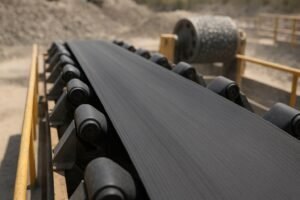
Loading zones are where belts live or die. High drop heights, sharp lumps, wet fines, and misaligned transfer chutes combine into a perfect storm of gouging, impact fatigue, and bearing contamination. From 2024 to 2026, the most meaningful changes in impact rollers (impact idlers) have clustered around materials and protection: lighter polymer/composite shells, corrosion-proof shafts, ceramic-reinforced contact surfaces in extreme abrasion, multi-stage seals with higher ingress resistance, and early-stage adoption of embedded sensors. The upshot for reliability and procurement teams: you have more levers to pull—but also more specs to verify.
Publicly available evidence still skews vendor-led. That means engineers should treat directional claims as starting points and request drawings, test methods, and field data for the exact products under consideration. The sections below connect the new options to practical outcomes you can audit on-site: wear behavior, seal life, retrofit fit-up, and total cost of ownership.
Quick Selection Matrix by Environment
Use this matrix as a first pass when shortlisting designs; it frames impact roller material engineering choices by dominant operating risks.
| Environment focus | Shell material | Shaft choice | Sealing architecture | Bearing notes | Sensor note |
|---|---|---|---|---|---|
| Dry, abrasive fines (cement, quarry) | UHMWPE/HPPE or composite shell; steel acceptable where corrosion is low | Carbon steel or stainless if washdowns occur | Labyrinth + contact lip + flinger (multi-stage) | Sealed deep-groove bearings with high-quality grease | Optional vibration/temperature sensing for early failure cues |
| Wet, sticky slurry (coal prep, beneficiation) | Polymer/composite shell (low adhesion); consider ceramic-reinforced surfaces on extremes | Stainless or non-metal/composite shaft to resist corrosion | Aggressive multi-stage seals; verify ingress testing; aim for IP67-like performance | Bearings rated for moisture; grease with good water resistance | Beneficial if failures are frequent; ensure gateway coverage |
| Saline/acidic atmospheres (ports, fertilizer) | Polymer/composite shell | Stainless (304/316/duplex) or non-metal shaft; verify hub interface protection | Multi-stage seals with corrosion-resistant components | Corrosion-resistant bearings and spacers; confirm coatings | Temperature/speed sensing helps trend corrosion-induced drag |
| Heavy impact with large lumps | Thicker polymer/composite shell or steel with impact rings; consider impact bed under chute | Steel or stainless; verify shaft strength and deflection | Robust seal stack with shields against mechanical damage | Larger bearing class; confirm dynamic load rating | Sensors usually lower priority unless failure history is high |
According to industry trend overviews, advanced polymers/composites and digital monitoring are gaining ground in mining-duty idlers, but quantified field deltas are often absent in public docs—treat them as prompts for site trials rather than guaranteed outcomes. See PROK’s forward look on polymers and monitoring in mining conveyors for context: the company outlines the direction of travel without prescriptive numbers in its 2024 innovation piece (PROK, 2024).
Materials Deep Dive: Polymers/Composites, Steel, and Ceramic Reinforcement
Polymers and composites. Non-metallic shells—UHMWPE/HPPE or composite tubes—are positioned for lower mass (easier change-outs), corrosion resistance, and favorable abrasion behavior. Publicly available pages outline these benefits but rarely publish third-party wear rates. For example, a vendor page on HPPE-based rollers emphasizes corrosion immunity and lightweight construction for harsh sites, but details like test methods and independent validations are limited in open literature (Global Conveyor Systems, 2025). Practically, lighter shells can reduce rotating inertia and reduce manual handling risk during change-outs, while polymer surfaces may shed sticky fines better than roughened steel.
Steel (baseline). Steel shells remain a robust default where corrosion is manageable and extreme weight reduction is not required. They pair predictably with standard frames and impact rings. In highly abrasive zones, steel can still perform well when combined with impact beds to spread load and reduce gouging. The trade-offs are susceptibility to corrosion and potentially higher noise and inertia compared with polymer/composite designs.
Ceramic reinforcement. Ceramics excel in abrasion resistance, which is why ceramic lagging is common on pulleys. Extending this logic to rollers is plausible for severe abrasion lanes, but engineers should avoid one-to-one extrapolations from pulley lagging to hollow roller shells without application-specific testing. A representative vendor page summarizes ceramic wear advantages on pulleys but does not document roller-shell implementations or test methods transferable to idlers (Kingcera, 2025). If considering ceramic-faced impact rollers, confirm shell/core bonding, impact resilience, and dynamic balance after reinforcement.
Trend framing. Mining-focused commentary points to advanced polymers/composites and sensing as “next-gen” idler attributes, useful for scoping trials and CAPEX planning even if numbers are sparse in public materials (PROK, 2024).
Takeaways you can act on now:
- For wet/corrosive zones, prioritize polymer/composite shells and either stainless or non-metal shafts. Guard the shaft–hub interface against crevice corrosion and verify torque transmission.
- Where impact is extreme, pair shell choice with chute design and impact beds to manage energy before it reaches bearings.
- If considering ceramic reinforcement on rollers, require supplier test data specific to impact roller geometry and loads.
Sealing and Bearing Protection: From Labyrinths to IP-rated Stacks
In loading zones, seal failure often precedes bearing failure. Multi-stage sealing stacks—labyrinth paths plus contact elements and external flingers—are widely referenced as best practice. Among public vendor documents, one of the clearer open descriptions appears on a non-metallic roller page that outlines seals, SKF bearing options, and operational characteristics, including references to mining certifications. It provides a useful template for how a stack can be arranged, even if it’s not a substitute for test reports (Langno, 2024).
What to verify with suppliers:
- Ingress resistance: Ask for test methods and results that mirror your environment—dry dust, wet fines, or slurry. If an IP rating is claimed (e.g., IP67/IP68), request the specific report and conditions.
- Grease management: Confirm grease type, re-lube policy (if any), and evidence of grease retention after cyclic temperature and washdown exposure.
- Bearing class and loading: Match dynamic load ratings to your impact zone calculations; ensure adequate internal clearances for temperature swings.
- Mechanical protection: In impact beds, shield the seals from direct strikes and debris to avoid lip damage.
A practical note: Even the best seal can be defeated by misalignment or damaged frames. Build a short inspection routine for seal lips, flingers, and end caps during shutdowns.
Sensor-Ready Idlers: Practical Use Cases and Data Paths
Sensors are moving from pilot to selective deployment. Two patterns dominate public documentation:
- Integrated smart-idlers that harvest rotational energy to power embedded sensing of temperature, vibration, RPM, and sometimes shell wear signatures. A co-branded overview describes self-powered monitoring and wireless data paths to gateways and PLC/cloud layers; it’s a good starting point for understanding modalities and architecture (PPI/Vayeron overview, 2020–2025).
- Idlers with integrated speed sensing that output pulses to a local monitor/PLC, typically via wired connections. A product sheet and monitor manual detail pulse rates, ranges, and wiring interfaces, clarifying where speed data can feed interlocks or analytics (PPI Smart Roll documentation, 2024).
Before scaling sensorization, verify:
- Power and maintenance: Is it self-powered or battery-driven? If batteries are used, what’s the replacement interval at your belt speed and ambient temperature?
- Environmental ratings: Temperature range, ingress protection, shock/vibration limits, and RF compliance.
- Data path and cybersecurity: Gateway density, protocol, latency, and how alarms integrate with your PLC/DCS.
- False positives: What filtering or enveloping methods are used to avoid nuisance alarms in high-impact zones?
When does it pay? If your loading zone burns through bearings or causes unscheduled stops, even a modest reduction in surprise failures can justify a targeted sensor deployment. Think of it as an insurance layer while you optimize sealing and chute design.
Retrofit and Standards Crosswalk (CEMA/DIN): Fit, Balance, and Safety
Most North American sites work to CEMA classes and dimensions; many international mines use DIN/ISO frameworks. For formal references to idler dimensions, balance, and testing, consult DIN 22112-1 (official catalog listing provides scope and edition details) (DIN 22112-1, 2010). For CEMA, pull the current editions from your standards library or the CEMA store before asserting interchangeability.
Retrofit checklist (use during walkdowns and RFQs):
- Measure frame dimensions and troughing angles; verify idler face width, shaft diameter, and end-cap clearances against drawings.
- Confirm dynamic balance class and allowable runout; request balance certificates for high-speed lines.
- Check axial load paths in impact beds; ensure seal stacks are protected from debris and direct strikes.
- Validate torque transmission at the shell–hub–shaft interfaces for polymer/composite designs.
- Align with lockout/tagout procedures and handling weights; lighter shells ease ergonomics but confirm lifting points and rigging.
Worked Example: Specifying a Corrosion-Exposed Impact Zone
Scenario: A port transfer point handles saline-laden fines and occasional wet lumps. The belt suffers from early bearing failures and rusted shafts in the first 30 meters after the chute.
Specification approach:
- Shell: UHMWPE/HPPE or composite shell to reduce corrosion and adhesion of wet fines.
- Shaft: 316 stainless or a non-metal/composite shaft; protect the hub interface with compatible sleeves or bushings to avoid crevice corrosion.
- Sealing: Multi-stage stack—labyrinth path, contact lip, and external flinger—with documented ingress testing under spray/salt conditions.
- Bearings: Sealed deep-groove units rated for moisture; water-resistant grease and verified internal clearances.
- Impact control: Impact bed under the chute to spread load; ensure skirting reduces turbulence.
- Monitoring: Add self-powered vibration/temperature sensing only on the first two impact sets where failures cluster; route alarms to PLC with time-stamped logs.
A number of manufacturers can support this configuration. For instance, an industrial supplier like BisonConvey can be engaged to source impact rollers with polymer shells, corrosion-resistant shafts, and multi-stage seals compatible with standard frames; selection should proceed via drawings, materials certificates, and test data review rather than brand claims.
Next Steps for Teams in 2026
To move from trend to specification, request auditable reports before locking in claims (abrasion testing for shells, ingress/IP results for seals, and corrosion trials for shafts and housings), run a short controlled field pilot in the first impact bed and instrument it for MTBR, start-up torque, and steady-state power draw, and maintain a dated change log as suppliers revise polymer grades, seal designs, or sensor firmware. Revisit your standards library quarterly to confirm current CEMA/DIN/ISO references when drafting RFQs and design updates. If you’re refreshing a spec this quarter, begin with the selection matrix above, shortlist two or three options per environment, and line up the drawings and tests needed to turn directional claims into site-proven data.