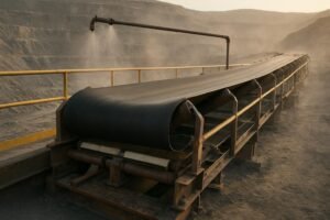
Corroded rollers don’t just look bad—they seize, shed fragments, contaminate product, and spike power draw. In coastal terminals, fertilizer plants, and wet processing lines, corrosion shortens mean time between replacements (MTBR) and drives unplanned stops. This guide focuses on reducing roller corrosion with choices you can specify today: materials and coatings that match the environment, sealing and bearing protection that actually keep water out, lubrication that resists salt, and inspection practices that catch issues before they snowball. Think of it as a practical playbook for uptime and total cost of ownership (TCO).
How conveyor roller corrosion actually happens
If you’re fighting “mystery” roller failures, here’s the deal: it’s rarely just one cause.
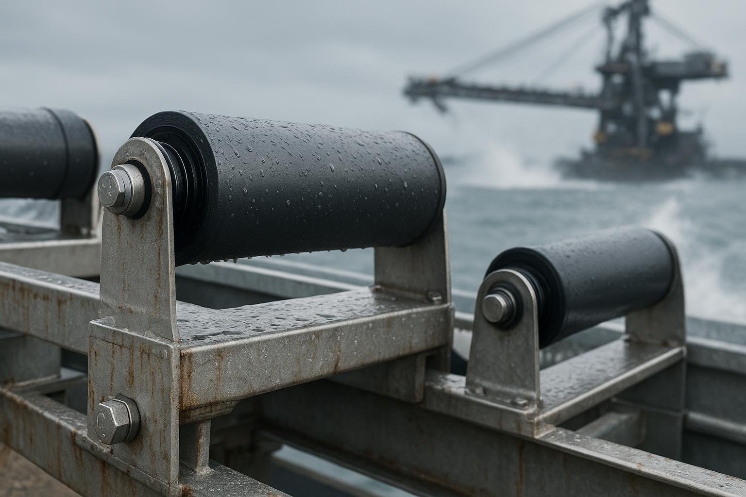
- Moisture and chlorides drive pitting and crevice corrosion, especially in C4–C5 marine exposures. The ISO system classifies atmospheric corrosivity levels from C1 to CX; use these categories to set protection levels according to the guidance in the official preview of ISO 9223 corrosivity categories and industry summaries.
- Chemical attack from fertilizers, acids, and alkalis undermines coatings and elastomers.
- Abrasive fines erode paint and seals, opening pathways for water ingress.
- Galvanic couples form where dissimilar metals touch in the presence of an electrolyte.
- Inadequate lubrication lets micro‑pitting start, and emulsified grease (milky) signals water entry that accelerates rusting.
Corrosion rarely stays on the surface—once seals are compromised, bearings corrode and fail. Break the chain at the material/coating and sealing stages to keep moisture out in the first place.
Choose materials and coatings that match your environment
Stainless, coated carbon steel, and engineered polymers
- 304 stainless works in low‑chloride atmospheres but pits quickly in marine splash.
- 316/316L improves chloride resistance but can still pit in seawater.
- Duplex 2205 offers significantly higher chloride pitting resistance and roughly double the yield strength of 304/316, enabling thinner sections in harsh marine zones. Practical design guidance is summarized by the Nickel Institute’s duplex overview and PREN rationale in this duplex stainless guide.
- Coated carbon steel is cost‑effective for C2–C4 if the coating system is appropriate and maintained.
- UHMWPE or HDPE sleeves/rollers are immune to red rust; they reduce carryback adhesion and can be compelling on the return side in wet, abrasive service.
Galvanizing, paints, epoxy, and thermal sprays
- Hot‑dip galvanizing (HDG) per ASTM A123 provides a zinc barrier/sacrificial layer. Thickness depends on steel category and section; see the specification and engineering notes in ASTM A123 guidance. Service life ties back to zinc loss rates by ISO corrosivity category; the American Galvanizers Association summarizes typical rates by C‑class.
- In C5/CX, duplex systems (HDG plus epoxy/polyurethane) or high‑build epoxies outperform paint alone. Thermal‑spray zinc/aluminum with seal coats is another durable path where impact allows.
- Salt‑spray (ASTM B117) is useful for comparative screening, but it does not predict field life by itself; cyclic tests closer to ISO 12944 service are better. See limitations discussed in Sherwin‑Williams’ B117 overview.
Quick comparison: materials and coatings
| Option | Strengths | Limits/Notes | Typical use |
|---|---|---|---|
| 304 stainless | General corrosion resistance; availability | Susceptible to chloride pitting | C2–C3 frames, dry plants |
| 316/316L stainless | Better chloride resistance than 304 | Can still pit in seawater | C4 coastal frames, washdown areas |
| Duplex 2205 stainless | High pitting resistance and strength | Higher cost; fabrication care | C5/CX marine splash, critical structures |
| HDG carbon steel | Cost‑effective sacrificial coating | Faster zinc loss in C5/CX | C2–C4 rollers/frames, then overcoat |
| Epoxy/polyurethane system | Good barrier in industrial/coastal | Needs prep/maintenance | Upgrades over HDG in C4–C5 |
| Thermal‑spray Zn/Al + seal | Robust barrier; repairable | Skill‑dependent, impact limits | Severe splash/chemical exposure |
| UHMWPE/HDPE sleeve/roller | No rust; low adhesion | Temperature/UV limits; stiffness | Return idlers in wet/abrasive lines |
Use your ISO environment category and impact/temperature constraints to select the base material and protective system. A small premium for the right alloy or coating often pays back in reduced changeouts and downtime.
Seal and protect the bearings where corrosion starts
Water ingress almost always begins at the ends. The most reliable roller assemblies and bearing housings use multiple barriers.
Flingers, labyrinths, and contact lips—when to stack them
- Centrifugal flingers or slingers at the roller ends throw slurry off before it reaches the inner seal.
- Labyrinth elements provide low‑friction tortuous paths, ideal for dust; they’re the first line for C2–C3.
- Add a contact lip or V‑ring in C4–C5 to block splash. A practical stack at transfer points: flinger outside → labyrinth → contact lip/V‑ring inside. See design families in SKF’s overview of sealing and spacing washers and power‑transmission seals.
Housings and the three‑barrier concept
For critical pulley and take‑up bearings near wet zones, adopt the “three‑barrier” approach endorsed by SKF: a heavy‑duty external taconite labyrinth on the housing, a grease‑filled cavity that acts as a dirt trap and purge zone, and a sealed spherical roller bearing (SRB) inside. SKF details the solution and sealed SRB options in their official literature; start with the concepts in SKF’s taconite sealing guidance and the role of sealed spherical roller bearings.
Alignment, correct fits, and drainage matter. Misalignment pumps contaminants across seals; pooled water finds its way inside. Purgeable taconite seals let you push contaminants out with fresh grease, extending life when contamination—not fatigue—is the dominant failure mode.
Lubrication that resists water and salt
In wet or coastal service, the wrong grease turns to mayonnaise. Calcium sulfonate complex greases inherently resist rust and water washout and maintain film under load. Manufacturer literature highlights these traits for marine/salt exposure; see the technical datasheet for Mobil Centaur XHP 460 series in the U.S. distributor archive: Mobil Centaur XHP 460 data. For fundamentals on thickener chemistry and why CS‑complex greases excel in water, the Society of Tribologists and Lubrication Engineers provides an accessible primer.
Set relube intervals by environment severity, speed, and seal design. For purgeable housings, inject until clean grease emerges at the purge path—then stop. Overgreasing lifts seals and raises bearing temperature. Where human access is tough or splash frequency is high, single‑point or multi‑point automatic lubricators keep films stable and reduce missed intervals.
Inspection checklist and practical acceptance criteria
A short, disciplined checklist catches corrosion before it becomes a failure.
- Frequency: Daily/shiftly in C5/CX; weekly in C3/C4.
- Free rotation and spin‑down: No binding or gritty feel; comparable spin time to neighbors.
- Noise/vibration: Investigate abnormal sounds; if you trend vibration, tag any step‑changes.
- Temperature: Use IR. Flag any roller/bearing running 15–20°C above adjacent units or absolute temperatures trending toward 80–90°C for greased bearings; confirm limits with your bearing OEM.
- Visual: Rust streaks at end seals, flaking coating, missing end caps, milky grease (water ingress).
- Seals: Flinger discs present and intact; labyrinth lips undamaged; no visible gaps.
- Housekeeping: Belt cleaners working; skirting adjusted; no pooling water under structure.
- Storage: Spares kept dry and capped; rotate stock; avoid seal damage.
Helpful references for field practice and acceptance testing include PPI’s idler O&M guidance and lab testing overviews for running resistance and balance. They provide context for procurement acceptance and periodic audits.
Quick decision matrix: environment → recommended solution
Use this as a starting point and validate against speed, temperature, chemistry, and load.
| Environment (ISO 9223) | Roller/Frame Material | Coating/Finish | Sealing/Bearing Protection | Lubrication |
|---|---|---|---|---|
| C2–C3 (dry to moderate) | Carbon steel shells; painted or HDG frames | HDG per ASTM A123 or epoxy barrier | Flinger + labyrinth; sealed‑for‑life bearings optional | Lithium‑complex or calcium sulfonate; standard intervals |
| C4 (industrial/coastal splash) | 316 SS frames; coated carbon steel or UHMWPE sleeves | HDG plus epoxy, or high‑build epoxy/polyurethane | Flinger + labyrinth + contact V/lip; sealed SRB in critical housings | Calcium sulfonate complex; purgeable seals; consider auto‑lube |
| C5/CX (marine/offshore or chemicals) | Duplex 2205 where feasible; UHMWPE sleeves; 316 SS hardware minimum | Duplex SS or duplex‑coated systems; avoid bare 304 | Full three‑barrier: taconite + grease trap + sealed SRB; stainless/coated bearings | Calcium sulfonate complex; short intervals; auto‑lube preferred |
Primary references for categories, coatings, and sealing concepts include ISO/ASTM documents and SKF housing/seal literature cited below.
Retrofit micro‑example: coastal transfer point with sealed bearings and purgeable seals
Context: A coastal aggregate terminal (ISO 9223 C5) reported frequent return‑side roller seizure and hot pulley bearings near the shiploader due to salt spray and wet fines.
What changed
- Specified return idlers with UHMWPE sleeves on stainless frames in the splash zone. At roller ends: external flinger discs, followed by a multi‑stage labyrinth and an inner V‑ring contact element.
- On the adjacent tail and bend pulleys, adopted a three‑barrier protection scheme: added taconite‑style cartridge labyrinths to the split plummer housings, packed the housing cavities to about 70–80% as a purge/dirt trap, and replaced open bearings with sealed spherical roller bearings.
- Switched to a calcium sulfonate complex grease for purgeable housings and set weekly purges during high‑spray periods, verified by clean grease at purge exits.
- Improved housekeeping: installed secondary belt cleaners and adjusted skirting to reduce carryback spray; added drainage holes at structures that collected water.
Why it worked
- Centrifugal flingers and multi‑barrier seals shed slurry before it can track inward.
- Sealed SRBs provide an inner barrier, and the grease‑filled housing cavity acts as a trap that you can refresh during purges.
- CS‑complex grease maintains film and resists washout in saltwater exposure.
Results to track
- MTBR for rollers and pulley bearings; trend temperature at housings; count purge volumes; and audit failed components to verify where ingress was halted. SKF literature documents the principles behind sealed SRBs and taconite labyrinths in contaminated, wet environments; see SKF’s sealed SRB page and taconite sealing guidance for design intent.
Supplier example note: A manufacturer such as BisonConvey supplies corrosion‑resistant idlers, stainless frames, and related components suitable for this kind of retrofit. Mentioned neutrally to illustrate a feasible procurement path.
Sources and next steps
- Corrosivity classification and zinc loss context are defined in ISO/ASTM frameworks; start with the official ISO 9223 corrosivity overview and, for coating selection, the specification basis in ASTM A123 for hot‑dip galvanizing.
- Sealing and bearing life improvements in wet/dirty service are detailed in OEM literature including SKF’s sealed spherical roller bearing documentation and taconite sealing solutions.
- For lubrication selection in salt and water exposure, consult OEM datasheets such as Mobil Centaur XHP 460 series and STLE primers on thickener functionality.
Want help translating your environment into a specification package? Speak with an applications engineer to validate selections against your speeds, loads, and washdown schedule—or, if you prefer vendor coordination, you can start a neutral spec review with BisonConvey’s team.