How to Choose the Right Conveyor Backstop
Selecting the holdback on an inclined conveyor isn’t just a catalog exercise—it’s a safety-critical decision. If you’re wondering How to Choose the Right Conveyor Backstop for your application, the short answer is: start with torque and speed, then validate heat and lubrication. The longer answer is in this guide, which consolidates OEM practices and practical field checks so you can make a defensible decision and avoid costly rollback incidents.
You’ll get a clear workflow, two worked examples, and a practical troubleshooting matrix, aligned with OEM guidance and safety frameworks. Whether you’re a plant engineer validating a design or a procurement manager comparing options, this is a practical, standards-aware walkthrough you can use today.
Key takeaways
-
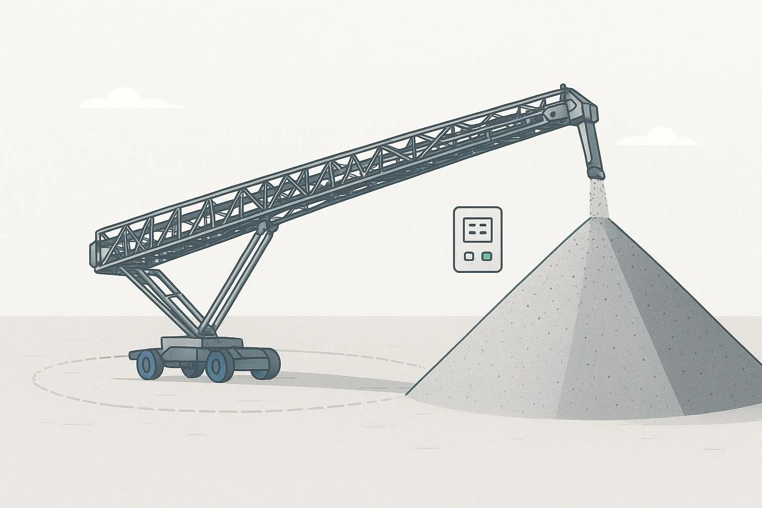
A backstop prevents reverse rotation on inclined/overland conveyors; choose type and location before you size it.
-
Low-speed head shaft mounting is preferred for lower overrunning speeds and easier inspection in most applications.
-
Base selection on worst-case reverse torque at the protected shaft, then apply the manufacturer’s service/selection factors.
-
Verify overrunning speed limits, heat management, lubrication, orientation, and sealing per the exact model manual.
-
Proof-test after installation and add the unit to your PM program; investigate any overheating, noise, or leakage immediately.
Core concepts and backstop types
Terminology and purpose:
-
Backstop = holdback = anti-runback device. It allows free rotation in the forward direction and locks in reverse.
-
Typical locations: low-speed head pulley/drive pulley shaft (common) or high-speed reducer input (space or retrofit constraints). Low-speed is generally favored to minimize overrunning RPM and heat.
Common architectures:
-
Sprag clutch: Wedge-shaped sprags engage under reverse motion; some designs have centrifugal lift-off for low drag at higher speeds.
-
Roller-ramp: Rollers climb cam ramps to lock under reverse rotation; widely used in low-speed, high-torque external backstops.
-
Ratchet/wedge: Positive locking pawls or wedges; used in specific heavy-duty or special-duty cases.
-
External low-speed backstops: Self-contained housings mounted on the head shaft with grease-purged labyrinth seals for dusty sites.
Comparison at a glance (consult OEM datasheets for exact limits):
According to Marland’s selection note, low-speed head shaft mounting with proper sizing to motor breakdown torque is standard practice for inclined conveyors. See the manufacturer’s application guidance in Size Selection for Conveyor Drive Applications (Marland, 2015) for the underlying rationale and sizing logic.
How backstops work: the engineering in plain English
During forward running, the backstop freewheels with minimal resistance. When power is cut, belt tension and the load component along the incline try to rotate the system in reverse. Think of the belt like a stretched rubber band storing energy; when the drive torque disappears, that stored energy and the inertia of the drum can try to unwind. The backstop’s internal geometry converts that reverse motion into a solid mechanical lock, holding the shaft and preventing rollback.
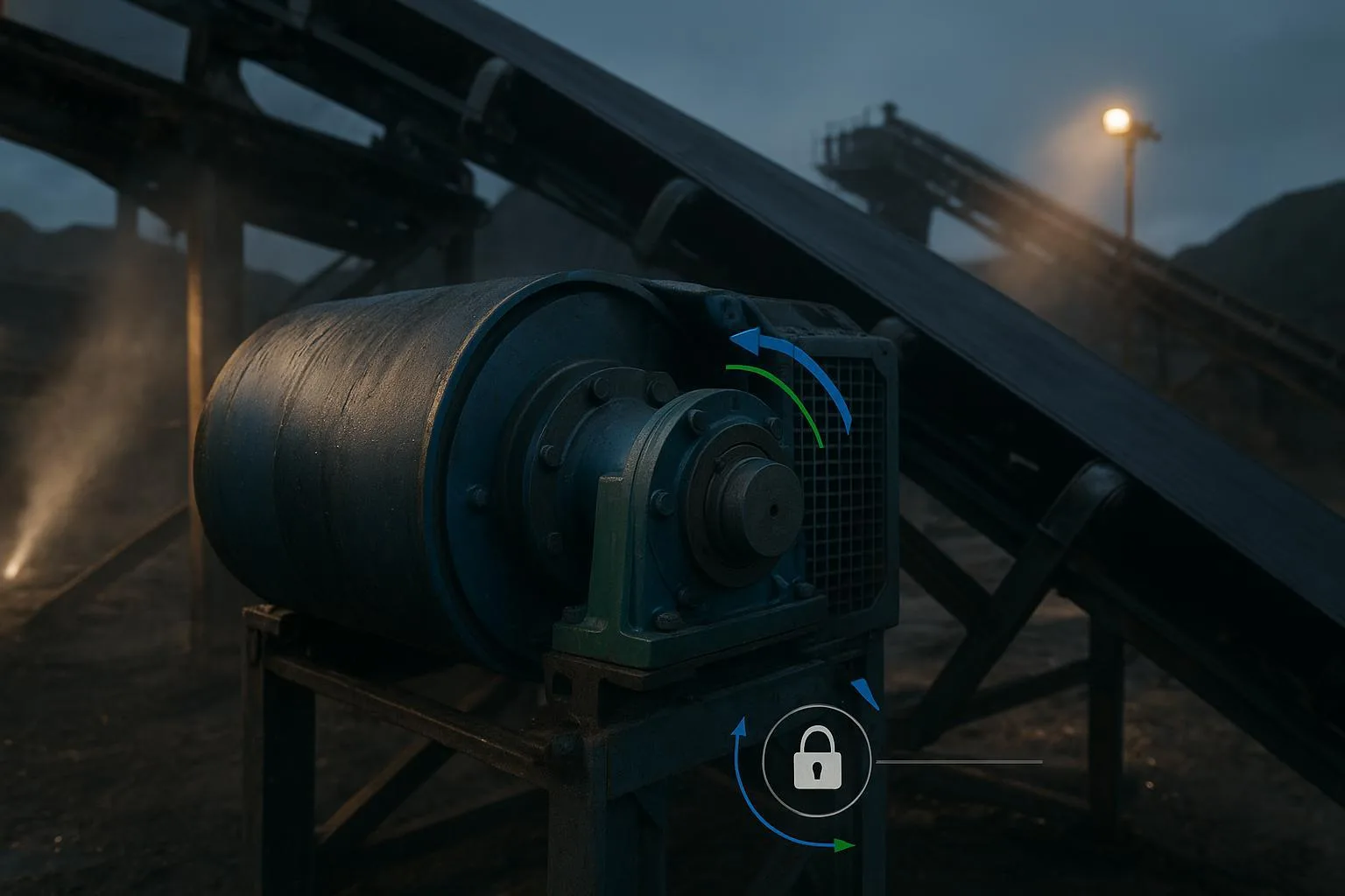
Why low-speed mounting is preferred: heat and speed. Overrunning generates heat; at high-speed input shafts, even modest drag can lead to elevated temperatures. At the head shaft, RPM is lower, heat generation is reduced, and inspection/greasing points are often more accessible. That’s why you’ll find many heavy-duty conveyors fitted with external low-speed backstops on the head shaft.
Selection workflow: How to Choose the Right Conveyor Backstop
Use this step-by-step approach to make a defensible, standards-aware choice. We’ll reference authoritative sources where helpful.
- Define the system and the protected shaft
-
Gather: incline angle θ, conveyor speed, belt and material mass per unit length, lift height, head pulley radius R, drive arrangement (single/dual), reducer ratio, and motor breakdown torque(s).
-
Decide which shaft you’re protecting (head shaft is typical). If the backstop must be on a reducer input due to layout, note that RPM will be higher and thermal checks become critical.
- Estimate worst-case reverse torque
-
Option A (drive-based): Reflect the motor(s) breakdown (stalled) torque to the protected shaft via the drive ratio and efficiency. Conservative OEM practices often base sizing on this value.
-
Option B (load-based): Approximate reverse torque from the load component along the incline: T_load ≈ W · R · sinθ, where W is the effective belt+load force at the head pulley and R is the pulley radius. Choose the larger of A or B as your base.
-
Dual or secondary drives: Marland notes that when two backstops share torque on the same shaft, each should be sized to at least 70% of the total reverse torque; primaries covering multiple motors should reflect total motor torque.
- Apply manufacturer selection factors
-
Non-TL (standard) backstops: Follow the OEM’s tables and factors, which often reflect motor breakdown torque and dynamic allowances.
-
TL-equipped backstops (temporary slipping torque): RINGSPANN explains that units with TL can use a lower selection factor (~1.2) because controlled slip reduces dynamic peaks and helps load sharing. Use the specific model’s factor.
- Check overrunning speed and heat management
-
Confirm the permissible overrunning RPM at the chosen shaft versus your conveyor’s operating speed. High-speed locations demand careful thermal review and sometimes lift-off sprag designs to reduce drag.
-
Validate lubrication method (oil bath vs grease), viscosity grade, fill volume, and temperature limits per the exact manual.
- Finalize mechanical details and environment
-
Verify direction of locking, shaft fit, key/spline details, housing orientation, and guarding provisions.
-
For dusty/wet environments, ensure labyrinth seals are grease-purged and that breather/drain features are compatible with your maintenance plan.
- Plan verification and maintenance
-
After commissioning, perform a controlled stop with load and verify no rollback per your procedures. Record temperatures, noises, and freewheeling condition for baseline.
-
Integrate the unit into PM: oil checks, seal greasing, IR temperature trending, and periodic functional checks.
Helpful references while you size and integrate:
-
Marland Clutch’s engineering note on breakdown-torque-based sizing provides practical rules of thumb and dual-unit sharing guidance. See Size Selection for Conveyor Drive Applications (2015) on the Marland site.
-
RINGSPANN’s discussion of TL backstops clarifies when lower selection factors apply and how TL improves load sharing.
-
For the reducer/backstop interface and torque reflection basics, see the BisonConvey resource Ultimate Guide to Choosing Conveyor Reducers & Gearboxes, which explains how ratios and efficiencies map motor torque to the driven shaft.
Worked sizing examples (illustrative)
These simplified examples demonstrate the workflow. Always validate against the chosen OEM’s catalog and instructions; do not substitute these for model-specific calculations.
Example A — Low-speed head shaft backstop on an inclined conveyor (dual motors)
-
Given: 1,000 t/h limestone; incline θ = 18°; belt + load effective force at head pulley W ≈ 180 kN (assumed for illustration); head pulley radius R = 0.5 m; dual 200 kW motors; motor breakdown factor = 2.0; drive efficiency η ≈ 0.95.
-
Step 1: Drive-based reverse torque at head shaft. Running torque per motor at rated conditions is roughly T_run ≈ (P/ω). With breakdown factor 2.0 and two motors, an engineering shortcut is to base selection directly on total breakdown torque reflected to the head shaft by the reducer (per OEM practice). If the reducer ratio is already accounted for at the head shaft (external backstop), use the head-shaft torque directly from motor nameplate and drive data. Conservatively, assume total breakdown torque at the head shaft T_bd_total (from both motors) is available from the drive calculation package; proceed with that value.
-
Step 2: Load-based torque: T_load = W · R · sinθ = 180,000 N · 0.5 m · sin(18°) ≈ 180,000 · 0.5 · 0.309 ≈ 27,810 N·m ≈ 27.8 kN·m.
-
Step 3: Compare and select base. In many heavy-duty cases, reflected breakdown torque governs. If your drive calc indicates T_bd_total > 27.8 kN·m, choose T_bd_total as the base.
-
Step 4: Apply selection factor. If non-TL, apply the OEM’s factor per catalog tables. If using a TL backstop and the OEM permits ~1.2 for your duty, set T_select ≈ 1.2 × base torque.
-
Step 5: Dual backstops on the same shaft? If two units share torque, size each to ≥70% of base (per Marland’s field note) unless the OEM provides a different load-sharing rule.
-
Step 6: Check overrunning RPM at the head shaft (low by design) against the catalog limit; confirm oil bath spec and seal greasing plan.
Example B — Backstop on a reducer input shaft (single motor)
-
Given: Single 250 kW motor at 1,500 rpm; reducer ratio i = 20:1; input shaft is the backstop location; motor breakdown factor = 2.0; η ≈ 0.95.
-
Step 1: Motor breakdown torque at the motor shaft: T_bd_motor ≈ (Breakdown factor × Rated torque). Rated torque T_rated = (9550 × P[kW]) / n[rpm] ≈ (9550 × 250) / 1500 ≈ 1,591 N·m. With breakdown factor 2.0, T_bd_motor ≈ 3,182 N·m.
-
Step 2: If the backstop is on the input shaft at motor speed (≈1,500 rpm), its overrunning RPM is high. Thermal performance and drag become critical; consider sprag designs with centrifugal lift-off.
-
Step 3: Apply OEM selection factors to T_bd_motor (and any transient allowances). Set T_select per catalog.
-
Step 4: Verify the permissible overrunning RPM of the selected model at ~1,500 rpm. If outside limits, relocate to a lower-speed shaft or select a model rated for that overrunning duty.
-
Step 5: Confirm oil/grease specification and guarding around the high-speed location.
In both cases, the final step is to cross-check against the chosen manufacturer’s tables and installation manual, then plan a proof-test.
Installation and lubrication best practices
-
Mounting orientation and locking direction: Double-check the freewheel direction during installation. A reverse lock in the wrong direction is a latent failure.
-
Shaft connection: Verify tolerances, key or spline engagement, and any anti-rotation torque arm details for external backstops.
-
Lubrication: Use the exact oil viscosity grade (ISO VG), fill volume, and change interval specified in the manual. External low-speed roller backstops often run oil-bath internals with grease-purged labyrinth seals for dust control.
-
Breathers and drains: Keep breathers clean; position drains to avoid pooling. Misplaced breathers cause pressure buildup and leaks.
-
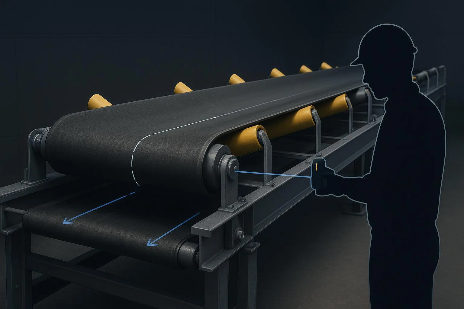
Temperature and environment: Trend housing temperature with IR gun or sensors; step in if temperatures drift upward at the same duty. For abrasive, wet, or hot environments, upgrade sealing and shielding as allowed by the OEM.
-
Safety: Guard rotating parts and implement lockout/tagout (LOTO) before servicing.
Troubleshooting and maintenance
A concise field matrix you can use during rounds. If in doubt, stop and consult the model manual or the OEM.
Proof-test checklist (align with your site procedures):
-
Commissioning with load: Perform a controlled stop and verify zero rollback over a defined dwell time.
-
Record baseline temperature, noise, and any leakage observations.
-
Verify guards and LOTO signage are in place and documented.
-
Schedule PM: oil checks, seal greasing, freewheel functional checks, and periodic torque verification as required by the OEM.
Standards, references, and further reading
-
Marland Clutch’s engineering note on backstop sizing discusses low-speed head shaft placement, motor breakdown torque basis, and dual-unit sharing: see the article Size Selection for Conveyor Drive Applications (2015) on Marland’s official site.
-
RINGSPANN explains TL (temporary slipping torque) selection and its effect on dynamic loads in The right torque in the right place (2017).
-
For installation safety context, consult OSHA’s machine guarding and Lockout/Tagout rules; they are the backbone of safe maintenance practices in the U.S.
-
CEMA’s Bulk Handling Safety Committee has documented commissioning, safe operation, and field inspection guidance for backstops; refer to meeting materials noting Guide No. 08 for scope and context.
-
ISO 5048 outlines conveyor power/tension calculations that support your torque estimates even though it is not a backstop selection standard.
Selected links for convenience:
-
According to the Marland engineering note, low-speed mounting and breakdown-torque sizing are proven practices: see Size Selection for Conveyor Drive Applications (2015) on the Marland site: https://www.marland.com/newsroom/2015/01/size-selection-for-conveyor-drive-applications
-
RINGSPANN describes TL selection factors and benefits in The right torque in the right place (2017): https://www.ringspann.com/en/news/ringspann-group/the-right-torque-in-the-right-place
-
RINGSPANN installation and operating instruction (FB/FBF) includes practical troubleshooting cues: https://static-files.ringspann.com/InstallationInstructions-FB-FBF-1015.pdf
-
OSHA’s Lockout/Tagout overview (29 CFR 1910.147) landing: https://www.osha.gov/laws-regs/regulations/standardnumber/1910/1910.147
-
CEMA meeting agenda noting the backstop field inspection guide scope (2023): https://cemanet.org/wp-content/uploads/2023/10/FEC-2023-Bulk-Handling-Safety-Committee-Meeting-Agenda-Set.pdf
-
ISO 5048 summary page: https://www.iso.org/standard/11069.html
For reducer/backstop interface fundamentals, see the BisonConvey resource Ultimate Guide to Choosing Conveyor Reducers & Gearboxes: https://bisonconvey.com/blog/ultimate-guide-choosing-conveyor-reducer-gearbox-parts/
FAQ
Q: Sprag vs roller-ramp—how should I choose? A: Match the type to shaft speed and duty. Roller-ramp backstops are common at low-speed head shafts for high torque and rugged duty. Sprag clutches (especially with centrifugal lift-off) can be advantageous at higher speeds to reduce drag and heat. Always confirm the model’s permissible overrunning RPM and lubrication.
Q: Head shaft vs reducer input—what’s the trade-off? A: Head shaft mounting reduces overrunning RPM and heat, simplifying inspection and sealing. Reducer input mounting may be necessary in tight retrofits but demands careful thermal checks and often different clutch architectures to manage drag at speed.
Q: Do I need two backstops on dual drives? A: It depends on the drive arrangement. If two units share torque on the same shaft, Marland’s field guidance suggests sizing each to at least 70% of the total reverse torque unless the OEM prescribes otherwise. In tandem primary/secondary arrangements, size per the motors contributing torque at the protected shaft.
Q: How often should I service a backstop? A: Follow the model manual for oil changes and inspections. Practically, include monthly visual checks (leaks, noise), quarterly temperature trending, and annual/freewheel functional checks, adjusting intervals for harsh environments.
Next steps
If you’re mapping a new inclined conveyor or re-rating an existing one and asking yourself How to Choose the Right Conveyor Backstop, start with the workflow in this guide: define the protected shaft, calculate worst-case reverse torque, choose location and type, apply OEM factors, then verify thermal and lubrication limits. Document a proof-test and fold the backstop into your PM program.
For system-level help integrating the backstop with your drive, pulleys, and guarding, you can consult BisonConvey for neutral, specification-first advice across belts, idlers, pulleys, and related components. Learn more at BisonConvey: https://bisonconvey.com