Importance of Backstops for Inclined Conveyors
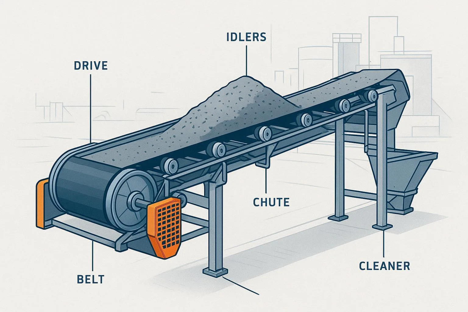
When an inclined belt conveyor stops under load, gravity wants to run it backward. A properly selected and installed backstop—also called a holdback or anti‑runback device—keeps the drive from reversing, protecting people, the structure, and the drivetrain. That is the practical essence of the Importance of Backstops for Inclined Conveyors, and it is non‑negotiable in quarries, mines, ports, steel plants, and anywhere material rides uphill.
According to industry guidance, backstops belong on most inclined conveyors to prevent rollback during stops or power loss. An application overview from West River explains the safety and asset‑protection value of backstops on hills and ridgelines in bulk handling in plain terms; see their summary in Why Backstops Are Important for Inclined Conveyors (2024) for context: inclined conveyors need anti‑runback protection to prevent gravity‑driven reverse running. More formal practice from CEMA indicates backstops as anti‑backup devices within the drive train for inclined belts, and CEMA Safety Guide No. 08 provides commissioning and inspection guidance for backstops across conveyors and bucket elevators—see CEMA’s 2019 review and Safety Guide No. 08 listing and CEMA Safety Guide 08 (store page). In North American regulation, OSHA 1926.800 explicitly requires anti‑rollback devices or brakes on inclined conveyor drives in underground construction—reinforcing the principle of preventing unintended reverse motion.
Key takeaways
-
Backstops are one‑way devices that let the drive rotate in the forward direction but lock in reverse, preventing rollback during stops or power loss.
-
The most robust placement is usually on the low‑speed side of the head/drive pulley shaft so the backstop “sees” the full reverse torque at the drum.
-
A practical sizing method is to use the motor(s) breakdown or stalled torque reflected to the low‑speed shaft, with OEM service factors and overrunning speed limits.
-
Common failure causes include undersizing, incorrect orientation, run‑out/misalignment, lubrication issues, and exceeding overrunning speed limits.
-
A disciplined PM program—oil checks, temperature/noise trending, and periodic inspections—significantly reduces risk.
Core concepts and technical explanation
A backstop is a mechanical one‑way clutch that allows free rotation in the normal running direction and locks instantly when the shaft tries to reverse. There are several mechanisms in use:
-
Sprag or roller‑ramp cam clutches are the most common for conveyors. In normal operation, the inner race overruns with minimal drag; under reverse torque, sprags or rollers wedge to transmit torque.
-
Ratchet‑and‑pawl devices appear on legacy equipment but are less common on modern inclined conveyors due to shock and wear characteristics.
-
Integrated backstops inside drum motors (e.g., motorized pulleys) lock the rotor shaft in reverse and are sealed within the pulley shell.
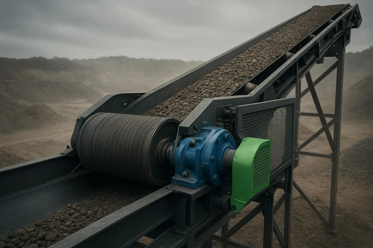
Where the backstop goes in the drivetrain matters. Application notes from Marland and others consistently recommend the low‑speed side (on the head/drive pulley shaft), intercepting reverse torque directly at the drum and minimizing intermediate component failures during a reverse event. Marland’s selection note stresses sizing to the maximum reverse torque the shaft could see—commonly the motor(s) breakdown or stall torque reflected to the low‑speed shaft—see their guidance in Marland’s size selection for conveyor drive applications and the BC model backstops summary.
Orientation and overrunning are critical. TSUBAKI’s cam‑clutch literature emphasizes verifying that the inner race overruns in the forward direction and locks in reverse; catalog pages also specify allowable overrunning speeds, which vary by model. For a representative view, see TSUBAKI’s backstop sizing guidance and a BS‑series product example. Exceeding those overrunning limits or misorienting the unit leads to heat, wear, and premature failure.
Drum motors require special attention. Rulmeca notes that mechanical backstops installed inside sealed motorized pulleys are not suitable for reversible conveyors; rotation direction (from the terminal box side) must be specified and verified, and phase sequence checked to avoid driving into the backstop. See Rulmeca’s Technical Bulletin 107 on backstops for cautionary details.
Backstop type comparison
Practical applications and use cases
-
Quarry primary incline: A 24‑inch belt lifts crushed stone from a jaw crusher to a surge bin at 12°. A short power dip during peak load tests the system. A low‑speed sprag backstop on the head pulley shaft prevents a 40–60 m uncontrolled rollback that could otherwise overload idlers and spill material. The event logs show a brief lock, no reverse travel, and normal restart after clearing.
-
Overland conveyor across rolling terrain: On a ridgeline, load variations and wind cause transient torque swings. A correctly sized backstop keeps the train anchored during coasting stops and motor trips, limiting reverse creep that could damage the structure. Industry summaries, such as the West River explainer, position anti‑runback devices as standard practice for such profiles: safety and equipment protection on inclines.
-
Wet stacker/reclaimer with drum motors: In a coastal stockyard, sealed motorized pulleys with internal backstops minimize contamination. The team verifies rotation from the terminal box side and phase sequence during commissioning, per Rulmeca’s backstop bulletin, avoiding accidental reverse drive into the backstop.
From a standards standpoint, CEMA practice treats backstops as part of the safeguarding strategy on inclines, with commissioning and inspection covered in CEMA Safety Guide No. 08. In regulated environments, preventing unintended reverse motion is mandatory; OSHA 1926.800 explicitly calls for anti‑rollback devices or brakes for inclined conveyor drives in underground construction.
Selection and implementation guidelines
The engineering goal is simple: the backstop must hold the worst‑case reverse torque with margin, avoid exceeding its overrunning speed in normal operation, and be mounted in the correct orientation with proper fits and lubrication. Practitioners often begin with motor(s) breakdown or stall torque and reflect it to the low‑speed shaft through the reducer, applying OEM service factors. Marland’s guidance is representative: size to the maximum reverse torque the shaft could see and pay attention to multi‑motor arrangements—see Marland’s selection note. TSUBAKI’s approach echoes this, with added attention to overrunning limits and direction checks; see TSUBAKI’s sizing guide.
Inputs you will need include motor power and breakdown torque, number of motors per shaft, reducer ratio and efficiency, head pulley diameter, belt speed, operating incline/load cases, and the backstop catalog’s overrunning speed limits and service factors. For lever‑arm designs (e.g., RINGSPANN FRH series), account for torque arm mounting and specified axial/radial play; a representative datasheet is RINGSPANN’s FRHN application example.
A compact selection workflow
-
Establish the worst‑case reverse torque on the shaft where the backstop will act. A conservative method is to take the motor(s) breakdown torque at the high‑speed side and reflect it to the low‑speed shaft using the reducer ratio and efficiency. For multiple drives on the same shaft, sum appropriately per OEM guidance.
-
Check the backstop’s allowable overrunning speed against the shaft speed in normal forward operation; select a model whose limit comfortably exceeds that speed.
-
Apply OEM service factors to cover shock, duty severity, and environmental conditions; select the size that meets both torque capacity and speed limit.
-
Verify mechanical details: shaft diameter and fit, keying/set‑screw provisions, torque arm geometry (if applicable), lubrication type and oil level, and sealing/breathers for the environment.
-
Confirm orientation before energizing: mark free vs. lock directions on the housing; for drum motors, verify rotation from the terminal box side and check phase sequence to avoid driving into the backstop.
Selection matrix (service factor guidance)
Installation and commissioning deserve equal attention. RINGSPANN instructions for low‑speed backstops with lever arms specify push‑fit bores on clean straight shafts, correct set‑screw torque, and torque‑arm endplay to prevent binding; see RINGSPANN’s installation instruction example. Commissioning steps are outlined in CEMA Safety Guide No. 08 (structure and intent), and Rulmeca cautions for drum motors emphasize rotation/phase checks.
Common problems and troubleshooting
Backstops rarely fail without warning. Heat, noise, and operating anomalies are your early indicators. RINGSPANN’s instructions and Marland’s application notes provide clear patterns.
Troubleshooting guide: symptom → cause → action
References: Marland’s selection note; RINGSPANN installation/troubleshooting examples; TSUBAKI orientation/sizing guidance.
Best practices and maintenance
Preventive maintenance is simple but non‑optional. Many low‑speed backstops are oil‑filled and specify automotive ATF‑type lubricants; follow the OEM list and avoid EP oils or solid additives unless explicitly approved. Initial checks are more frequent as seals settle and any residual air purges through breathers; thereafter, six‑month intervals are common for level and condition checks in moderate service. Representative OEM documents—such as RINGSPANN’s installation instructions—cover oil types, fill volumes, and inspection intervals; for an application example, see RINGSPANN’s FRHN datasheet and FRHD installation notes.
Operationally, trend bearing housing and backstop case temperature and listen for new sounds during coast‑down. Log any reverse‑event occurrences (power trips, emergency stops) with load and ambient conditions; repeated events may warrant upsizing or control changes. If you observe persistent slip under rated conditions, abnormal temperature rise, oil discoloration/metallic debris, or growing backlash, schedule a controlled stop and inspection. Replace units showing cage damage, pitting on raceways, persistent overheating, or repeated engagement anomalies. Always apply lockout/tagout and physical blocking when working on conveyors; see Martin Engineering’s procedural overview in Foundations: Lockout/Tagout procedures for safe practice structure.
Appendix: a conservative worked example
Objective: Select a backstop for a quarry head pulley where a 30 kW motor drives a 600 fpm (3.05 m/s) 24‑inch (0.61 m) belt on a 10° incline. The reducer ratio is 25:1, efficiency 94%. The motor’s breakdown torque is 2.5× its rated torque. One motor on the head shaft.
Step 1 — Motor rated torque. A 30 kW, 1500 rpm (4‑pole at 50 Hz example) motor has rated torque T_rated ≈ (9550 × kW)/rpm ≈ (9550 × 30)/1500 ≈ 191 N·m.
Step 2 — Breakdown torque at motor shaft. T_breakdown ≈ 2.5 × 191 ≈ 478 N·m.
Step 3 — Reflect to low‑speed shaft. Multiply by ratio and efficiency: T_low ≈ 478 × 25 × 0.94 ≈ 11,245 N·m.
Step 4 — Service factor. For heavy quarry duty, choose SF ≈ 2.0–2.5. Take 2.2 → Required static holding ≥ 11,245 × 2.2 ≈ 24,739 N·m (≈ 24.7 kN·m ≈ 18,240 lb‑ft).
Step 5 — Overrunning speed check. Head pulley diameter 0.61 m → circumference ≈ 1.917 m. At 3.05 m/s, pulley rpm ≈ 3.05/1.917 ≈ 1.59 rpm. Most low‑speed backstops allow far higher overrunning speeds than ~2 rpm, so overrunning is acceptable.
Result: Select a backstop with ≥ 25 kN·m holding torque and an overrunning speed rating comfortably above 2 rpm. Cross‑check shaft diameter and fit, lubrication type, and torque‑arm provisions if applicable. If a second motor is later added to the same shaft, recompute using the sum of motor breakdown torques as Marland’s guidance advises.
Notes: This example uses the breakdown torque method rather than belt tension derivations. If you prefer a belt‑tension cross‑check, estimate effective tension at the head and convert through pulley radius to compare order of magnitude.
Why the Importance of Backstops for Inclined Conveyors is non‑negotiable
The Importance of Backstops for Inclined Conveyors comes down to physics and duty: gravity, inertia, and stored energy will run a loaded belt backward if you let them. A one‑way device that locks instantly in reverse keeps personnel out of harm’s way and preserves your structure and drivetrain. In my experience, when selection follows the breakdown‑torque method with honest service factors, when overrunning limits are respected, and when orientation, fits, and lubrication are verified at commissioning, backstops rarely surprise you.
Actionable takeaways
-
Confirm whether every inclined or regenerative section has an anti‑runback device sized to the worst‑case reverse torque.
-
Verify orientation and overrunning limits during commissioning, and mark lock/free directions at the housing.
-
Add oil level/condition checks and temperature/noise trending to your PM route; escalate on persistent deviations.
-
For drum motors, lock down rotation from the terminal box side and verify phase sequence before first run.
If you are reviewing a new incline or retrofitting a legacy conveyor, and you want to ensure the drive, pulley, and idler selection align cleanly with your backstop strategy, a system view helps. As a supplier of belts, idlers, pulleys, and integrated conveying components, BisonConvey can coordinate component compatibility and share practical integration notes for heavy‑duty environments. Reach out if a custom configuration or drawing review would accelerate your decision.