Selecting a corrugated sidewall belt for steep or vertical conveying isn’t about picking a profile from a catalog; it’s about matching duty, material behavior, and geometry constraints so the system runs safely and consistently. If you work in mining, cement, ports, steel, power, chemicals, agriculture, or grain, this guide gives you a practical workflow to turn operating needs into a specification: base belt type and rating, sidewall and cleat configuration, speed, pulley diameters, transitions, bonding/splicing, and cover grades.
We’ll keep the math light but precise, and we’ll ground the checks in 2024–2025 manufacturer handbooks and technical brochures. According to the Sidewall Engineering Handbook (2024), sidewall systems rely on cross‑rigid base belts and profile geometry that respect minimum pulley diameters and transition radii; ignoring those leads to profile cracking or peeling. See the methodology in the Sidewall Engineering Handbook (2024) and cleat/pulley cautions in Continental Belting’s 2024 sidewall brochure.
Preparation checklist for sidewall conveyor belt selection
Before any calculations, capture the core data. Think of this as your one‑page brief for sidewall conveyor belt selection.
| Category | Data to collect |
|---|---|
| Duty | Capacity (t/h), lift height (m), conveying angle (°), center distance (m), loading conditions |
| Material | Bulk density (t/m³), max lump size S (mm), abrasiveness, moisture, temperature (°C), oil/flame properties, tendency to roll or stick |
| Geometry | Available pulley diameters, available transition lengths, head chute layout, idler configuration |
| Constraints | Max belt speed, drive power limits, environmental constraints (dust, corrosion), maintenance preferences |
Step-by-step workflow
- Define duty: capacity, lift, conveying angle, center distance, and loading conditions.
- Record material properties: bulk density, max lump size S, abrasiveness, moisture, temperature, special properties (oil, flame), and flow behavior.
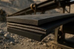
- Choose the cross‑rigid base belt and rating: textile cross‑rigid (EP/NN with rigid plies or steel inserts) vs cross‑rigid steel‑cord. Use rating ranges informed by the handbook and company profiles. See guidance in the Sidewall Engineering Handbook (2024).
- Configure sidewalls and cleats: pick cleat family (T, C, TC, TCW), height, and pitch; sidewall height/class; ensure pocket geometry suits lump size and angle. Continental’s tables list dimensions and minimum pulley diameters for each series; see Continental Belting (2024).
- Set belt speed and estimate capacity using a pocket‑based formula:
Q = 3.6 × Ap × v × ρ × kf. - Verify pulley diameters and transitions: respect base‑belt minimums and cleat D1/D2 minima; validate transition lengths/radii per the handbook.
- Specify bonding/splicing and cover grades: hot‑vulcanized profiles; splice type per carcass; select cover compounds against ISO/DIN/ASTM tests.
- Draft the vendor RFQ using the template and define acceptance tests.
Engineering checks, formulas, and typical ranges
Sidewall conveyor belt selection hinges on pocket geometry, speed, and stiffness constraints. Here are the essentials engineers actually use.
-
Capacity (t/h):
Q = 3.6 × Ap × v × ρ × kfWhere Ap is effective pocket area (m²), v is belt speed (m/s), ρ is bulk density (t/m³), kf is pocket fill factor (dimensionless). The 3.6 converts m³/s to t/h, matching industry practice in the Sidewall Engineering Handbook (2024).
-
Fill factor (kf): Use 0.6–0.7 as a conservative starting point. Free‑flowing fines support higher kf; coarse lumpy material needs lower values. Verify with OEM charts.
-
Belt speed: Many steep/vertical systems run about 1.0–3.0 m/s. Slower speeds improve pocket filling for coarse, abrasive, or fragile material. Speed affects impact on cleats at loading and discharge.
-
Pocket width vs lump size: A simple working rule is effective pocket width ≥ 2× maximum lump size S to avoid interference and spillage. Confirm geometry against cleat/sidewall series tables (T/C/TC/TCW) in Continental Belting (2024).
-
Base belt and rating: Cross‑rigid textile belts suit moderate tension ranges (roughly ≤ 1000–1600 N/mm) where some longitudinal stretch is acceptable; cross‑rigid steel‑cord suits very high elevation/low elongation needs with ratings in the 1000–2500 N/mm range. Select based on calculated working tension and supplier safety factors; ranges synthesized from Sidewall’s 2024 handbook and profile.
-
Pulley diameters and transitions: Always check both base‑belt minimums and cleat D1/D2 minima, and use the larger as your requirement. Continental explicitly cautions that “Diameters D1 and D2 of the cleats must be observed.” Transitions from horizontal to steep/vertical must meet minimum lengths and equivalent bending radii per the handbook.
Why all the fuss on D1/D2 and transitions? Picture trying to bend a stiff pocket around a small drum—the sidewall fold and cleat base are stressed, and repeated cycling leads to cracks or peel. Respecting minima keeps fatigue within manageable limits.
Worked micro-examples
These neutral examples show how inputs cascade into sidewall conveyor belt selection. Numbers are illustrative; always verify with vendor tables.
Ore, 300 t/h at 85°
- Duty: 300 t/h, vertical lift 50 m, conveying angle 85°, center distance 70 m.
- Material: ρ ≈ 1.8 t/m³, max lump size S = 100 mm, abrasive.
- Geometry: Head/tail pulleys available at 800/630 mm; transitions can accommodate 6 m.
Choice path:
- Base belt: Working tension indicates high duty with low elongation requirement; shortlist cross‑rigid steel‑cord around 1250–1600 N/mm (per Sidewall tables).
- Pocket geometry: Target effective pocket width ≥ 2×S → ≥ 200 mm; choose TC cleats around H ≈ 120–160 mm; pitch 300–400 mm after checking series minima in Continental Belting (2024).
- Speed and capacity: Use kf = 0.65 for abrasive ore; pick v ≈ 1.5–2.0 m/s to balance filling and impact. Compute Ap from the series table (reduced by allowances); iterate v and pitch until
Q≈ 300 t/h. - Pulleys/transitions: Confirm base‑belt minimums at chosen rating; verify cleat D1/D2 for selected height; if D1 cleat minimum exceeds 800 mm, upsize or change cleat series; validate transition radius per the Sidewall Engineering Handbook (2024).
- Bonding/splicing: Specify hot‑vulcanized profiles; steel‑cord splice per manufacturer template; define QA coupon peel/pull tests.
Grain, 50 t/h at 80°
- Duty: 50 t/h, vertical lift 25 m, angle 80°, center distance 35 m.
- Material: ρ ≈ 0.75 t/m³, max lump size S = 12 mm, free‑flowing.
- Geometry: Pulleys available at 500/400 mm; transitions ≈ 4 m.
Choice path:
- Base belt: Cross‑rigid textile (EP) rating ≈ 500–800 N/mm sufficient; easier installation and acceptable elongation.
- Pocket geometry: T or C cleats at H ≈ 80–120 mm; pitch 200–300 mm; pocket width easily meets ≥ 2×S.
- Speed and capacity: Use kf ≈ 0.8 for free‑flowing grain; v ≈ 2.0–2.5 m/s is feasible; compute Ap from series; tune pitch for
Q≈ 50 t/h. - Pulleys/transitions: Confirm base‑belt minimums and cleat D1/D2 at selected height; transitions at 4 m may be adequate but verify radii.
- Bonding/splicing: Hot‑vulcanized profiles; fabric finger splice; define inspection after trial run.
Practical example (neutral brand reference)
Disclosure: BisonConvey is our product. In practice, an engineer may request a proposal for “ore 300 t/h at 85°, S = 100 mm, target v = 1.8 m/s, cross‑rigid steel‑cord ~1600 N/mm, TC cleat H = 140 mm, pitch 350 mm, D1/D2 per series.” A vendor response should include base‑belt rating, cleat/sidewall series, verified D1/D2 minima, transition length/radius recommendations, and bonding/splice procedures with acceptance tests. The structure—not the brand—matters; it’s a replicable way to brief any supplier.
Bonding, splicing, and QA
Hot‑vulcanized sidewalls and cleats are the de facto standard for steep/vertical service because matched rubber systems and controlled cure cycles deliver high peel strength and fatigue resistance, as documented in the Sidewall Engineering Handbook (2024). Cold‑bonded profiles suit repairs or light duty but are more sensitive to contamination and thermal cycling.
- Fabric belt splices: Stepped or finger splices (hot‑vulcanized) with bias‑cut ends; interrupt profile attachments at the splice and re‑vulcanize after.
- Steel‑cord belt splices: Multi‑step or finger splices per the supplier’s template; strict cord positioning and QA. Avoid mechanical fasteners except emergency use in high‑lift service.
- QA acceptance: Calibrated press parameters, documented procedures, coupon peel/pull tests, and early‑life inspections. For standards context on abrasion resistance and flame/oil grades, see Dunlop’s ISO 4649 explainer (2025) and a technical overview referencing ISO 340 and ISO 1817.
Troubleshooting matrix
| Symptom | Probable cause | Corrective action |
|---|---|---|
| Profile peeling at transitions | Transition length/radius below minima; excessive bending vs D1/D2 | Increase transition length/radius; upsize pulleys; verify cleat series minima per handbook and brochure |
| Spillage/rollback in pockets | Pocket width < 2× S; cleat height/pitch not suited; speed too high | Increase pocket width or cleat height; reduce speed; adjust pitch; confirm fill factor against OEM charts |
| Cleat damage at loading | Over‑speeding with coarse lumps; impact angle unfavorable | Reduce speed; add impact idlers/chute redesign; choose reinforced cleats (TCW) |
| Tracking issues on return run | Insufficient transverse rigidity; poor idler alignment | Use cross‑rigid base belt; correct idler alignment; add tracking aids |
| Premature splice fatigue | Wrong splice geometry; inadequate QA cure | Follow supplier splice template; re‑vulcanize profiles after splicing; implement coupon tests |
Vendor RFQ template
Use this table to request comparable proposals and speed up sidewall conveyor belt selection.
| Field | Your inputs |
|---|---|
| Capacity and angle | t/h and conveying angle (°) |
| Lift and center distance | Vertical lift (m); center distance (m) |
| Material properties | ρ (t/m³), max lump size S (mm), abrasiveness, moisture, temperature, oil/flame |
| Base belt preference | Cross‑rigid textile or steel‑cord; target rating (N/mm) if known |
| Sidewall/cleat | Sidewall height/class; cleat family (T/C/TC/TCW), target height (mm), pitch (mm) |
| Speed | Target belt speed (m/s) or allowed range |
| Pulleys/transitions | Available pulley diameters; available transition length; idler layout |
| Covers | Abrasion/flame/oil/heat grade targets; cite ISO 4649/ISO 340/ISO 1817 as applicable |
| Bonding/splicing | Hot‑vulcanized profiles; splice type per carcass; acceptance tests (peel/pull) |
| Acceptance tests and KPIs | Trial run duration; max spillage %, visual inspection criteria |
Safety notes and installation tips
- Respect minimum pulley diameters for both the base belt and cleat series. If the cleat’s D1/D2 requirement is larger than the base‑belt minimum, the larger value governs. A small drum can be a big problem.
- Validate transition lengths and equivalent bending radii before fabrication. Shortening a transition after install is costly—and risky.
- Define QA upfront: hot‑vulcanization parameters, splice geometry, coupon tests, and early inspections. What would you rather discover—an adhesion issue in a test coupon or after a 72‑hour trial run?
For additional design context specific to North American layouts, see the selector tables and cautions in Bi‑State Rubber’s Rev. 08/2024 sidewall guide.
Next steps
Ready to brief vendors and compare proposals? Use the RFQ template above and ask each supplier to confirm pocket area Ap, fill factor kf, D1/D2 minima, and transition radius assumptions in writing. If you need a neutral sanity check on a steep conveying spec, contact a sidewall specialist. If you prefer a turnkey package, BisonConvey can review your inputs and provide a proposal aligned to the checks in this guide—neutral, testable, and cited to the published 2024–2025 references.
Author: Conveyor systems engineer with hands‑on experience specifying steep‑incline sidewall systems in mining, cement, ports, and grain.