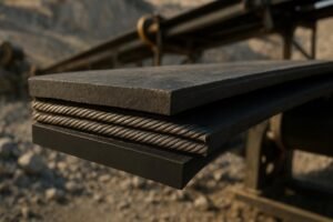
If you’re evaluating rollers for a troughed belt conveyor, a structured conveyor roller comparison beats guesswork every time. This guide shows a repeatable way to compare designs by type and material, tie them to duty class and standards, and verify the choice on site—without relying on promotional claims.
What a Good Conveyor Roller Comparison Looks Like
A sound comparison does three things:
- Maps your application to a standards-based duty class and geometry.
- Selects idler types and materials that fit load, environment, and maintenance realities.
- Verifies spacing, diameters, seals, and alignment so the belt runs quiet, efficient, and safe.
Use the standards as your anchor. ANSI/CEMA Standard No. 502 defines dimensional and selection guidance for troughing and return idlers across classes B through F, with the 2022 edition consolidating selection content and tolerances. See the edition summary in the CEMA store for scope and terminology in plain language: CEMA Standard 502 overview (2022).
Conveyor Roller Comparison Workflow
A practical conveyor roller comparison follows the same sequence designers and reliability engineers use. Think of it as measure → classify → select → verify.
Capture the conveyor and material data
Start with hard numbers and observations:
- Belt width and speed
- Capacity (TPH) and bulk density
- Lump size and drop height at loading
- Ambient and process conditions: dust, moisture, corrosives, washdown, temperature
- Existing problems to solve: belt wander, carryback, noise, impact damage
These inputs feed every downstream decision. For a quick refresher on the core variables and how manufacturers apply them, see the concise tables in the PPI Idler Selection Guide.
Map duty class to CEMA ranges
Duty class (B, C, D, E, F) reflects expected loads, belt width, roll diameter, and frame strength. You don’t need to reproduce gated tables to make a call: use the manufacturer’s classed offerings as a proxy, aligning your width, speed, and load. If you’re consistently near a class boundary or you’re upgrading capacity, err toward the heavier class to absorb growth and abuse.
Select the idler type by location
- Carrying or troughing sets support the loaded belt; three-roll 20°, 35°, or 45° sets are common.
- Impact idlers live under the loading chute to absorb shock and protect the belt.
- Return idlers support the empty belt; rubber disc or spiral options can shed sticky fines.
- Training or self-aligning idlers help correct belt wander at intervals along the run.
For a quick overview of roles and layouts, the Benetech and Rulmeca primers are handy. For placement of self-centering sets, install them beyond pulley influence and at intervals; Rulmeca recommends away from pulleys and then in regular spacing along the line—see Rulmeca self-centering sets guidance.
Choose the troughing angle
Trough angle affects capacity and belt stress. Steeper angles (35° and 45°) increase carrying area, useful for higher throughput or materials with higher surcharge angles. But steeper troughs demand greater transition distances from flat to trough to avoid overstressing the belt. Martin Engineering’s reference on transition distance is a clear explainer: belt transition distance fundamentals.
Pick shell materials and lagging
Steel shells are the baseline in many plants, but polymers have compelling use cases:
- HDPE shells cut weight and resist corrosion in wet or caustic areas.
- UHMWPE brings superior sliding abrasion resistance and very low friction for sticky or abrasive fines.
- Rubber or ceramic lagging on impact rolls cushions shocks and improves grip where the belt takes abuse.
For material properties that matter in practice (density, friction, abrasion), the polymer science is well documented. Celanese’s UHMWPE guide summarizes low friction and high sliding abrasion resistance in one place: Celanese UHMWPE polymer guide.
Specify bearings and seals
Bearings fail early when contamination defeats the seals. Look for sealed-for-life ball bearings with layered sealing: a contact seal at the front line plus a grease-filled labyrinth behind it. This combination keeps ingress low without adding excessive drag. ASGCO’s CEMA idlers brochure illustrates triple-labyrinth concepts used widely across the industry: ASGCO CEMA Idlers sealing overview.
Confirm diameters and spacing
Diameter and spacing influence sag, vibration, noise, and energy. As a starting point (verify against your loads and belt stiffness):
- Carrying idlers at roughly 1.2 m (about 4 ft)
- Impact idlers in loading zones at 0.3–0.6 m (1–2 ft)
- Return idlers at 2.4–3.0 m (8–10 ft)
Common roll diameters progress with duty and speed: 4 and 5 inches are typical, with 6 inches and up for higher loads and faster belts. PPI’s guide provides context for spacing and diameter norms relative to belt width and application: PPI Idler Selection Guide.
Plan inspections and alignment
Even the right roller fails early if alignment and housekeeping slide. Keep pulleys and idlers square and level, install self-aligning sets away from pulleys, and schedule routine visual checks plus periodic spin/noise checks. If the belt is wandering, install training troughers at intervals—PPI’s ProTrainer guidance cites on the order of 100–150 ft spacings; Rulmeca and others advise placing the first unit well clear of pulleys.
Idler Material Comparison Matrix
Below is a quick matrix to inform material choices during conveyor roller comparison. Values are qualitative and must be validated against specific product data sheets and your environment.
| Property | Steel shell | HDPE shell | UHMWPE shell | Rubber-lagged impact shell | Ceramic-lagged impact shell |
|---|---|---|---|---|---|
| Abrasion resistance (sliding) | Good; can groove in fines | Fair–good | Excellent; very low wear in sliding contact | Good; rubber absorbs abrasion | Excellent in high-abrasion impact zones |
| Impact tolerance | High structural strength | Good; resilient | Very good; high impact energy absorption | Excellent for shock at loading | Excellent; hard surface with robust bonding |
| Corrosion resistance | Needs coating/stainless | Excellent | Excellent | Depends on core; rubber resists many media | Depends on core; tiles inert, grout quality matters |
| Temperature range | Very wide; high-temp capable | Moderate; check spec | Moderate; typically up to ~80–85°C, very good at low temps | Rubber heat limits apply | Ceramic heat tolerant; check adhesive system |
| Weight | Heavy | Light | Light | Heavier than polymer shells | Heavier than polymer shells |
| Noise | Can be higher if worn | Lower due to damping | Lower; self-lubricating surface | Moderate; rubber damping | Moderate |
| Contamination risk | Rust scale possible | None from shell | None from shell | Rubber shed possible | Tile chipping if abused |
| Cost index | Baseline | Often higher than steel | Often higher than HDPE | Premium in impact zones | Premium in severe impact zones |
Sources for properties include the Celanese UHMWPE guide for friction and abrasion behavior as well as manufacturer catalogs referenced elsewhere.
Worked Example for a Medium-Duty Conveyor
Scenario: A 36-inch belt moves 400 TPH of crushed aggregate (bulk density 1.6 t/m³) at 3.5 m/s. The loading chute drops material 0.6 m. Environment is dusty with periodic washdown.
-
Data capture You’ve documented width, speed, capacity, drop height, and environment. No chronic tracking issues, but the loading zone shows belt cover scuffing.
-
Duty class Using manufacturer tables tied to CEMA 502 conventions, a 36-inch belt at this load and speed often lands in CEMA D for carrying sets to provide headroom for impact and occasional overloads. If components upstream are aging or capacity is expected to grow, stay with D rather than C.
-
Idler types and trough angle
- Carrying: three-roll troughers at 35° for a good balance of capacity and containment.
- Impact: rubber-ring impact idlers under the loading chute.
- Return: rubber disc returns to discourage fines buildup.
- Training: self-aligning troughing idlers installed beyond pulleys at intervals.
- Materials and lagging
- Carrying shells: steel or UHMWPE. If corrosion and noise are concerns, UHMWPE helps; if elevated temperatures appear downstream, steel is safer.
- Impact zone: rubber-lagged impact rolls to cushion the 0.6 m drop.
- Returns: steel or polymer returns depending on corrosion exposure.
-
Bearings and seals Select sealed-for-life deep-groove ball bearings with a contact front seal and triple-labyrinth secondary seal. This arrangement keeps dust and washdown water out while keeping drag modest.
-
Diameter and spacing
- Carrying: 5-inch rolls at 1.2 m spacing are a solid starting point.
- Impact: 5- or 6-inch impact rolls at 0.45 m spacing through the loading zone, then transition back to carrying spacing.
- Return: 5-inch returns at 2.7 m spacing.
- Verification checks
- Confirm transition distances into and out of the 35° trough meet belt manufacturer guidance to avoid edge tension spikes. Martin Engineering’s note on transitions is a helpful cross-check.
- Spin test a few rollers after installation: they should rotate freely and quietly; any gritty feel or short free-spin suggests contamination or seal damage during install.
- Track belt wander over a week of service; if drift persists, move or add a self-aligning trougher further from pulleys per supplier spacing guidance.
Result: You’ve chosen a CEMA D set with 35° trough, impact protection in the loading zone, seals appropriate for dust and washdown, and spacing aligned with norms. Energy draw should remain reasonable with 5-inch rolls and layered seals; if power is tight, consider larger diameters or low-rolling-resistance designs verified by the supplier.
Energy, Seals, and Reliability Considerations
Energy For long conveyors, indentation rolling resistance dominates. Larger roll diameters can reduce rolling resistance; in one documented overland project, designers used large-diameter rolls and reduced idler counts to save drive power and capital. See the CEMA conference paper on the Curragh CV1103 system for design logic and outcomes: overland conveyor design case study.
Seals and bearing life Layered sealing (contact plus labyrinth) is a proven way to extend bearing life in dusty and wet service. It reduces ingress without adding the high drag seen in some heavy-contact designs. The ASGCO CEMA Idlers sealing overview depicts arrangements used broadly in industry.
Placement and tracking Self-aligning/training idlers are most effective when placed away from pulleys and then at intervals along the conveyor. Rulmeca’s guidance provides a simple rule of thumb for these positions: self-centering sets guidance. Transition distance from flat to trough should be sized to protect the belt, as explained in Martin Engineering’s transition distance fundamentals.
Verification, Maintenance, and Quick Troubleshooting
A disciplined verification process keeps good selections performing well.
- Routine visual inspection: look for seized rolls, uneven wear, material buildup, and skewed frames.
- Functional checks: hand-spin suspect rolls, listen for roughness, and note any heat at bearing housings after running.
- Alignment: measure belt edge offset at three points per span; adjust frames or training idlers where drift is consistent.
Troubleshooting snapshot
| Symptom | Likely cause | Diagnostic action | Corrective action |
|---|---|---|---|
| Belt edge wear on one side | Misaligned frames or pulleys | Measure edge offset along a span | Square frames; add/move training idlers |
| Loud or “gritty” roller | Bearing contamination or failure | Hand spin and stethoscope check | Replace roller; review sealing and housekeeping |
| Cover damage at loading zone | Excess drop or hard impact | Check drop height and chute alignment | Install impact idlers; reduce drop; adjust chute |
| Material buildup on returns | Sticky fines carryback | Inspect belt cleaning and moisture | Improve cleaners; use disc or spiral returns |
Log findings and track mean time between replacements. Over one or two quarters, the data will tell you whether polymer shells, different seals, or spacing changes are paying off.
Neutral Example Using a Vendor Workflow
Disclosure: BisonConvey is our product. In practice, you can map your selections to a vendor’s catalog to verify availability across classes and materials. For example, BisonConvey offers carrying, impact, return, and training idlers across CEMA classes with steel and polymer shell options; you can line up your chosen class, roll diameter, spacing, and seal configuration against their spec sheets to confirm a compatible bill of materials. Keep the choice grounded in the workflow and sources above rather than brand claims.
Closeout and next steps
A rigorous conveyor roller comparison isn’t complicated—it’s consistent. Capture the operating data, tie it to a CEMA-aligned duty class, select types and materials by location and environment, then verify diameters, spacing, seals, and placement. Document what you installed, monitor KPIs like downtime and energy draw, and adjust. The result is steadier tracking, less wear, and a conveyor that stays in service when you need it most.
References
- CEMA 502 overview for idler dimensions and selection scope: ANSI/CEMA Standard No. 502-2022
- Selection variables and spacing context: PPI Idler Selection Guide
- Polymer properties affecting friction and abrasion: Celanese UHMWPE polymer guide
- Self-aligning idler placement guidance: Rulmeca self-centering sets
- Sealing arrangements for dusty/wet duty: ASGCO CEMA Idlers sealing overview
- Transition distance explainer: Martin Engineering on belt transition distance
- Overland energy design case study: Curragh CV1103 overland conveyor design paper