Selecting the right conveyor rollers (idlers) on an overland system isn’t just about “what fits.” On multi-kilometer runs, idler choices influence energy consumption, uptime, belt life, and maintenance safety. The goal is simple: a stable belt profile with controlled sag, clean tracking, sealed-for-life bearings, and minimized motion resistance—delivered at a life-cycle cost that stands up to years of dust, weather, and load variation.
What you need to know up front
Before you pick diameters or shell materials, establish the conveyor’s context:
- Belt type and width: steel cord vs. fabric; final width drives idler geometry and load distribution.
- Speed and material profile: steady state vs. variable; bulk density, lump size, and abrasiveness.
- Duty and terrain: long, level run or undulating; trestle spans; wind exposure.
- Environment: temperature, moisture, dust level, corrosion (coastal/chemical), and cleaning strategy.
- Reliability goals: inspection access, mean time between failures (bearings/seals), spare strategy, and safety requirements.
Standards set the baseline. Idler dimensions, tolerances, and selection context are defined in CEMA classes B–G; the latest edition also summarizes selection examples. See the official listing for CEMA Standard No. 502–2022: CEMA’s “Bulk Material Belt Conveyor Troughing and Return Idlers” (2022).
Step-by-step selection workflow
Step 1 — Define duty and environment
Document belt width, speed, design capacity, material characteristics (bulk density, max lump, abrasiveness), loading conditions, and ambient environment. Note special zones: loading/impact, transitions, convex/concave curves, and areas with carryback risk. This grounding drives every later choice.
Step 2 — Set belt sag target and preliminary idler spacing
For long-distance conveyors, a practical target is about 1–2% vertical sag between carry idlers; too much sag raises indentation rolling resistance (IRR) and risks spillage, too little can imply excessive tension or idler count. A commonly cited field reference states: “Proper belt tension must result in 1%–2% deflection between idlers.” See the field example in the Belt-Way Conveyor Belt Scale Product Manual (2021).
Calculate an initial carry and return spacing to achieve that sag under design load, then iterate after you choose trough angle and diameter. Remember: tighter spacing lowers sag but increases idler count and bearing/seal friction; wider spacing reduces count but raises belt deflection and IRR. The optimal point balances both.
Step 3 — Choose trough angle and verify transition design
Typical working angles are 20°, 30°, 35°, and 45°. Steeper angles (35°–45°) increase cross-sectional area and containment for finer or more fluid materials; shallower angles suit coarse, stable lumps and help with transitions.
For transitions from a flat pulley to a troughed belt, follow DIN-based practices to protect the belt edges. A two-stage transition—tail pulley to ~20° wings, then ramp to the final angle through the load zone—reduces edge stress and spillage. Maintain a sensible free edge distance (commonly about 115 mm minimum, increasing with expected wander), and verify transition length against belt stiffness. A concise overview referencing DIN 22101 is summarized by North American Mining: “Understanding idler trough angle in transition zone belt loading” (2023).
Step 4 — Select roller diameter
Larger diameters reduce rotational speed and contact pressure, typically lowering rolling resistance and bearing load. On heavy-duty overland conveyors, you’ll commonly see carry roll diameters in the 5–7 inch (≈127–178 mm) range, scaling with belt width and load; verify load and rpm limits against vendor data. For heavy-duty class context, vendors’ CEMA E-class pages provide useful ranges; exact tables vary by manufacturer, so use the vendor’s engineering catalog and your calculations.
Trade-offs here are straightforward: bigger rolls reduce rpm and deformation but add mass and cost; smaller rolls weigh less and cost less but spin faster and may wear sooner. Confirm shaft diameter, shell thickness, and bearing selection meet the combination of load, speed, and environmental exposure.
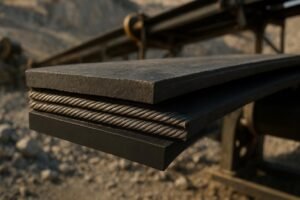
Step 5 — Choose shell material
Select materials based on impact duty, corrosion potential, noise/energy priorities, and maintenance strategy. A balanced, field-proven approach is to use robust steel on carry side—especially in impact zones—and consider polymer/UHMWPE on return runs or in corrosive areas. Stainless options are valuable for aggressive chemical or coastal exposure.
| Shell material | Key properties | Typical use cases |
|---|---|---|
| Steel | High impact tolerance; wide temperature range; readily available; heavier rotating mass | Carry side in heavy loading/impact areas; abrasive service; high-temperature environments |
| Polymer/UHMWPE/HDPE | Lighter (often roughly ~50% of steel mass), corrosion-resistant, quieter; reduces rotating mass | Return runs; coastal/corrosive environments; noise-sensitive sites; some heavy-duty variants for carry side per vendor data |
| Stainless (shell/parts) | Corrosion resistance; hygienic surfaces; higher cost | Coastal, chemical, fertilizer plants; where corrosion is the life-limiting factor |
For an illustration of hermetic sealing and heavy-duty steel rollers (non-endorsement), see a vendor technical overview: Rulmeca “Steel rollers — PSV”.
Practical worked example (neutral)
Disclosure: BisonConvey is our product.
Scenario: 1,200 mm steel-cord belt, 4.5 m/s, fine limestone, overland trestle with moderate wind, coastal humidity. Objectives: stable tracking, low energy, minimal bearing failures, and safe maintenance access.
- Steps 1–2: Set a 1–2% sag target; preliminary carry spacing calculated to meet sag at design load; return spacing slightly wider after confirming cleanliness strategy (scrapers + V-return idlers).
- Step 3: Choose 35° troughing for capacity/containment; implement a two-stage transition from tail to ~20° then to 35° by the end of loading, with verified free edge distance and skirt length per DIN-based practice.
- Step 4: Select a larger carry roll diameter (e.g., in the 5–7 inch class) within bearing rpm limits; confirm shaft diameter and shell thickness for expected lump impacts.
- Step 5: Specify steel carry rollers in the load zone; polymer/UHMWPE return rollers for corrosion resistance and lower rotating mass along long trestle spans. A manufacturer like BisonConvey can be used to compile a neutral spec sheet with belt width, roll diameter, class, spacing, and sealing notes; finalize using your calculations and standards references.
This workflow keeps claims conservative and calculations central. The final spec is validated against CEMA/DIN guidance and your power/tension model.
Step 6 — Specify bearings and sealing
Bearing and seal integrity is the top life-limiter on long conveyors. Look for multi-stage labyrinths paired with inner contact/lip seals to block dust or slurry with low friction; choose permanently lubricated, sealed or shielded bearings sized for speed and load with interference-fit shafts; and prioritize low total indicated runout (TIR) shells with concentric end-caps to reduce vibration and tracking noise. A practical reference showing hermetic sealing concepts for long-life duty is this vendor overview: Rulmeca “Steel rollers — PSV”.
Step 7 — Validate energy (IRR) and recalc power
On long, level runs, indentation rolling resistance—belt rubber hysteresis over idlers—often dominates motion resistance. You can lower IRR by selecting larger diameters (within your structural and capital constraints), optimizing spacing to keep sag near target, and considering low rolling resistance (LRR) belt compounds. For a concise explanation of energy-saving mechanisms and the f-value concept, see this overview: ConveyorBeltGuide “Energy saving”. Finalize spacing and diameter with a power/tension model; software such as Overland Conveyor’s Belt Analyst helps iterate idler pitch, diameter, and belt compound for a stable, efficient design.
Step 8 — Plan maintenance, inspection, and safety
Define inspection intervals suitable for the route length and access constraints. Train crews to spot early bearing failures (localized heat, tonal noise, uneven shell wear, grease purge or dust caking near seals) and to correct tracking issues before they damage belt edges. On elevated trestles, plan safe access platforms and retrieval methods for roll changeout. Guard moving parts and enforce LOTO before servicing idlers. OSHA’s general machine guarding provisions apply to pinch points on conveyors; see an example of conveyor belt enclosures under machine guarding guidance: OSHA eTools – Conveyor belt enclosure example.
Common pitfalls and quick checks
- Transition troubles: Spillage and edge wear near the tail often trace back to inadequate transition length or skipping a two-stage approach. Re-check DIN-based transition calculations and free edge distance.
- Over-tight or over-loose spacing: If you’re replacing rolls too often, listen for bearing noise spikes—then revisit spacing and sealing. Excess sag shows up as material instability and power draw creep.
- One-size-fits-all materials: Steel in every position isn’t always optimal. Return runs in corrosive corridors may live longer and run quieter with polymer shells; confirm with your vendor’s load limits.
Next steps
Confirm your duty context and set a sag target near 1–2%. Select a trough angle, then verify transitions and free edge distance. Choose diameter and shell material, specify bearings and seals, and model the energy implications to fine-tune spacing and power. For authoritative details and examples, consult CEMA Standard No. 502–2022 for idler classes and tolerances, the DIN-based summary in North American Mining’s transition article (2023) for transition logic, and run a power/tension model with Belt Analyst. If you want a second set of eyes, involve your engineering team or a qualified supplier to review the draft spec, bearing and sealing architecture, and access provisions before procurement.