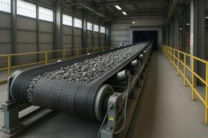
Conveyors run for long hours, move heavy loads, and rarely get the spotlight in energy programs—yet they’re often a Significant Energy Use under ISO 50001. If you meter a few lines for a week and normalize by throughput, you’ll usually find practical savings hiding in plain sight: better speed control, smarter motor/gearbox choices, and lower friction add up to meaningful kWh cuts without compromising throughput or safety. According to the U.S. DOE’s guidance on energy management systems, ISO 50001 provides a structure to baseline, improve, and verify performance with clear EnPIs like kWh per ton conveyed; see the DOE ISO 50001 eGuide overview.
Where conveyor energy really goes
Think of a conveyor’s losses in three buckets: belt indentation rolling resistance, idler rotation/friction, and drivetrain (motor/gearbox) efficiency. Engineering analyses show indentation rolling resistance often dominates in long, horizontal belt conveyors—reported near ~61% of total resistance in a 1 km case—while idler rotation sits closer to ~6%. That’s why belt compound, idler design, and speed matter so much. See the technical breakdown in “Improved energy efficiency in troughed belt conveyors” (engineering paper).
Oversizing is another silent energy drain. When motors and reducers are spec’d far above actual load, part‑load efficiency suffers and parasitic losses increase. Right‑sizing with CEMA power calculations and verified efficiency curves avoids this trap.
Five proven levers—and how to implement them
1) Variable speed drives (VFD/VSD) with speed control
- What works: Tie belt speed to material flow. During low‑throughput periods, reduce speed with conservative ramp rates; restore speed when demand rises. Peer‑reviewed conveyor studies show typical savings around ~9–18% when speed tracks flow, with a prudent planning range of ~5–25% depending on duty cycle and control quality; see Ji et al. (2020) PLOS ONE.
- How to implement: Submeter kWh and log throughput (tons/hour) and setpoints for a representative baseline. Integrate sensors (load cells or optical) and PLC/SCADA logic. Sequence start/stop and interlocks to avoid idle running.
- Spec notes: In the EU, ensure drives meet Ecodesign requirements (IE2 class for VSDs, documentation and labeling) per Regulation (EU) 2019/1781. Consider harmonic mitigation and braking choppers where needed.
2) High‑efficiency motors and better gearboxes
- Motor choices: Upgrading from legacy motors to IE4/IE5 designs can add a few efficiency points on the nameplate, which compounds over long runtime. The ABB Motor Guide explains IE classes and practical considerations.
- Gearboxes matter more than many expect: Swapping worm gearboxes (often ~50–85% efficient, ratio‑dependent) for helical or helical‑bevel units (typically ~94–98%) yields double‑digit percentage‑point improvements in drivetrain efficiency. Validate overall system efficiency as motor × gearbox × mechanical losses.
- Compliance: For U.S. projects, verify covered motor classes under DOE 10 CFR Part 431 (eCFR); for EU projects, use 2019/1781 for motors and drives.
3) Friction reduction: belts, idlers, and lagging
- Low‑rolling‑resistance belts: Special compounds and pulley covers reduce indentation losses materially on long, heavily loaded conveyors. A named case from Continental’s closed‑trough system at YanKan Coal reports ~25% energy reduction verified by University of Hanover—see Continental’s press release.
- Idlers: Optimize idler diameter and spacing per design; consider UHMWPE or aluminum idlers where rotating resistance and wear are concerns. Quantified field energy percentages vary by site; focus on condition monitoring to catch rising friction.
- Lagging: Ceramic lagging improves traction and reduces slip events that waste energy. Even without widely published kWh percentages, it’s a practical mitigation when slippage is documented.
4) Regenerative braking on downhill/overland segments
Regenerative inverters can feed braking energy back to the plant bus in downhill operations, cutting net consumption during those duty cycles. Plan bi‑directional power flow carefully, coordinate with utility interconnection if export is contemplated, and include braking choppers where the bus cannot absorb transients. Always align with safety requirements (e.g., ASME B20.1) and fault handling best practices.
5) Digital monitoring tied to an Energy Management System
Install RMS power meters on key conveyors, instrument bearings/idlers with vibration/temperature sensors, and push the data to SCADA/MES and your EnMS. Use EnPIs like kWh/ton and statistical tools (CUSUM) to spot drift early. ISO 50001 provides the governance scaffolding—policies, SEU identification, targets, and verification—so improvements don’t hinge on individual champions.
| Lever | Typical savings range (planning) | Best M&V option | Key dependencies |
|---|---|---|---|
| VFD speed control | 5–25% kWh reduction (duty‑cycle dependent) | IPMVP Option B (submeter kWh, log throughput/speed) | Accurate flow sensing, good PLC logic, conservative ramps |
| Motors & gearboxes | 2–8% motor-only; 10–15+ percentage‑point gearbox efficiency gain | Option A or B (meter power/runtime; verify specs) | Right‑sizing, alignment, high‑efficiency gearbox selection |
| LRR belts & idlers | 15–30% on long, heavy lines (site‑specific) | Option B or D (submeter or calibrated model) | Belt compound, idler spacing/diameter, load profile |
| Regenerative braking | 10–20% recovery during downhill duty | Option B (meter line, log gradient/load) | Electrical integration, safe controls, utility rules |
| Digital/EnMS | 3–10% via detection and correction (programmatic) | Option C (facility) + B on SEUs | Metering coverage, analytics, maintenance response |
Measurement, verification, and ROI—keep it disciplined
- Baseline and normalization: Meter kWh, runtime, throughput, belt speed, and ambient factors for representative weeks. Compute kWh/ton and document routine vs. non‑routine adjustments.
- Choose the right IPMVP path: For most conveyor upgrades, Option B (retrofit isolation with submetering) gives the best precision. Option A can work when you meter power/runtime and calculate other parameters. Option C fits when isolation isn’t practical but has lower equipment‑level precision. Calibrated models (Option D) help on long overlands.
- Cash‑flow modeling: Combine CAPEX (drives, motors, gearboxes, belts, sensors), OPEX savings (kWh × tariff, maintenance reductions), incentives, and downtime avoided. Keep assumptions conservative: use 5–25% for speed control, 15–30% for LRR belts on long/heavy lines, and gearbox swaps as efficiency percentage‑point improvements rather than blanket kWh claims.
What tends to work by sector
- Mining and quarrying: Long overlands gain most from LRR belts/idler optimization and, where applicable, regenerative drives on downhill segments. The Continental YanKan case (~25%) shows what compound optimization can achieve under favorable conditions.
- Ports and logistics: Duty cycles vary widely. MDR (24VDC) zones with sleep logic can cut idle energy significantly compared with legacy systems. Submeter representative lines before and after controls changes.
- Cement, steel, and metals: Abrasion, dust, and heat raise friction and maintenance needs. LRR belts, cleaner alignment, and proactive idler/bearing maintenance yield steady gains; pair with ISO 50001 governance to sustain results.
- Food and agriculture: Shorter conveyors still benefit from efficient motors/drives and digital monitoring. Hygiene requirements drive maintenance cadence—use sensors to preempt friction spikes and keep kWh/ton stable.
Practical upgrade example: structuring a retrofit with BisonConvey
Disclosure: BisonConvey is our product.
A common retrofit bundle targets one long, high‑runtime conveyor identified as a SEU:
- Audit and baseline: Install temporary meters, log throughput and speed for two weeks, compute kWh/ton, and capture maintenance/condition notes.
- Controls: Add a VFD, flow‑based speed control, and refined start/stop sequences across the line to reduce idling.
- Drivetrain: Replace a worm reducer with a helical‑bevel gearbox and right‑size the motor to the calculated CEMA load. Verify compliance with applicable standards.
- Friction: Swap to a low‑rolling‑resistance belt compound and rebalance idler spacing/diameter where calculations support it.
- Monitoring: Add vibration and temperature sensors to idlers/bearings; integrate with SCADA for alerts and EnPI dashboards.
- M&V: Use IPMVP Option B—submeter kWh and log throughput/speed—then compare against the normalized baseline for three months.
BisonConvey’s portfolio—steel cord and EP/NN belts (including LRR options), UHMWPE and stainless idlers, ceramic‑lagged pulleys, and motorized rollers—supports this sequence with heavy‑duty components engineered for abrasion, impact, heat, dust, and corrosive media. System‑level compatibility (belts, idlers, pulleys) simplifies alignment and commissioning, helping you sustain gains with lower rolling resistance and reduced maintenance. Explore the range at BisonConvey.
Risk checkpoints and troubleshooting
- Controls tuning: Aggressive ramps can spike mechanical stress. Start conservatively and monitor temperature/vibration trends.
- Sensor fidelity: Poor flow sensing undermines speed regulation. Validate against manual counts or weigh scales.
- Alignment and tension: Misalignment and improper tension quickly erase LRR gains. Include alignment checks in PMs.
- Electrical integration: For regenerative systems, plan bus absorption and fault handling thoroughly; coordinate with utility rules.
- Documentation: Keep technical files for motors/drives per regional rules (EU Ecodesign, DOE), and ensure safety procedures align with ASME B20.1.
Ready to cut conveyor energy without cutting throughput?
- Start with a two‑week baseline on your highest‑runtime line.
- Pick one lever with the best fit (variable duty → speed control; worm gearbox present → gearbox swap; long/heavy → LRR belt/idlers).
- Plan Option B metering and a three‑month verification window.
- Lock in ISO 50001 governance so improvements stick.
If you want a structured, heavy‑duty upgrade package with components built for harsh environments, our team can help scope, quote, and verify performance. Visit BisonConvey to start a discussion with engineering.