If you’re new to idlers, here’s the simple truth: troughing idlers shape and support the belt so it can carry more material with less spillage. In this beginner guide, you’ll learn what troughing idlers do, the common angles and configurations, how spacing and transition distance affect performance, where impact and training idlers fit, and how to inspect safely.
What a troughing idler does (and the words you’ll hear)
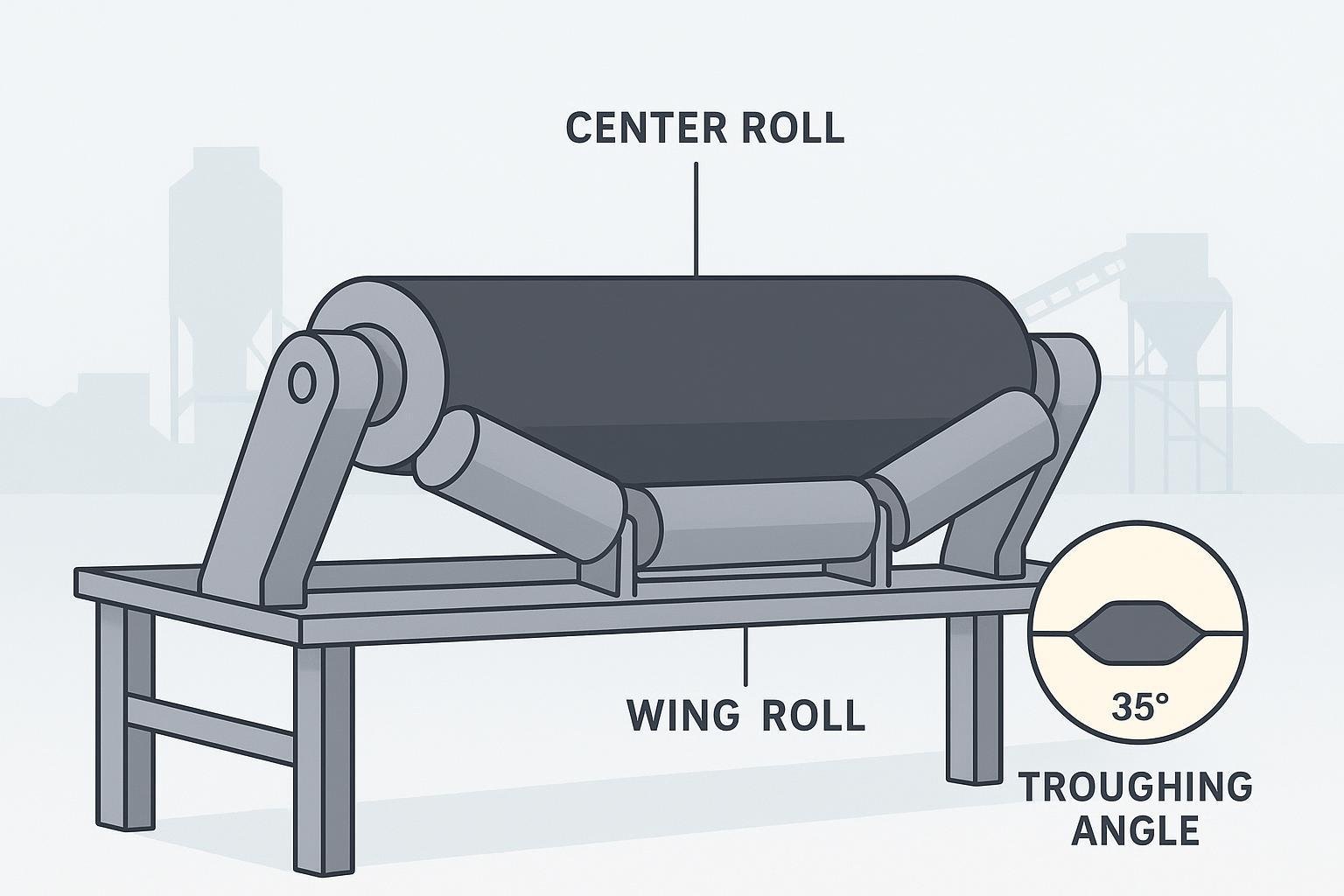
A troughing idler is a set of rollers on the carrying side of a belt conveyor that forms the belt into a U-shape, increasing cross-sectional capacity and supporting the load. Martin Engineering describes these fundamentals in their components overview. In simple terms: the center roll is the horizontal middle roller that supports the belt center; the wing rolls are the two inclined outer rollers that create the trough; the troughing angle is the inclination of each wing roll to the horizontal—North American practice commonly uses 20°, 35°, or 45°. The carry side is the loaded, upper run of the conveyor; the return side is the empty, lower run.
Idler types at a glance
| Idler type | What it looks like | Where it’s used (beginner cues) |
|---|---|---|
| Three-roll troughing | One center roll + two wing rolls | Most common on the carry side; general-purpose materials |
| Five-roll troughing | Center roll + multiple smaller wing/transition rolls | Wider belts or very heavy loads; smoother support profile |
| Two-roll / V-return | Two rolls forming a shallow V on the return | Empty return side to help tracking and reduce belt flap |
| Impact idlers | Rolls with rubber discs or cushioning | Under loading zones to absorb impact and reduce sag |
| Training/self-aligning | Pivoting or steering idler frames | Where mistracking occurs; not too close to pulleys |
For visuals and specifications, see manufacturer catalogs such as PPI’s Idler Catalog and the Martin Sprocket conveyor pulleys & idlers catalog.
Common troughing angles and where they fit
Deeper troughs increase capacity but demand careful transitions and sealing design. North American systems commonly use 20°, 35°, and 45°. A 20° set gives a conservative profile with more free edge for sealing—useful in loading/transfer areas and for materials that don’t need deep troughing. A 35° set is a widely used general-purpose angle balancing capacity and sealing space. A 45° set offers higher capacity for free-flowing materials but requires longer transition distances and close attention to sealing and loading alignment. For context and visuals, authoritative knowledge hubs and catalogs from Martin Engineering and Martin Sprocket cover these standard angle options.
Spacing and sag—beginner principles
Idler spacing determines how much the belt sags between rollers. Excessive sag can shift the load, spill material, and accelerate wear; spacing that’s too tight raises cost and power usage. As a simple rule of thumb for beginners: keep carrying-side spacing tighter because the belt is loaded and must hold a stable trough profile; reduce spacing in the loading zone and consider impact idlers or impact beds to absorb energy and limit sag; return idlers can be further apart because the belt is empty. Final spacing depends on belt width, load, belt carcass stiffness, speed, and roll diameter—confirm exact values with vendor tables and standards.
Transition distance—why it matters
Transition distance is the length over which the belt changes from flat at the pulley to the full trough. If that transition is too short, the belt edges carry too much tension, splices are overstressed, and spillage and tracking issues follow. Use staged angles (transition idlers) to take the belt from flat to full trough progressively, and load the belt only after it reaches the design trough angle to avoid trapping and spillage at the skirtboard. Plan longer transitions for stiffer belts and steeper troughs.
Where to use impact and training idlers
Impact idlers go under loading zones to absorb impact energy and minimize sag. Match their trough angle to the adjacent carrying idlers so the belt profile stays continuous. Training (self-aligning) idlers should be placed where mistracking develops, not too close to pulleys, and their troughing angle should match the carry idlers. First verify the structure and pulleys are square; training devices should supplement, not substitute, proper alignment.
Practical example: choosing a basic setup
Disclosure: BisonConvey is our product.
Scenario: A 36-inch belt moving crushed stone at moderate speed. A three-roll troughing idler at 35° is a common starting point for general-duty materials. Begin with closer carrying-side spacing to control sag under load; tighten spacing further in the loading zone and use impact idlers or an impact bed under the chute. Arrange transition idlers so the belt reaches the full trough before it’s loaded. Final angles, spacing, and transitions must be confirmed with vendor design tables based on belt width/strength, carcass stiffness, material load, speed, and roll diameter.
Inspection and safety essentials
Before any inspection or maintenance, control hazardous energy and protect against pinch points. Follow lockout/tagout (LOTO) procedures per OSHA 29 CFR 1910.147: apply personal locks/tags and verify isolation before work. Ensure machine guards meet OSHA 29 CFR 1910.212, guarding nip points at rolls and the belt. Use proper access platforms and site-approved PPE, keep clear of rotating rolls, clean buildup before restart, reinstall guards, and test-run per site procedures.
Troubleshooting cues
Spillage along the carry side often points to insufficient troughing angle for the material, excessive sag from wide spacing or seized rolls, loading before full trough, or inadequate skirt sealing. Belt edge wear or cupping may result from short transition distances, misaligned idlers, or uneven loading. Mistracking can stem from structure or pulleys out of square, material buildup on rolls, off-center loading, or missing/dirty return idlers—add training idlers only after verifying alignment. Noise or heat at rolls usually signals seized or contaminated bearings or misaligned frames causing edge contact.
Quick FAQs for beginners
- What’s the difference between carry and return idlers? Carry idlers support the loaded upper run and shape the trough; return idlers support the empty lower run, often in flat or V-return configurations.
- Do deeper trough angles always track better? Not necessarily. Deeper troughs increase capacity but require longer transitions and careful sealing; tracking depends on alignment, loading, and maintenance.
- Where should training idlers go? Place them where mistracking develops, away from pulleys, and only after verifying structure/pulley alignment.
- How do I pick spacing? Start with conservative carry-side spacing, tighten in loading zones, and confirm exact spacings from vendor tables based on width, load, and belt properties.
References
- Martin Engineering Foundations (components, spacing, transitions, training)
- Martin Sprocket Conveyor Pulleys & Idlers Catalog
- PPI Idler Catalog
- OSHA 29 CFR 1910.147 (LOTO) and 1910.212 (Machine Guarding)
Next steps
If you’d like a beginner-friendly idler selection sheet or to discuss angles, spacing, and transitions for a specific conveyor, contact BisonConvey’s engineering support at bisonconvey.com.