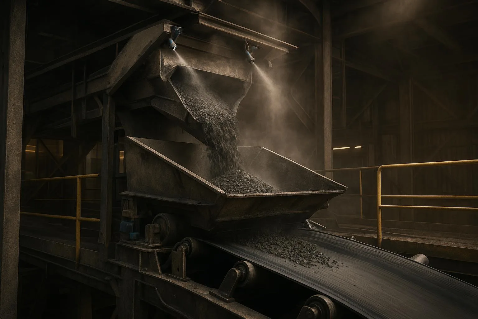
Belt Conveyor Transfer Chute Design Principles
If you run conveyors long enough, the transfer points will tell you how good your design really is. Spillage, dust, belt damage, and idler failures often trace back to how material leaves one belt and enters the next. This guide explains Belt Conveyor Transfer Chute Design Principles from a senior engineer’s perspective and turns them into practical checks you can use on new projects and retrofits.
Transfer chutes are the engineered passages that guide bulk solids from one conveyor (or feeder) to another. The goal is simple to say and hard to achieve: control the stream, match its speed and direction to the receiving belt, absorb impact without punishing components, and keep air and fines contained so your operation stays clean and safe.
Key takeaways
-
Prioritize trajectory control and velocity matching to minimize slip, wear, and dust at the loading zone.
-
Select geometry to fit the duty: hood-and-spoon for controlled redirection; rock-box where material-on-material protection is advantageous.
-
Stabilize the receiving belt with adequate impact support, closer idler spacing, and the right transition distance before tightening skirts.
-
Design for dust: stilling volume, tight enclosures, and venting/collection reduce induced air and escape paths.
-
Verify with DEM where stakes are high, and validate with field inspections—then iterate.
Core concepts engineers should align on
Understand your infeed conditions
Before choosing a chute geometry, capture the infeed envelope:
-
Particle size distribution (top size, fines fraction)
-
Bulk density and moisture
-
Angle of repose/surcharge angle (how material sits on a moving belt)
-
Flow rate range and surges
-
Belt speed and trajectory from the upstream conveyor
-
Drop height, feeder type, and any pre-existing deflectors
These parameters govern discharge trajectory and impact energy. They also influence dust generation and build-up risk. CEMA’s Belt Conveyors for Bulk Materials sets the broader conveyor design context and remains the default reference used across industry; see the official listing in the CEMA 7th edition store page for scope confirmation.
According to guidance in Martin Engineering’s Foundations knowledge hub, effective transfer design manages wear, impact, and airflow by keeping the stream under control and providing generous stilling volume in skirtboards; their chapter on conventional transfer chutes and article on wear provide practical principles. See Foundations Conventional Transfer Chute (excerpt) and Managing Wear at Transfer Chutes.
Trajectory control and velocity matching
Aim to load at—or close to—the receiving belt’s direction and speed. When the incoming stream’s velocity vector is far from the belt’s, the relative slip grinds fines, accelerates cover wear, and launches dust. In plain terms: try to “lay” the stream onto the belt rather than “smack” it into the trough.
Conceptual check:
-
Compute the upstream discharge speed from belt speed and trajectory equations or a simple calculator. Then compare to the receiving belt speed. Reducing the delta reduces impact energy and dust.
-
If you need a quick speed reference, use your internal belt speed calculations. For a handy online option, see Belt Speed Calculator in the BisonConvey engineering tools.
Impact energy management in the load zone
Even with velocity matching, you need to spread and cushion impact:
-
Use impact beds or impact idlers under the first meters of the chute to limit belt sag and bounce.
-
Begin with a slightly shallower trough angle in the impact zone, then transition to full trough over sufficient distance to control edge tension rise (per CEMA/DIN/ISO methods; Helix DeltaT’s help pages summarize common approaches to transitions and vertical curves consistent with those methods). See Helix DeltaT Vertical Curves and Transitions overview.
-
Distribute loading gradually across the transition to avoid sudden lateral forces and mistracking.
A simplified impact energy concept is E ∝ m·Δv²/2 + m·g·h. While you won’t size a cradle solely from this, it reminds us that both relative velocity and drop height matter. Reduce either, and life gets easier for everything downstream.
Receiving belt interface and transition distance
Stable sealing starts with stable support. In practice:
-
Tighten idler spacing in the loading zone (often half or one-third of normal).
-
Use slider bars or impact cradles to create a flat, controlled seal line.
-
Start at ~20° trough in the impact zone, then increase to 35° or 45° as design requires. Verify transition distance to keep edge tension within belt maker limits. Helix DeltaT’s vertical curve/transition overviews align with CEMA/DIN traditions and can help sanity-check edge tension trends.
Dust and airflow basics
Dust is as much an airflow problem as a material problem. Foundations guidance emphasizes:
-
Minimize free-fall and large openings that pull in air.
-
Provide a stilling plenum inside skirtboards to slow air and allow fines to settle.
-
Use curtains and seals to limit induced flow paths.
-
Where needed, connect to a dust collector and maintain slight negative pressure at the enclosure. For exhaust-system design concepts relevant to collectors and ducting, see NFPA 91 committee report materials on exhaust systems and Foundations airflow control guidance.
For worker exposure and confined flows, OSHA ventilation pages provide baseline expectations for engineering controls and work practices. See OSHA 1910.94 Ventilation.
Choosing the geometry: hood-and-spoon vs rock-box
At a high level, you’re choosing between controlled redirection and material-on-material buffering. Both can work well when properly engineered. DEM and field experience should guide the final pick.
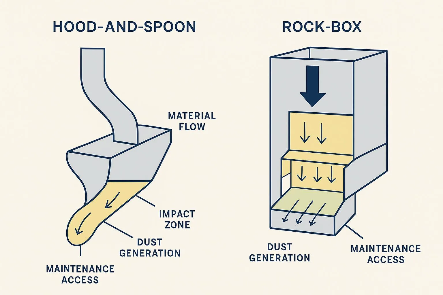
Quick comparison
Notes and sources: Generalized practices summarized from Martin Engineering’s guidance on managing wear and airflow in conventional chutes and public technical papers that discuss engineered curved chutes and rock boxes in transfer design, such as BELTCON literature and Fritella’s design notes.
Selection heuristics without over-claiming
-
Prioritize hood-and-spoon when the top goals are controlled trajectory, reduced material degradation, and dust minimization.
-
Favor rock-box where abrasion is extreme and you want the stream to impact onto a self-renewing material bed. Guard against fines build-up by specifying low-friction liners and generous wall angles.
-
For mixed streams or seasonal moisture swings, plan for inspection access and clean-outs regardless of geometry.
Components and materials that make transfers work
Wear liner strategy (what to use where)
Match liner to impact and abrasion. Keep modules replaceable and accessible.
This summary reflects common vendor-neutral practice notes visible across reputable sources describing chute liners and wear strategies.
Skirt sealing systems for conveyor transfer points
Stable sealing starts with support and correct geometry. Practical best practices emphasized by Foundations and product handbooks include:
-
Keep a free belt edge (often around 115 mm/4.5 in) for sealing and tracking. See “Ten common mistakes” guidance for context on belt edges and support.
-
Support the belt continuously under the seal line with impact beds or slider bars to prevent gaps; Clean belt conveyor design gives an accessible overview.
-
Use external wear liners (outside the skirtboard) to create a step and protect the seal; they’re easier to inspect and replace.
-
Apply light, uniform sealing force via quality clamps; over-tightening accelerates wear. Flexco handbooks provide practical clamp/seal notes, e.g., Flexco Belt Conveyor Products Guide (2024).
-
Set skirt length to cover the settling zone so fines stop moving before the seal ends.
Impact beds, cradles, and rolls
-
Place impact elements beneath the first contact zone to prevent belt puncture and idler damage.
-
After the impact section, use slider/cradle elements to stabilize the belt through the skirted zone.
-
Verify spacing, transition distance, and load distribution with your conveyor calculations or trusted software. See Helix DeltaT transitions overview for principles consistent with CEMA/DIN/ISO.
Dust and enclosure controls: conveyor chute dust control best practices
-
Increase enclosure volume in the skirtboard to slow air and let fines settle.
-
Minimize openings and gaps; use curtains and barrier seals to manage inlet air.
-
Vent to a dust collector sized for the air volume and material; maintain negative pressure at the enclosure per NFPA 91 concepts.
-
Where appropriate, use fog or water sprays positioned to treat airborne dust inside the enclosure without over-wetting material. See Foundations on fog suppression and water suppression.
DEM modeling for transfer chute design and field validation
When the transfer is high-tonnage, abrasive, sticky, or space-constrained, DEM can de-risk the design and reduce iterations in steel. What does “good” look like?
When to use DEM
-
Multiple operating points (start-up, normal, surge) with different flow regimes
-
High velocities/abrasion where wear hotspots need prediction
-
Sticky or cohesive fines prone to hang-ups
-
Tight envelopes or unusual geometries needing evidence before fabrication
Industry overviews from Conveyor Dynamics (chute design) and Jenike & Johanson (DEM services) explain how DEM helps visualize and tune the material stream, predict impacts, and locate dead zones.
Calibration and interpretation
-
Characterize bulk density, particle size/shape, dynamic/static wall friction, angle of repose, and cohesion (if relevant) in the lab.
-
Calibrate until simple test behaviors (e.g., pile angle, chute slide tests) match DEM outputs.
-
Read DEM plots for velocity fields, streamlines, residence time, and impact energy densities; use them to shape liners, adjust hood curvature, or change exit angles.
Limits: DEM often simplifies particle shapes and may not fully capture wet cohesion without careful parameterization. Treat results as decision support, validated by inspection and measurement.
Worked example 1: velocity match and impact concept
Suppose an upstream belt runs at 4.0 m/s and the receiving belt at 3.2 m/s. If the chute can redirect and slightly retard the stream so exit velocity aligns to ~3.2–3.4 m/s in belt direction, relative slip and impact energy drop sharply. Even this coarse tuning reduces cover wear and dust seen at commissioning.
- Need quick checks on belt speeds or capacity during concept design? See BisonConvey Belt Speed Calculator and BisonConvey Belt Capacity Calculator.
Worked example 2: transition and edge-tension sanity check
You plan to move from a 20° trough in the impact area to 35° over a short distance. Edge tension rises if the transition is too abrupt. Use your design package or a method consistent with CEMA/DIN/ISO approaches; Helix’s vertical curve and transition help describes these checks at a principles level. If your calculation flags high edge stress, lengthen the transition or modify idler angles to protect the belt edges and keep skirt seals stable. For belt mechanics context, a quick estimate of tensions is available via the BisonConvey Belt Tension Calculator.
Selection and implementation checklist
Use this condensed checklist during design and commissioning. Think of it as a pragmatic gate review.
-
Geometry
-
Decide hood-and-spoon vs. rock-box based on material duty, dust tolerance, and maintenance preference.
-
Provide adequate cross-section and wall angles to prevent dead pockets and build-up.
-
-
Trajectory and speed
-
Align exit direction with receiving belt; reduce free-fall height.
-
Confirm belt speeds and capacity against expected tonnage. For quick references, use the BisonConvey engineering tools hub, including the Belt Speed Calculator and Belt Capacity Calculator.
-
-
Receiving belt support
-
Closer idler spacing in load zone; impact cradle first, then slider/stabilizer bars.
-
Start with ~20° trough in impact, transition to design trough with verified distance; consult tension/edge stress tools as needed (e.g., Belt Tension Calculator).
-
-
Sealing and dust
-
External wear liners set the step; maintain free belt edge and uniform, light seal pressure.
-
Provide stilling volume, curtains, and controlled air inlets; vent to a collector if necessary and maintain slight negative pressure.
-
-
Access and maintainability
-
Add inspection doors sized for liner modules and cleaning tools.
-
Design for quick-change liners and quick-release skirt clamps.
-
-
Safety and compliance
-
Plan lockout/tagout and confined-space procedures for any internal work. See OSHA LOTO 1910.147 and OSHA confined spaces overview.
-
For combustible dusts, ensure your ventilation and collection follow concepts in NFPA 91; keep negative pressure on the enclosure.
-
Troubleshooting matrix: common symptoms and targeted fixes
These patterns align with conventional transfer-chute and load-zone guidance from Foundations conventional chute content and practitioner blogs.
Maintenance and best practices
A reliable transfer is maintained into reliability—not built and forgotten.
-
Inspection cadence
-
Weekly: check skirt lips, clamp torque, and liner step height; look for fresh polish marks and hot spots.
-
Monthly: measure dust leakage around doors and flanges; verify bed and bar wear; inspect idler roll condition and spacing integrity.
-
Quarterly: assess liner wear patterns and replace modules nearing limits; confirm transition geometry and idler angles haven’t drifted.
-
-
Condition monitoring
-
Spot high-friction zones with thermal imaging during steady load.
-
Trend dust emissions visually or with simple particulate readings at fixed points.
-
Log spillage removal tonnage and PM work orders to quantify improvements after changes.
-
-
Change-out planning
-
Standardize liner module sizes and fasteners.
-
Use quick-release skirt clamps and external wear liners to minimize confined-space entries.
-
Size and place access doors for tool swing and safe handholds. See Martin inspection door OI reference for door sizing/placement concepts.
-
-
Safety callouts
-
Treat chutes as permit-required confined spaces when applicable; follow OSHA’s confined space and LOTO requirements before opening or entering.
-
For combustible dusts, ensure your ventilation and collection follow concepts in NFPA 91 exhaust systems guidance; keep negative pressure on the enclosure side facing the process.
-
Next steps and resources
Authoritative sources for further study:
-
CEMA’s Belt Conveyors for Bulk Materials (7th Ed.) — the industry’s foundational text.
-
Helix DeltaT technical help — clear overviews of transitions/assumptions aligned with CEMA/DIN/ISO practices.
-
Martin Engineering Foundations knowledge hub — conventional chutes, airflow management, and wear control.
-
Conveyor Dynamics: Chute Design and Jenike & Johanson: DEM services — DEM primers and practical insights.
Component matching and quick checks:
- Use engineering tools to sanity-check belt speed, capacity, tension, and incline during concept and retrofit work. BisonConvey maintains a tools hub with calculators, including the Belt Speed Calculator, Belt Capacity Calculator, and Belt Tension Calculator.
If you’re aligning a new or retrofitted transfer with existing belts, idlers, and pulleys and need component data or dimensional compatibility, a brief consultation with BisonConvey can help coordinate specifications across the loading zone.
Conclusion
Here’s the deal: great transfer chutes aren’t just metal boxes—they’re flow-control devices that protect your belt, manage air, and keep tons moving where they should. Anchor your designs in the Belt Conveyor Transfer Chute Design Principles we covered—trajectory control, impact management, stable support and sealing, dust-aware enclosures, and verification with DEM when warranted. Validate in the field, maintain the details, and your loading zones will run cleaner, safer, and longer.