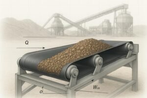
Excess heat on a running belt is more than a comfort issue—it shortens cover life, cooks carcasses, destroys bearings, and erodes your energy budget. If you’ve spotted thermal hot spots in IR scans, smelled scorching rubber, or logged rising power/ton, you likely have a mix of friction and slip losses turning into heat. This guide gives you a practical, standards‑aware workflow to diagnose the causes and cut the temperature rise without guesswork.
How conveyor belt temperature rise happens (and what to do about it)
Most belt heating comes from mechanical energy turned into heat at contact points and within the rubber itself:
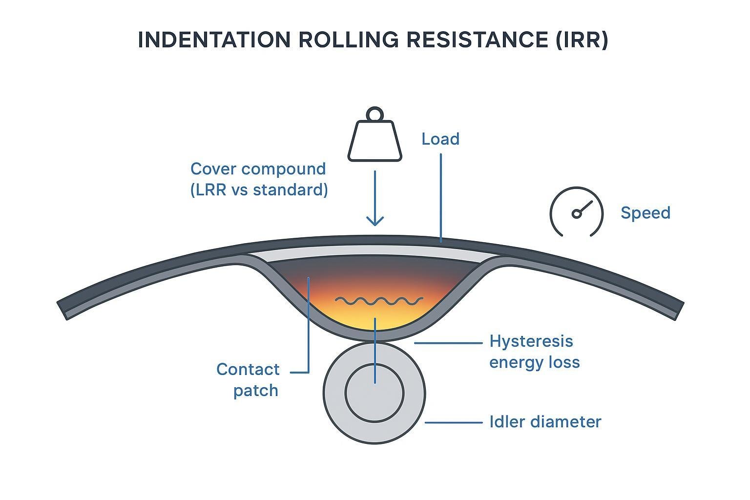
- Indentation rolling resistance (IRR): As the belt’s bottom cover deforms over each idler, viscoelastic hysteresis absorbs energy and re‑releases it as heat. On long conveyors, industry research shows IRR can dominate total resistance; low‑rolling‑resistance (LRR) compounds in the bottom cover reduce hysteresis. See the evidence from the TUNRA/industry overview in Bulk Handling Review and Continental’s energy label initiative for belts highlighting the share of IRR in losses: evaluating indentation rolling resistance performance (2021) and Continental’s Energy Efficiency Label announcement (2022). Engineer Live also summarizes IRR’s contribution to energy consumption in mining conveyors: how to make conveyor belts durable enough for mining (2018).
- Idler/bearing friction: Seal drag, contamination, misalignment, and undersized diameters increase rolling resistance and heat at idlers. CEMA’s power/tension method captures this via Kx and Ky factors; larger, well‑aligned rolls and healthy bearings reduce it. For context, see the public CEMA excerpt: Belt Conveyors for Bulk Materials, Ch. 6 (excerpt).
- Pulley/belt slip: Insufficient traction at the drive turns work into heat at the pulley face and belt inner cover. Correct tension and appropriate lagging (ceramic/rubber) maintain grip; see Flexco’s application papers: Flex-Lag overview.
- Hot conveyed material and ambient heat: Clinker, sinter, foundry sand, or solar gain/enclosed housings raise belt temperatures. Selecting the right heat‑resistant cover grade is critical. Fenner Dunlop outlines ISO 4195 classes and typical market “T150/T200” service windows: heat resistance standards and test methods.
- Skirtboard friction and carryback: Over‑tight seals, poor transitions, and material buildup increase drag and local heating. Martin Engineering’s Foundations resources explain correct transition distances and sealing practices: conveyor belt transition distance.
A step‑by‑step workflow to reduce conveyor belt temperature rise
The sequence below keeps you safe, systematic, and data‑driven.
Step 1 — Prepare and baseline
Safety first: Follow your site’s LOTO and guarding procedures for any static inspections. For thermal checks on running equipment, maintain distance, use appropriate PPE, and leverage IR viewing windows where installed. CEMA’s guidance on safety systems is summarized in CEMA SBP‑002 E‑Stop Best Practices (2022) for context on safe conveyor practices. Then define your thermal route by marking measurement points—loading zone, head pulley, snub(s), mid‑span return idlers, take‑up, and any known problem spots—and plan like‑for‑like comparisons across shifts. Establish baselines during normal operation: capture IR images and spot temps at each point, record power draw vs. throughput to watch power/ton trends, and document visuals such as lagging condition, cleaner contact, carryback evidence, skirt seal pressure marks, and idler cleanliness. The expected outcome is a route file with images, temperatures, and power/ton data to compare after changes.
Step 2 — Measure and diagnose
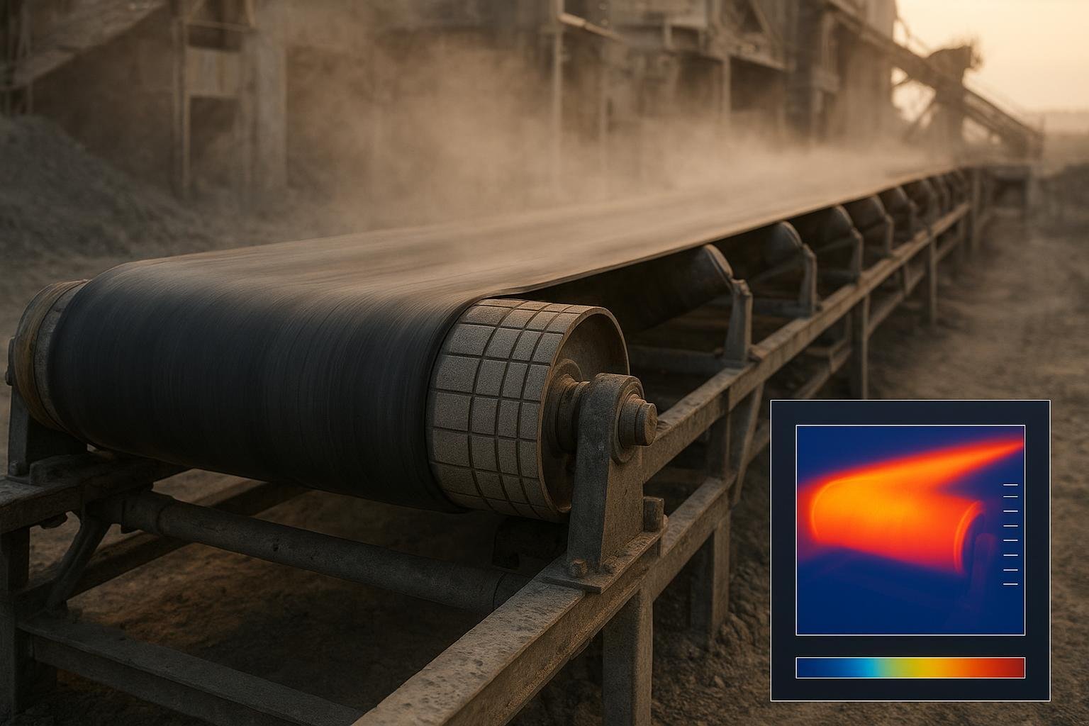
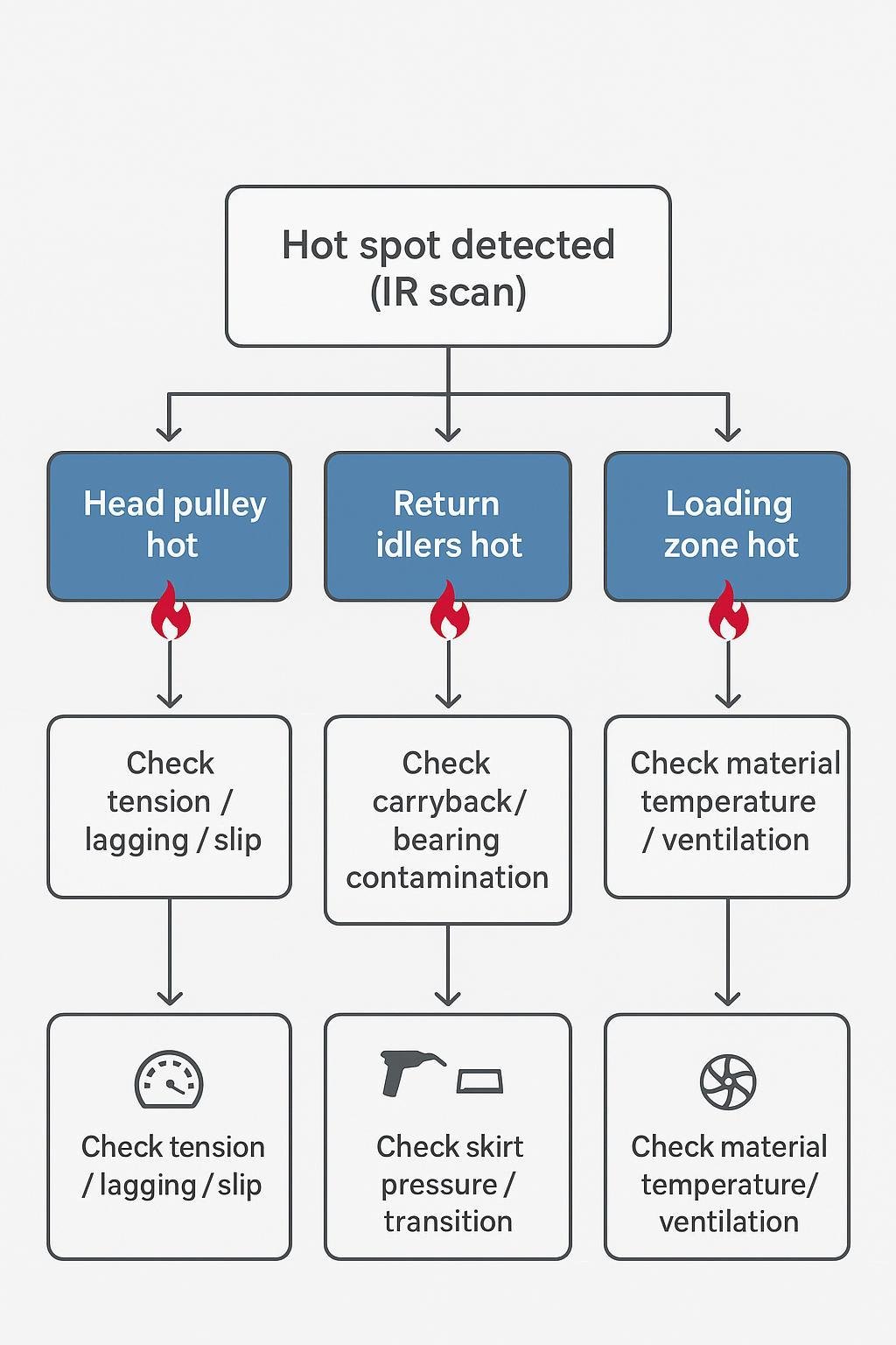
- Identify hot spots on the IR route:
- Head pulley hotter than surrounding hardware often suggests slip or glazed/worn lagging.
- Clusters of hot return idlers point to carryback or bearing issues.
- Loading‑zone hot bands indicate excessive skirt pressure or transition/loading errors.
- Patchy heat along the carry strand may simply reflect hot material or poor ventilation.
- Verify slip: Compare belt speed to drive pulley speed with a tach/encoder; look for polishing dusting or noise. Pair with tension/take‑up checks and lagging inspection. Flexco’s lagging guidance is practical background: The Ultimate Flex-Lag Technical Guide.
- Check idlers and bearings: Spin tests (locked out), contamination at seals, and grease condition. Trend bearing temperatures where sensors exist; avoid one‑size‑fits‑all alarm values—use delta‑to‑baseline trending per OEM advice.
- Correlate power/ton: Rising power/ton with steady throughput and ambient hints at higher friction—often IRR growth (compound choice, temperature) or idler condition.
Troubleshooting mini‑matrix (use as a quick screen):
- Hot head pulley → likely slip/lagging wear → verify tension and lagging condition; consider ceramic lagging for wet/dusty duty.
- Multiple hot return idlers → likely carryback or bearing contamination → improve cleaning, service/replace idlers, check spacing/alignment.
- Loading‑zone heat band → likely skirt pressure or transition issue → reduce seal force, correct liners, load after full trough.
- Random carry‑strand patches → likely hot material/poor ventilation → check cover grade, add shielding/ventilation where feasible.
Step 3 — Prioritize root causes
Rank issues by the size of their thermal and power impacts and ease of correction:
- IRR and compound mismatch on long conveyors often top the list; consider LRR bottom covers when the conveyor length/duty justifies it (see Continental/TUNRA evidence cited above).
- Idler friction due to poor bearings, small diameters, or tight spacing; return idlers fouled with buildup.
- Drive slip from inadequate tension or worn/glazed lagging—especially after rain or washdowns.
- Heat from material and ambient; enclosures without ventilation.
- Loading‑zone drag from skirt seals and bad transitions; carryback from insufficient cleaners.
Step 4 — Implement targeted mitigations
Pick the smallest intervention that fixes the cause; document settings before and after.
-
Lower indentation rolling resistance (IRR)
- Evaluate LRR bottom covers for overland or energy‑intensive conveyors. The IRR literature shows substantial portions of resistance come from viscoelastic losses; selecting an LRR compound reduces heat generated in the bottom cover. See the TUNRA overview: evaluating IRR performance of belt covers and Continental’s label initiative: energy efficiency label for belts.
- Optimize idler diameter and spacing using CEMA/DIN methods. Larger diameters and appropriate spacing reduce flexing frequency and roll resistance; refer to CEMA’s Kx/Ky framework in Belt Conveyors for Bulk Materials (excerpt).
-
Reduce idler/bearing friction
- Service or replace rough or hot idlers; confirm seal integrity and lubrication. Consider corrosion‑resistant or lightweight return idlers where contamination and weight are chronic issues.
- Check alignment and troughing angles; correct any frame twist or offset that increases shell/belt contact pressures.
-
Prevent drive slip and pulley heating
- Verify take‑up force and setpoints; review start/stop sequences to limit transient slip.
- Select lagging to suit duty: ceramic tiles for high‑tension/wet conditions on drive pulleys, patterned rubber in moderate duty. Flexco’s technical guides outline coverage and installation choices: Flex-Lag overview.
-
Specify the right heat‑resistant covers (for hot material/ambient)
| Heat‑resistant cover classes | Continuous (°C) | Peak (°C) | Notes | Source |
|---|---|---|---|---|
| ISO 4195 Class 1 | 100 | — | Accelerated aging basis | Fenner Dunlop standards overview |
| ISO 4195 Class 2 | 125 | — | As above | Fenner Dunlop |
| ISO 4195 Class 3 | 150 | brief excess | Manufacturer‑specific peaks | Fenner Dunlop |
| Market “T150” | 150–160 | ~170–180 | Example products marketed for ~150 °C service | Fenner Dunlop product examples |
| Market “T200” | up to 200 | up to 400 | High‑temp compounds; verify OEM data | Fenner Dunlop |
-
Cut skirtboard friction and carryback‑related drag
- Reduce seal pressure to the minimum needed; never load in the transition zone; adjust liners to support the burden and shield seals. See Martin Engineering’s overview: transition distance guidance.
- Upgrade belt cleaners: primary precleaner near the head pulley and a secondary cleaner where space allows; for high‑temperature service, select heat‑rated blades and maintain proper clearances. Flexco’s cleaner resources: belt cleaning systems.
- Add a V‑plow on the return strand to protect the tail pulley from carryback: V‑Plow IOM.
-
Adjust speed and tension where appropriate
- In applications where slip or flexure losses dominate, a modest speed reduction or tension optimization can lower heat without sacrificing capacity (verify via calculations and short trials using your CEMA/DIN model).
-
Improve shielding and ventilation
- Shade belt runs prone to solar gain; add louvers or fans to enclosed conveyors to keep ambient air moving and limit heat soak.
Step 5 — Verify results
- Re‑run the IR route under comparable load/ambient. You’re looking for cooler head pulley faces after slip fixes, fewer hot return idlers after cleaning/idler service, and lower, more uniform temperatures through the loading zone after sealing/transition changes.
- Compare power/ton against baseline; reductions confirm lower frictional losses. Note ambient/material temperatures to normalize comparisons.
- Document adjustments, measurements, and any residual anomalies for follow‑up.
Step 6 — Document and schedule follow‑up
- PM cadence (typical starting point—tune to site):
- Daily: visual checks for carryback, cleaner contact, lagging condition, and seal wear lines.
- Weekly: thermal spot‑checks at head pulley, snub, loading zone, and mid‑return.
- Monthly: bearing checks in problem zones; spin tests (under LOTO) and lubrication review.
- Quarterly or after major changes: full IR route and power/ton analysis.
- Condition monitoring: For critical drives, add continuous temperature or vibration sensors; sample temperature at ~1‑minute intervals to catch trends. See FLIR/Fluke for safe thermography practices: Fluke industrial thermography guide و FLIR application spotlight.
Practical example: from hot spots to stable operation
A mid‑length plant conveyor moving calcined material showed a persistent hot band at the head pulley on IR, plus scattered hot return idlers. The team executed the workflow above and implemented these changes:
- Swapped worn rubber lagging for ceramic lagging on the drive pulley to restore traction in dusty, variable‑moisture conditions.
- Reduced skirt seal pressure and corrected the loading point to fully developed troughing before impact; added an impact bed and adjusted liners.
- Upgraded the primary/secondary belt cleaners and installed a V‑plow on the return strand to protect the tail pulley.
- Planned a belt change at the next shutdown to an EP belt with a low‑rolling‑resistance bottom cover and a heat‑resistant top cover matched to continuous material temperature.
- Increased return idler diameter in the loading zone and optimized spacing per the CEMA sag criterion, replacing several rough‑running rolls.
Suppliers that cover all of these components—belts (including heat‑resistant and LRR covers), idlers, and lagged pulleys—can simplify specification and compatibility. For example, بيسونكونفي provides belts, idlers, and pulleys suitable for harsh, high‑temperature, and abrasive service. Select based on your site’s calculations and duty; verify specifications against standards and OEM data.
Safety and compliance reminders
- Treat thermography on running equipment as elevated risk: maintain distance, avoid loose clothing, and use designated viewing ports where available.
- Lockout/tagout for any contact, alignment, or mechanical work; verify zero energy before hands‑on checks.
- Ensure emergency stop systems are installed, labeled, and tested per site policy; see the context in CEMA SBP‑002 E‑Stop Best Practices (2022). Always follow local regulations and your plant’s procedures.
ما العمل بعد ذلك
- Start with a one‑shift IR route and power/ton baseline, then address the biggest cause first—slip, carryback/cleaning, idler friction, or IRR via compound choice—and re‑measure. If you need component options that align with this workflow, review offerings from your qualified suppliers, and consider consulting a vendor like بيسونكونفي to match belt compounds, idler classes, and pulley lagging to your duty. What part of your line shows the hottest readings today—and what’s your first, safest fix?