Reducing conveyor belt wear isn’t about one silver-bullet component. It’s a system problem shaped by loading geometry, material behavior, belt selection, cleaning efficiency, tracking/tension, and the environment. Get those right and you extend belt life, stabilize uptime, and cut housekeeping.
Before we begin, a safety reminder: always follow lockout/tagout procedures and site-specific permits before any inspection or adjustment work.
Here’s a practical, standards-aware workflow you can apply on any bulk-material conveyor to reduce conveyor belt wear and prove the gains with simple KPIs.
Diagnose the wear before you fix it
Not all wear is the same, and different patterns point to different root causes:
- Top-cover abrasion concentrated in the loading zone usually signals high-impact, misaligned flow, or excessive skirting pressure.
- Gouging at first contact suggests excessive drop height or sharp lumps without energy control.
- Edge grooves and frayed carcass fibers point to mistracking, loading in transition, or uneven support under skirts.
- Splice scuffing near the head pulley often ties back to cleaner setup or lagging/glazing and slip.
Quick field checks to establish a baseline:
- Mark a 100 × 100 mm chalk or paint grid at several fixed stations in and after the load zone, then spot-check top-cover loss monthly with a depth gauge. Track mm lost vs. tonnage handled.
- Quantify carryback by collecting and weighing adhered fines per square meter of belt after discharge. Use this to calculate housekeeping tonnage/day and set a target.
About lab tests vs. field results:
- Abrasion resistance is commonly characterized by the ISO 4649/DIN 53516 drum test; lower mm³ volume loss indicates better abrasion resistance. Industry summaries explain both the method and its limits moving from lab to reality. See Dunlop’s technical overview in Abrasion Standards and Test Methods (2019–2024) for context and typical ranges discussed for selection guidance: Dunlop’s abrasion standards and test methods.
- For the broader classification landscape (EN ISO 14890 H/D/L vs. DIN 22102 X/W/Y) and how industry maps them in practice, DryCargoMag’s overview provides a concise survey: DryCargoMag on conveyor belt quality standards and testing (2019).
- In the U.S., RMA/ARPM grades and the PICO abrasion test are referenced; there’s no direct conversion to DIN/ISO mm³, so treat them as separate indicators. A clear explanation is in Pooley’s technical note: Pooley’s guide to abrasion resistance and the PICO test (2021).
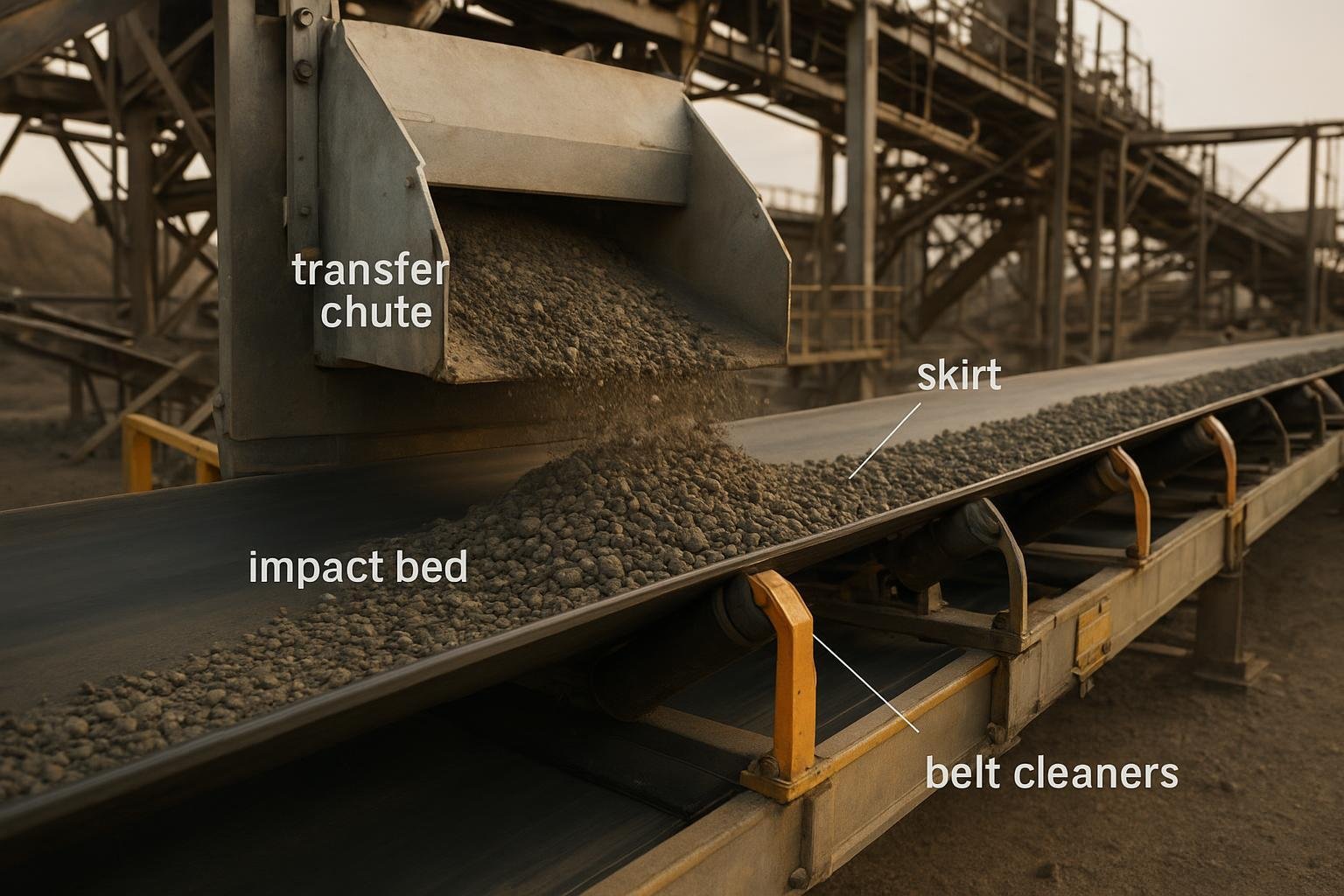
Engineer the transfer and loading zone to reduce conveyor belt wear
Most premature wear starts where material meets the belt. Fixing the geometry and support here often yields the largest gains.
Principles to implement:
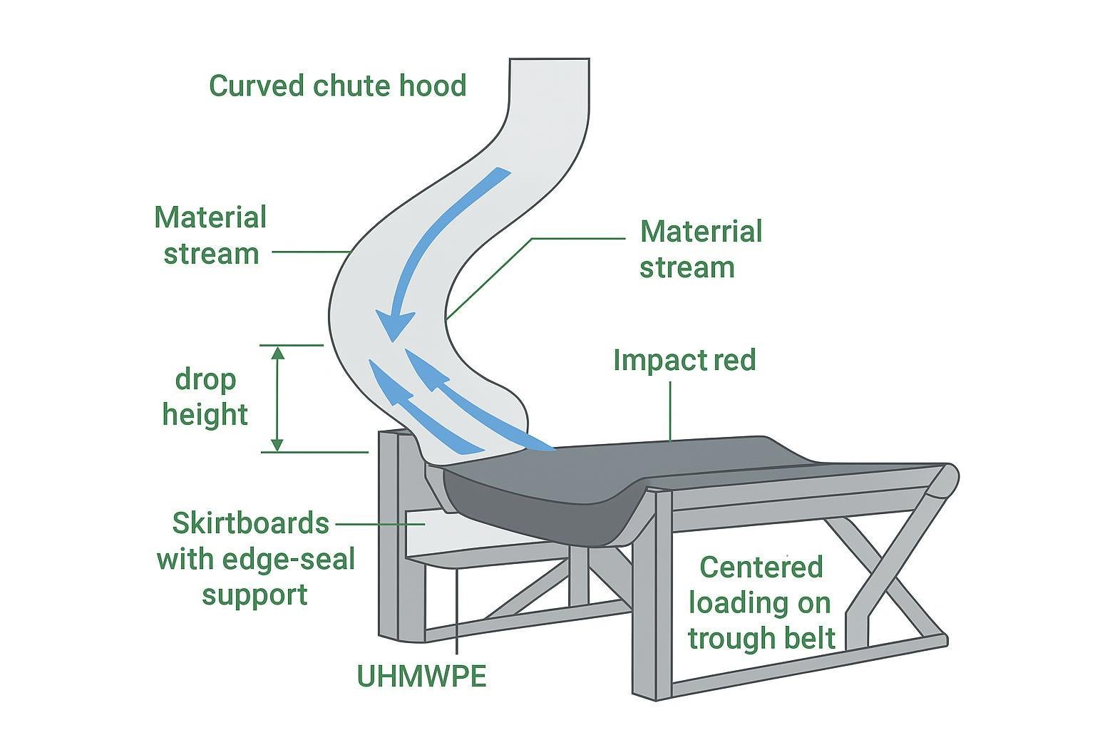
- Center loading and speed-matching: Accelerate the material stream in the belt’s direction to reduce impact and scouring. Curved or spoon chutes make this feasible where space allows.
- Control drop height: Keep free-fall as low as practical; when unavoidable, manage velocity with hood-and-spoon chutes or energy-dissipating features.
- Give the flow room: Valley angles of at least 60°, and often 75°, help prevent buildup that grinds on the cover.
- No loading in transition: Load only after the belt reaches full trough on properly spaced idlers.
- Provide continuous support under skirts: Use impact beds/cradles and edge-seal support so the belt line is stable and the seal pressure stays even.
Authoritative guidance and design detail are available in these resources:
- Martin Engineering’s Foundations knowledge base discusses chute geometry, valley angles, and soft loading concepts with workable rules of thumb: Martin Engineering’s transfer chute design considerations.
- ASGCO’s engineering guide shows curved/spoon chute concepts, impact protection, and speed-matching principles suitable for retrofits: ASGCO Transfer Point Design and Fabrication (PDF).
Illustration: a transfer-point cross-section that aligns the stream, stabilizes the belt line, and protects wear zones.
Component choices that pay off here:
- Impact beds or cradles sized for drop energy to limit sag and seal “breathing.”
- Edge-seal support cradles that keep the belt edge flat and reduce groove formation.
- Low-friction liners (UHMWPE or ceramic) on high-velocity contact surfaces to reduce abrasive scouring.
- Correct skirt pressure: firm enough to seal, not so high that it acts like a brake. Aim for even contact across the full length.
Select the right cover grade and critical components
Choose the belt to match the duty—not just tensile rating, but covers and carcass constructions that resist the dominant wear modes.
- Cover classes: In practice, EN ISO 14890 classes (H/D/L) and DIN 22102 classes (X/W/Y) are used to describe abrasion resistance, with values informed by ISO 4649/DIN 53516 testing. Treat published mm³ figures as indicative ranges from manufacturers rather than normative thresholds. For industry context and typical mappings, see the DryCargoMag standards overview and Dunlop’s technical note: DryCargoMag on testing and classes و Dunlop’s abrasion standards and test methods.
- U.S. context: RMA/ARPM grades and the PICO test reflect different test philosophy (cut/gouge). There’s no reliable direct equivalence to DIN/ISO abrasion numbers. See Pooley’s PICO vs. DIN/ISO explanation for selection caveats.
- Lagging: Use ceramic lagging on high-speed, wet, or slip-prone drives to curb slip-induced heat and glazing. Rubber lagging is typically gentler on covers but may slip sooner; pair with correct tensioning.
- Idlers: In load zones, impact-rated troughing idlers or cradles stabilize the belt. Sealed-for-life rollers reduce seizure and scoring from fines.
- Breaker fabrics/rip-stop: Where tramp metal risk is real, select carcasses with breaker plies or rip-stop features to avoid catastrophic cuts.
- Liners and skirts: UHMWPE or ceramic liners in chutes and skirtboards concentrate wear on replaceable surfaces instead of the belt cover.
Two quick selection prompts you can use during RFQs:
| Duty/material | Cover and component hints |
|---|---|
| Very abrasive, fine ores | Specify abrasion-resistant cover class (e.g., DIN W or EN ISO D as appropriate); consider ceramic lagged drive pulley; ensure full-length impact support and UHMWPE liners. |
| Large, sharp lump with drop | Use tougher top cover with good cut/gouge resistance; fit impact beds sized to energy; adopt spoon chute to align flow and reduce gouging. |
| Wet, clay-rich carryback | Pair abrasion-resistant cover with robust primary + secondary cleaners and a return plow; consider ceramic lagging for grip; verify cleaner compatibility with splice. |
| Oily or fertilized materials | Use oil-resistant cover compound; check cleaner blade material for chemical compatibility; ensure enclosure to limit contamination. |
| Hot clinker or calcined product | Heat-resistant compound per manufacturer range; shield splices and verify maximum continuous/peak temperature capability. |
Clean the belt and control carryback
Carryback is slow-motion abrasion. It embeds under idlers, scores covers, drives roller failure, and multiplies housekeeping. Getting cleaning right is one of the most direct ways to reduce conveyor belt wear.
What “good” looks like:
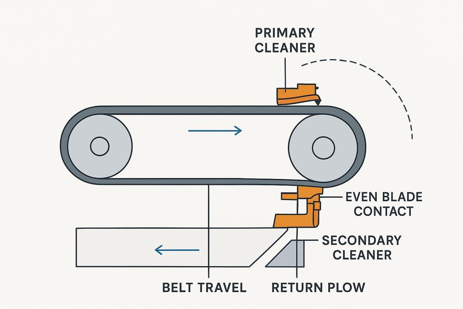
- Primary cleaner at the head pulley set to a low-pressure peeling angle; secondary cleaner just after the head on a taut return strand to remove remaining fines; return plow ahead of the tail pulley to protect splices.
- Even blade contact and correct tension across the full belt width; verify after thermal and load changes.
- Quantify performance. As a practical benchmark, Level II cleaning performance corresponds to roughly 11–100 g/m² of carryback, while ≤100 g/m² is a reasonable general target for many plants. See the methodology and levels discussed in Martin’s overview: Martin Engineering on belt cleaning effectiveness and carryback levels%20Sept,%202021.01.pdf).
Placement and setup at a glance:
Measurement tip you can use this week:
- Carryback to housekeeping tonnage/day ≈ (g/m² × belt width m × belt speed m/s × 3600 × hours/day) ÷ 1,000,000. Use this to justify tensioning improvements or a secondary cleaner upgrade.
Keep it tracked and correctly tensioned
Edge wear and splice fatigue often trace back to transitions and tracking. A few geometry checks curb most of it.
- Transition distances: If manufacturer charts aren’t on hand, use a conservative rule-of-thumb of at least 2.5–3.0× belt width for flat-to-trough transition, and never load before full trough. Martin Engineering’s guides explain the logic and show typical layouts: Martin’s guidance on transition zones.
- Tracking aids: Use training idlers/trackers on both the carry and return runs where persistent drift appears; keep the return run clean to avoid buildup that steers the belt.
- Take-up and tension: Under-tension exaggerates sag and seal breathing; over-tension increases heat and bearing load. Verify take-up travel, recheck after major temperature swings, and measure belt stretch over time.
- Pulley/roller condition: Glazed lagging or frozen rollers slice covers. Add those checks to your monthly walkdown.
Match compounds to the environment
Even perfect geometry can’t save a belt from the wrong compound. Temperature, oils, ozone, and cold can accelerate wear mechanisms if you don’t specify the right cover.
- Heat: For cement clinker or foundry service, select heat-resistant compounds verified for your continuous and peak temperatures. OEMs publish ranges and application notes; for example, Fenner Dunlop Americas outlines sustained temperature capabilities for heat-resistant products and compounds: Fenner Dunlop’s heat-resistant compound pages.
- Oils and solvents: Fertilizers, biomass, and certain chemicals demand oil-resistant covers; double-check cleaner blade compatibility and enclosure designs.
- Ozone/UV and cold: If your belt runs outdoors in freezing climates, specify cold- and ozone-resistant formulations to prevent surface cracking and embrittlement; consult manufacturer data for lower-temperature limits.
Practical example: a loading-zone retrofit that cuts wear
At a quarry receiving belt with chronic top-cover scoring and edge grooves, the team scheduled a 24-hour outage to tackle the transfer point. The retrofit plan focused on stabilizing the belt line and softening the material entry without changing the structure steel.
What they changed:
- Replaced three idler sets beneath the chute with a modular impact bed to provide continuous support under the skirts.
- Installed UHMWPE liners on the chute’s impact surfaces and added a gentle spoon hood to align the stream with belt direction.
- Reduced drop height by 200 mm by adjusting the chute lip and added an edge-seal support cradle to keep seal pressure even.
- Upgraded the drive pulley to ceramic lagging to eliminate wet-weather slip and the glazing that had been heating the cover.
Result after 60 days: measured carryback fell from ~180 g/m² to ~60 g/m², edge-groove growth effectively stopped, and the monthly cover-thickness loss in the first meter after the load zone halved. Similar retrofits can be sourced from multiple suppliers; for belts, idlers, pulleys, and liners, a systems-oriented vendor such as بيسونكونفي can be used to match components to site conditions without relying on any single feature claim.
Verify results and sustain the gains
Tie your fixes to numbers. If the interventions work, you’ll see the deltas in a few weeks.
KPIs worth tracking:
- Carryback level (g/m²) and housekeeping tonnage/day derived from belt width, speed, and run hours.
- Top-cover thickness trend (mm) at fixed stations vs. throughput handled.
- Tracking events per shift and edge condition score (e.g., 0–3 scale for grooves/fray).
- Mean time between belt repairs and unscheduled downtime hours.
- Cleaner blade life and tension drift between checks.
Inspection and maintenance cadence (printable-style reference):
| Interval | What to check | Target/notes | Typical time | Difficulty |
|---|---|---|---|---|
| Daily/shift | Spillage, belt tracking, unusual idler noise; look for hot spots at cleaners | No persistent drift; no visible plumes; no scraping noise | 10–20 min | Beginner |
| Weekly | Cleaner tension and even blade contact; return plow condition | Carryback trending toward ≤100 g/m²; even wear across width | 20–30 min | Intermediate |
| Monthly | Top-cover thickness at marked grids; idler rotation and bearing temp; lagging condition | Thickness loss stabilizing or slowing; no seized rollers | 45–60 min | Intermediate |
| Quarterly | Transition zones, loading in full trough only; chute liners and skirt wear; take-up travel | No loading in transition; stable seal line; adequate take-up | 1.5–3 h | Advanced |
A quick close-the-loop routine:
- Re-measure carryback and cover thickness at your baseline locations.
- Recalculate housekeeping tonnage/day and compare to pre-project values.
- Note any reduction in tracking events and edge-groove progression.
- Decide whether to tighten cleaner tension, extend impact support, or adjust chute lip based on the data.
If the numbers don’t move, revisit assumptions. Are you still loading in transition? Are seals breathing because the belt sags between supports? Are cleaners unevenly tensioned after temperature swings? Small geometry misses can hide in plain sight—fix those first.
Sources and further reading
- Standards landscape and lab tests explained with field cautions: DryCargoMag’s conveyor belt standards overview (2019) و Dunlop’s abrasion standards and test methods.
- U.S. abrasion context and PICO test notes: Pooley’s technical note on abrasion resistance (2021).
- Transfer-point design and soft loading: Martin Engineering Foundations on transfer chute design و ASGCO’s transfer point design guide (PDF).
- Cleaning effectiveness and quantitative carryback levels: Martin Engineering’s belt cleaning effectiveness article (2021)%20Sept,%202021.01.pdf).
- Transition distances and “don’t load in transition” reminders: Martin’s blog on transition zones.
- Heat-resistant compound ranges and application notes: Fenner Dunlop Americas heat-resistant product page.
Closing thought
If you audit just one transfer point this week, you’ll likely find two or three small geometry or support changes that pay back fast. Think of it this way: every kilogram of carryback you keep off the return run is a kilogram that doesn’t sandpaper your belt for hours after discharge. Reduce conveyor belt wear by fixing the flow, supporting the belt, cleaning effectively, and proving it with numbers—then keep the cycle going.